EP1206849B1 - Method for synchronizing base stations in a mobile communication system - Google Patents
Method for synchronizing base stations in a mobile communication system Download PDFInfo
- Publication number
- EP1206849B1 EP1206849B1 EP00951751A EP00951751A EP1206849B1 EP 1206849 B1 EP1206849 B1 EP 1206849B1 EP 00951751 A EP00951751 A EP 00951751A EP 00951751 A EP00951751 A EP 00951751A EP 1206849 B1 EP1206849 B1 EP 1206849B1
- Authority
- EP
- European Patent Office
- Prior art keywords
- base station
- synchronisation
- base stations
- random access
- access channel
- Prior art date
- Legal status (The legal status is an assumption and is not a legal conclusion. Google has not performed a legal analysis and makes no representation as to the accuracy of the status listed.)
- Expired - Lifetime
Links
Images

Classifications
-
- H—ELECTRICITY
- H04—ELECTRIC COMMUNICATION TECHNIQUE
- H04W—WIRELESS COMMUNICATION NETWORKS
- H04W64/00—Locating users or terminals or network equipment for network management purposes, e.g. mobility management
-
- G—PHYSICS
- G01—MEASURING; TESTING
- G01S—RADIO DIRECTION-FINDING; RADIO NAVIGATION; DETERMINING DISTANCE OR VELOCITY BY USE OF RADIO WAVES; LOCATING OR PRESENCE-DETECTING BY USE OF THE REFLECTION OR RERADIATION OF RADIO WAVES; ANALOGOUS ARRANGEMENTS USING OTHER WAVES
- G01S5/00—Position-fixing by co-ordinating two or more direction or position line determinations; Position-fixing by co-ordinating two or more distance determinations
- G01S5/02—Position-fixing by co-ordinating two or more direction or position line determinations; Position-fixing by co-ordinating two or more distance determinations using radio waves
-
- H—ELECTRICITY
- H04—ELECTRIC COMMUNICATION TECHNIQUE
- H04B—TRANSMISSION
- H04B7/00—Radio transmission systems, i.e. using radiation field
- H04B7/24—Radio transmission systems, i.e. using radiation field for communication between two or more posts
- H04B7/26—Radio transmission systems, i.e. using radiation field for communication between two or more posts at least one of which is mobile
- H04B7/2662—Arrangements for Wireless System Synchronisation
- H04B7/2671—Arrangements for Wireless Time-Division Multiple Access [TDMA] System Synchronisation
- H04B7/2678—Time synchronisation
- H04B7/2687—Inter base stations synchronisation
- H04B7/2696—Over the air autonomous synchronisation, e.g. by monitoring network activity
-
- H—ELECTRICITY
- H04—ELECTRIC COMMUNICATION TECHNIQUE
- H04J—MULTIPLEX COMMUNICATION
- H04J3/00—Time-division multiplex systems
- H04J3/02—Details
- H04J3/06—Synchronising arrangements
- H04J3/0635—Clock or time synchronisation in a network
- H04J3/0682—Clock or time synchronisation in a network by delay compensation, e.g. by compensation of propagation delay or variations thereof, by ranging
-
- G—PHYSICS
- G01—MEASURING; TESTING
- G01S—RADIO DIRECTION-FINDING; RADIO NAVIGATION; DETERMINING DISTANCE OR VELOCITY BY USE OF RADIO WAVES; LOCATING OR PRESENCE-DETECTING BY USE OF THE REFLECTION OR RERADIATION OF RADIO WAVES; ANALOGOUS ARRANGEMENTS USING OTHER WAVES
- G01S5/00—Position-fixing by co-ordinating two or more direction or position line determinations; Position-fixing by co-ordinating two or more distance determinations
- G01S5/02—Position-fixing by co-ordinating two or more direction or position line determinations; Position-fixing by co-ordinating two or more distance determinations using radio waves
- G01S5/06—Position of source determined by co-ordinating a plurality of position lines defined by path-difference measurements
Definitions
- the present invention relates to improvements in or relating to mobile telecommunications systems and is more particularly concerned with synchronisation of base stations within a telecommunications system.
- Reliable operation in the UTRA TDD mode requires synchronisation between base stations within a compliant telecommunications system.
- the mode also requires the provision of position information for the mobile stations affiliated to each base station. Synchronisation between base stations is also desirable in order to maximise system capacity.
- the synchronisation of base stations must be achieved at the levels of time slots, frames and multi-frames, where a multi-frame is a repeating cycle of a number of frames.
- GPS global positioning system
- the base stations are synchronised over the backhaul network; the network which enables base stations to switch mobile communications into public telephone networks or the internet.
- this mechanism is implemented according to a packet protocol (for example, internet protocol (IP) or asynchronous transfer mode (ATM)), then synchronisation will only be possible to a coarse accuracy.
- IP internet protocol
- ATM asynchronous transfer mode
- a method of providing synchronisation between a plurality of base stations in a telecommunications system for each base station there is a telecommunications cell within which there is at least one mobile station and for each base station the method comprises the steps of: providing at least one channel for usage in the telecommunications cell; a transmission step, wherein said at least one channel is utilised for transmission of a synchronisation signal, the transmission being from a first base station to those remaining base stations within the telecommunications system which are within transmission range; and a first calculation step, in which a time difference between clock pulses from the first base station and clock pulses transmitted by other base stations within transmission range is calculated.
- the method has the further steps: a reporting step, in which each of the plurality of base stations reports the time differences calculated in the time difference calculation step to a radio network controller; a second calculation step, wherein a synchronising adjustment corresponding to each base station is calculated from the reported time differences; and an adjusting step, wherein each base station is individually sent the corresponding synchronising adjustment and the clock of the base station concerned is adjusted accordingly.
- each of the plurality of base stations can act autonomously on the basis of information received from the available remaining base stations to adjust the clock timing of that base station.
- the channel utilised for transmission of the synchronisation signal is preferably a random access channel (RACH) which is transmitted at a frequency within a band of frequencies that is provided for communications with mobile stations.
- the random access channel advantageously comprises a single time slot per TDMA frame. More preferably, the RACH is allocated to transmissions from mobile stations to initiate communications. Preferably, communications are initiated by requesting a resource unit (time slot and CDMA code combination) for uplink usage.
- the method preferably further comprises a scheduling step in which the utilisation of each RACH time slot for base station synchronisation is allocated according to a schedule.
- the method further comprises a silencing step in which a second channel is used by the base station to silence mobile station communications in the RACH time slots to allow the transmission of synchronisation transmissions to other base stations.
- This second channel is most preferably the broadcast control channel (BCCH).
- the UTRA TDD mode is illustrated.
- Information is transmitted in bursts at a certain combination of frequency, time (within a frame 102), and coding.
- Frames 102 are divided into time slots 104 and each time slot is just long enough for a single burst of information.
- Transmission of information is multiplexed through the use of orthogonal codes (CDMA).
- CDMA orthogonal codes
- the information transmitted within a particular time slot is divided according to these codes: as a result, each burst contains a plurality of independent time slot and code combinations, called resource units 106.
- the UTRA TDD mode uses a scheme called Time Division - Code Division Multiple Access (TD-CDMA).
- TD-CDMA Time Division - Code Division Multiple Access
- This scheme provides for a random access channel (RACH) which is a single time slot 104 per TDMA frame 102.
- RACH random access channel
- the RACH is allocated to transmissions from mobile stations to initiate communications, usually by requesting a resource unit 106 for uplink usage.
- each TDMA frame 200 contains a plurality of time slots 210; fifteen time slots in TDD mode, as shown.
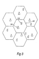
- Figure 3 depicts a typical cellular deployment.
- Each base station 300 has an associated cell 320.
- the range between neighbouring base stations 300 is roughly double the range from any base station to a mobile station 310 at its cell boundary. In an urban deployment, this typically leads to a path loss which is of the order of 12dB greater to the neighbouring base station 300 than to the cell-edge mobile station 310.
- the base station 300 would have a height gain advantage over a mobile station 310 at the same location.
- the base station antennas are typically constructed with a 'down tilt' intended to reduce inter cell interference. These opposing effects are of similar magnitude and will tend to cancel, making the 12dB figure a reasonable estimate for the increase in path loss.
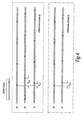
- Figure 4 shows how the time differences, d i,j , between the local base station 'a' and the neighbouring base stations 'b' and 'c' are derived from the synchronisation signals.
- the shaded time slot represents the RACH which can carry synchronisation signals.
- the upper boxed area represents the time differences at base 'a': from top to bottom the lines represent: a) the base station's own signal; b) the delayed signal from base station 'b'; and c) the delayed signal from base station 'c'.
- the lower boxed area represents the time differences at base 'b'. There is no line corresponding to base station 'c' - as would be the case when 'c' was out of range of the signal from 'b'.
- a base station which conforms to the UTRA TDD mode.
- the base station uses the RACH to synchronise with other base stations which are within transmission range.
- the base station is arranged to 'steal' the RACH time slot for transmissions to other base stations at suitable times.
- the times at which a base station should steal a RACH time slot can be determined according to the following criteria:
- the base station When the base station has a schedule assigned for RACH stealing in the near future, at a suitable time it makes a broadcast transmission (preferably on its broadcast control channel, BCCH) to all mobile stations affiliated to the base station, to instruct these mobile stations that the RACH will be unavailable for mobile station transmissions in the forthcoming scheduled stolen RACH time slot. This will clear the stolen RACH time slot for inter cell synchronisation usage.
- BCCH broadcast control channel
- Arranging for the stealing base station to silence mobile stations affiliated to the stealing base station when the RACH is stolen, will prevent unnecessary collisions on the RACH channel.
- the neighbouring base stations will not silence their respective affiliated mobile stations from making RACH transmissions.
- These RACH transmissions will be power controlled and it should be possible for the neighbouring base stations to receive the transmission from the base station stealing the RACH timeslot and to receive any RACH transmissions from their own affiliated mobile stations.
- stolen RACH timeslots are scheduled by the RNC, it is optionally possible to arrange for the neighbouring base stations to silence RACH transmissions from their mobile stations using the same procedure as described for the RACH time slot stealing.
- interference to the synchronisation transmission can be substantially removed, except from distant stations. If this option is not employed then interference to the reception of synchronisation transmission in the RACH timeslot may prevent its reception. However, given the statistics of RACH traffic, a high proportion of such measurements should be received.
- RACH slots are arranged throughout the network of base stations to be allocated to synchronisation at regular fixed intervals. During these allocated RACH slots, none of the mobile stations make RACH transmissions, and it is unnecessary to instruct the mobile stations not to make the RACH transmissions since they are capable of determining such times for themselves. However, the base stations do transmit a simple binary signal periodically to indicate that this mode of operation applies: such a transmission would not be necessary in a network where all base stations had associated GPS receivers. In consequence, during the allocated RACH time slots all base stations are either listening for synchronisation transmissions or making them.
- the subset of base stations making synchronisation transmissions changes from one selected RACH time slot to the next. It is necessary to ensure that the spread of transmissions is such that only one dominant synchronisation signal is received at any given base station in any given selected RACH time slot.
- the planning of these subsets can be performed either manually or automatically according to scheme similar to dynamic channel assignment (DCA).
- bursts are transmitted within time slots and each burst is sub-divided into 2560 chips which are zoned into two data fields, one midamble field and a guard period.
- the midamble field contains training sequences. Because the base stations are static and have accurate frequency references, it is possible to perform correlation across the entire time slot. Correlation makes use of training sequences so the synchronisation burst, with the exception of the guard period, is arranged to have no data fields and effectively becomes all midamble.
- Whole time slot correlation affords a processing gain of about 34dB. This high processing gain serves to compensate for the increased path loss to the neighbouring cells.
- the first and second embodiments of the invention detail methods of gaining access to RACH timeslots. Either embodiment can be implemented according to the distributed or centralised approaches.
- every base station acts autonomously on the basis of the information it has received to adjust its clock timing in such a way that, given that all other base stations operate similarly, they will come into synchronisation.
- each base station measures the timing of each received synchronisation burst relative to its own timing. This can be viewed as the timing of the received burst relative to the time at which it would make its transmission.
- Each base station is provided with a matched filter, matched to the synchronisation code. When a burst.is received, there will usually be several discrete paths. The earliest significant path will be taken to provide the timing since this is most likely to correspond to the line of sight path if there is one. The following discussion relates to the centralised synchronisation procedure, following coarse level synchronisation.
- each base station in the telecommunications system can be synchronised with every other base station.
- synchronisation is important in locating mobile stations.
- initial coarse synchronisation can be achieved in a straightforward manner.
- the base stations When a network is commissioned the base stations may be activated in sequence either by manual intervention or under control of the RNC.
- the first base station to be activated becomes the temporary timing master and makes periodic synchronisation burst transmissions in its RACH channel.
- Other base stations, activated later are only allowed to transmit after they have received a synchronisation burst. In this way the network will become synchronised globally. If an individual base station requires re-synchronisation, following a failure and repair, for example, again that base station is not allowed to transmit until it has received a RACH synchronisation burst from at least one other base station. It may then make its own RACH burst transmission, after making a coarse update to its timing from the initial burst.
- Multi-frame synchronisation can be achieved by a number of means.
- the simplest and preferred method is to make the RACH slot which is 'stolen' for synchronisation always be contained in the first frame or any fixed arbitrary numbered frame within a multi-frame.
Description
- The present invention relates to improvements in or relating to mobile telecommunications systems and is more particularly concerned with synchronisation of base stations within a telecommunications system.
- The UMTS terrestrial radio access time division duplex (UTRA TDD) mode is based on a combination of code division multiple access (CDMA) and hybrid time division multiple access (TDMA). UMTS is an acronym for universal mobile telecommunication system as will be understood by persons skilled in the art.
- Reliable operation in the UTRA TDD mode, incorporating the combined TD-CDMA multiple access scheme, requires synchronisation between base stations within a compliant telecommunications system. Moreover the mode also requires the provision of position information for the mobile stations affiliated to each base station. Synchronisation between base stations is also desirable in order to maximise system capacity. To these ends, the synchronisation of base stations must be achieved at the levels of time slots, frames and multi-frames, where a multi-frame is a repeating cycle of a number of frames.
- One known mechanism for synchronising the base stations is to equip each base station with a global positioning system (GPS) receiver. However, this is not always appropriate or even possible; for example, an area of deployment may be shadowed from the GPS constellation of satellites by tall buildings. For this and other reasons, alternative mechanisms for synchronising the base stations are required.
- In an alternative mechanism, the base stations are synchronised over the backhaul network; the network which enables base stations to switch mobile communications into public telephone networks or the internet. However, if this mechanism is implemented according to a packet protocol (for example, internet protocol (IP) or asynchronous transfer mode (ATM)), then synchronisation will only be possible to a coarse accuracy.
- Lagrange et al : "Autonomous inter base station synchronisation via a common. broadcast control channel", Vehicular Techn. Conference 1994, vol 44, pages 1050-1054 discloses a synchronisation method via a broadcast control channel, vehicle is usually an unidirectional channel from base station to mobile station.
- It is therefore an object of the present invention to obviate or at least mitigate the problems of synchronisation of base stations.
- In accordance with the present invention, there is provided a method of providing synchronisation between a plurality of base stations in a telecommunications system, for each base station there is a telecommunications cell within which there is at least one mobile station and for each base station the method comprises the steps of: providing at least one channel for usage in the telecommunications cell; a transmission step, wherein said at least one channel is utilised for transmission of a synchronisation signal, the transmission being from a first base station to those remaining base stations within the telecommunications system which are within transmission range; and a first calculation step, in which a time difference between clock pulses from the first base station and clock pulses transmitted by other base stations within transmission range is calculated.
- Preferably the method has the further steps: a reporting step, in which each of the plurality of base stations reports the time differences calculated in the time difference calculation step to a radio network controller; a second calculation step, wherein a synchronising adjustment corresponding to each base station is calculated from the reported time differences; and an adjusting step, wherein each base station is individually sent the corresponding synchronising adjustment and the clock of the base station concerned is adjusted accordingly.
- Advantageously, each of the plurality of base stations can act autonomously on the basis of information received from the available remaining base stations to adjust the clock timing of that base station.
- The channel utilised for transmission of the synchronisation signal is preferably a random access channel (RACH) which is transmitted at a frequency within a band of frequencies that is provided for communications with mobile stations. The random access channel advantageously comprises a single time slot per TDMA frame. More preferably, the RACH is allocated to transmissions from mobile stations to initiate communications. Preferably, communications are initiated by requesting a resource unit (time slot and CDMA code combination) for uplink usage.
- The method preferably further comprises a scheduling step in which the utilisation of each RACH time slot for base station synchronisation is allocated according to a schedule.
- More preferably, the method further comprises a silencing step in which a second channel is used by the base station to silence mobile station communications in the RACH time slots to allow the transmission of synchronisation transmissions to other base stations. This second channel is most preferably the broadcast control channel (BCCH).
- For a better understanding of the present invention, reference will now be made, by way of example only, to the accompanying drawings in which:-
- Figure 1 shows a schematic diagram of the UTRA TDD mode.
- Figure 2 shows a schematic diagram of one TDMA frame.
- Figure 3 shows a schematic diagram of a network of telecommunication cells.
- Figure 4 shows a schematic diagram of the time differences between the signals from base stations.
-
- In Figure 1, the UTRA TDD mode is illustrated. Information is transmitted in bursts at a certain combination of frequency, time (within a frame 102), and coding.
Frames 102 are divided intotime slots 104 and each time slot is just long enough for a single burst of information. Transmission of information is multiplexed through the use of orthogonal codes (CDMA). The information transmitted within a particular time slot is divided according to these codes: as a result, each burst contains a plurality of independent time slot and code combinations, calledresource units 106. - The UTRA TDD mode uses a scheme called Time Division - Code Division Multiple Access (TD-CDMA). This scheme provides for a random access channel (RACH) which is a
single time slot 104 perTDMA frame 102. The RACH is allocated to transmissions from mobile stations to initiate communications, usually by requesting aresource unit 106 for uplink usage. The RACHcan be utilised for both inter base station synchronisation and for mobile station position location. - A TDMA frame is illustrated in Figure 2. As will be apparent, each
TDMA frame 200 contains a plurality oftime slots 210; fifteen time slots in TDD mode, as shown. - Figure 3 depicts a typical cellular deployment. Each
base station 300 has an associatedcell 320. The range between neighbouringbase stations 300 is roughly double the range from any base station to amobile station 310 at its cell boundary. In an urban deployment, this typically leads to a path loss which is of the order of 12dB greater to the neighbouringbase station 300 than to the cell-edgemobile station 310. On the one hand, thebase station 300 would have a height gain advantage over amobile station 310 at the same location. On the other hand the base station antennas are typically constructed with a 'down tilt' intended to reduce inter cell interference. These opposing effects are of similar magnitude and will tend to cancel, making the 12dB figure a reasonable estimate for the increase in path loss. - Figure 4 shows how the time differences, di,j, between the local base station 'a' and the neighbouring base stations 'b' and 'c' are derived from the synchronisation signals. The shaded time slot represents the RACH which can carry synchronisation signals. The upper boxed area represents the time differences at base 'a': from top to bottom the lines represent: a) the base station's own signal; b) the delayed signal from base station 'b'; and c) the delayed signal from base station 'c'. Similarly the lower boxed area represents the time differences at base 'b'. There is no line corresponding to base station 'c' - as would be the case when 'c' was out of range of the signal from 'b'.
- In the first embodiment of the present invention, there is provided a base station which conforms to the UTRA TDD mode. The base station uses the RACH to synchronise with other base stations which are within transmission range. The base station is arranged to 'steal' the RACH time slot for transmissions to other base stations at suitable times. In this discussion it is assumed that the same time slot will be used for RACH operation in all cells; whilst this assumption is advantageous, it is not essential to the operation of this invention. The times at which a base station should steal a RACH time slot can be determined according to the following criteria:
- Firstly, neighbouring base stations must not steal the RACH time slot in the same frame.
- Secondly, RACH time slots must be stolen frequently enough to maintain overall base station network synchronisation to the required accuracy.
- Lastly, schedules for RACH time slot stealing may be determined either centrally by a radio network controller (RNC) or according to sequence generators resident in the base stations. In the latter case, the sequence generators are arranged in such a way that RACH stealing schedules do not coincide in neighbouring cells. If the RNC is used, it can establish schedules according to this criterion. The schedules may be at regular, pseudo random or constrained random intervals.
-
- When the base station has a schedule assigned for RACH stealing in the near future, at a suitable time it makes a broadcast transmission (preferably on its broadcast control channel, BCCH) to all mobile stations affiliated to the base station, to instruct these mobile stations that the RACH will be unavailable for mobile station transmissions in the forthcoming scheduled stolen RACH time slot. This will clear the stolen RACH time slot for inter cell synchronisation usage.
- Arranging for the stealing base station to silence mobile stations affiliated to the stealing base station when the RACH is stolen, will prevent unnecessary collisions on the RACH channel. However, as described so far, the neighbouring base stations will not silence their respective affiliated mobile stations from making RACH transmissions. These RACH transmissions will be power controlled and it should be possible for the neighbouring base stations to receive the transmission from the base station stealing the RACH timeslot and to receive any RACH transmissions from their own affiliated mobile stations. However, in the case where stolen RACH timeslots are scheduled by the RNC, it is optionally possible to arrange for the neighbouring base stations to silence RACH transmissions from their mobile stations using the same procedure as described for the RACH time slot stealing.
- In this way the interference to the synchronisation transmission can be substantially removed, except from distant stations. If this option is not employed then interference to the reception of synchronisation transmission in the RACH timeslot may prevent its reception. However, given the statistics of RACH traffic, a high proportion of such measurements should be received.
- In the second embodiment of the present invention, an alternative approach to 'stealing' RACH slots for synchronisation is taken. In this approach, RACH slots are arranged throughout the network of base stations to be allocated to synchronisation at regular fixed intervals. During these allocated RACH slots, none of the mobile stations make RACH transmissions, and it is unnecessary to instruct the mobile stations not to make the RACH transmissions since they are capable of determining such times for themselves. However, the base stations do transmit a simple binary signal periodically to indicate that this mode of operation applies: such a transmission would not be necessary in a network where all base stations had associated GPS receivers. In consequence, during the allocated RACH time slots all base stations are either listening for synchronisation transmissions or making them. The subset of base stations making synchronisation transmissions changes from one selected RACH time slot to the next. It is necessary to ensure that the spread of transmissions is such that only one dominant synchronisation signal is received at any given base station in any given selected RACH time slot. The planning of these subsets can be performed either manually or automatically according to scheme similar to dynamic channel assignment (DCA).
- Within UTRA TDD, bursts are transmitted within time slots and each burst is sub-divided into 2560 chips which are zoned into two data fields, one midamble field and a guard period. The midamble field contains training sequences. Because the base stations are static and have accurate frequency references, it is possible to perform correlation across the entire time slot. Correlation makes use of training sequences so the synchronisation burst, with the exception of the guard period, is arranged to have no data fields and effectively becomes all midamble. Whole time slot correlation affords a processing gain of about 34dB. This high processing gain serves to compensate for the increased path loss to the neighbouring cells.
- Assuming that every base station sends and receives synchronisation bursts to and from its neighbouring base stations, all of the information necessary for the network wide synchronisation can be aggregated. This can be used in one of two distinct ways, either distributed or centralised.
- The first and second embodiments of the invention detail methods of gaining access to RACH timeslots. Either embodiment can be implemented according to the distributed or centralised approaches.
- In the distributed approach, every base station acts autonomously on the basis of the information it has received to adjust its clock timing in such a way that, given that all other base stations operate similarly, they will come into synchronisation.
- In the centralised approach, all base stations report their results to the RNC which then computes a set of adjustments and signals these adjustments individually to the relevant base stations. Essentially, each base station measures the timing of each received synchronisation burst relative to its own timing. This can be viewed as the timing of the received burst relative to the time at which it would make its transmission. Each base station is provided with a matched filter, matched to the synchronisation code. When a burst.is received, there will usually be several discrete paths. The earliest significant path will be taken to provide the timing since this is most likely to correspond to the line of sight path if there is one. The following discussion relates to the centralised synchronisation procedure, following coarse level synchronisation.
- Suppose we have a deployment of N base stations. Let the variable L(i,j) = L(j,i) indicate those base stations which are able to hear each other's synchronisation transmissions. If base station i can hear base station j's transmission and base station j can hear base station i's transmission then L(i,j) = L(j,i) = 1. Otherwise L(i,j) = L(j,i) = 0. Note that L(i,i) = 0 for all i. All relative timings are aggregated at the RNC. If base station i hears base station j's transmission with delay d i,j and base station j hears base station i's transmission with delay d j,i , then the RNC computes the time differences as
- Referring once more to Figure 4, it is plain that L(a,b) = L(b,a) = 1 and L(a,c) = L(c,a) = 1 but L(b,c) = L(c,b) = 0. Figure 4 also illustrates how the time differences, d i,j , are derived. Thus δ i,j is the time by which base station i's time is advanced with respect to the time of base station j and excludes any time delay due to intervening distance.
- Suppose base station i will be retarded by a compensation amount C i which is to be computed. Following such compensation, the new timing error between base stations i and j will be given by
- If all measurements were completely accurate and consistent, we could simply solve the equations to make δ ' / i,j ≡ 0 for all i and all j.
- However, given measurement errors it is better to solve for a minimum sum square error, that is,should be minimised. Expanding this gives:-


- Letbe the number of base stations whose synchronisation transmissions base station i can hear and who can also hear base station i's synchronisation transmission. We can then express the sum square error as


- Now differentiate with respect to C i and equate to zero. We obtainThus


- We can express this in matrix notation as
diag(M) is the diagonal matrix with elements M (i), i∈ {1...N} along the diagonal,
L is the matrix with elements L(i,j),
C is the vector with elements Ci, and
D is a vector with elementswhere S j (i), j ∈ {1...M (i)} is the set of indices of base stations to and from which base station i can send and receive synchronisation transmissions respectively.
- This matrix is singular, i.e. has no inverse. This reflects the fact that any common value can be added to all compensation values, C i , without affecting the sum square error. A reasonable constraint to apply to the compensation values is that their sum should be zero so as to minimise the overall drift. Thus, we have an additional equation:-

- This can be reflected in the matrix equation by adding a row of ones to any of the rows in A to form A'.
- We can now solve the equation to obtain the compensation values. However, we can note that A (and therefore A') does not change very rapidly, if at all, since it is a function only of the base station connectivity. Thus, it may be more efficient to compute the inverse of A' which need only be updated infrequently. We thus obtain:-
- Having these compensation values, C;, each base station in the telecommunications system can be synchronised with every other base station. In addition to fulfilling the requirements of UTRA TDD mode, synchronisation is important in locating mobile stations.
- So far the discussion of synchronisation has covered only fine synchronisation after coarse synchronisation has already been achieved.
- With an RNC in control, initial coarse synchronisation can be achieved in a straightforward manner. When a network is commissioned the base stations may be activated in sequence either by manual intervention or under control of the RNC. The first base station to be activated becomes the temporary timing master and makes periodic synchronisation burst transmissions in its RACH channel. Other base stations, activated later are only allowed to transmit after they have received a synchronisation burst. In this way the network will become synchronised globally. If an individual base station requires re-synchronisation, following a failure and repair, for example, again that base station is not allowed to transmit until it has received a RACH synchronisation burst from at least one other base station. It may then make its own RACH burst transmission, after making a coarse update to its timing from the initial burst.
- The above achieves slot and frame synchronisation since the RACH slot is in a fixed position within the frame. Multi-frame synchronisation can be achieved by a number of means. The simplest and preferred method is to make the RACH slot which is 'stolen' for synchronisation always be contained in the first frame or any fixed arbitrary numbered frame within a multi-frame.
- None of the above description precludes the incorporation of base stations equipped with a GPS receiver. In this case, the compensation values, Ci, for those base stations are set equal to zero and the constraint that the sum of compensation values equals zero is removed. In this way, the synchronisation scheme will cause all of the base stations involved to become synchronised either directly or indirectly to GPS.
Claims (10)
- A method of providing synchronisation between a plurality of base stations (300) in a telecommunications system, the telecommunications system comprising a plurality of cells (320), each of the plurality of cells having one of the plurality of base stations and at least one mobile station (310), the method comprising the steps of:a) providing a random access channel transmitted at a frequency within a band of frequencies that is provided for communications with mobile stations, comprising time slots (210) for usage in the plurality of cells;b) transmitting a synchronisation signal in a given time slot of the random access channel, the transmission being from each of the plurality of base stations to those remaining base stations within the telecommunications system which are within transmission range of each respective base station;c) for each respective base station, calculating respective time differences (d a,b , d a,c ) between corresponding synchronisation signals transmitted by the respective base station and received from other base stations within transmission range of the respective base station; andd) adjusting the timing of the synchronisation signals for the respective base station according to the calculated time differences.
- A method according to Claim 1, wherein the random access channel comprises a time slot per TDMA frame.
- A method according to Claim 2, wherein the random access channel is allocated to uplink transmissions in order to initiate communications.
- A method according to Claim 3, wherein communications are initiated by requesting a resource unit for uplink usage.
- A method according to any preceding claim, having the further steps of:e) for each of the plurality of base stations, reporting the time differences calculated in step c) to a radio network controller;f) calculating a synchronising adjustment corresponding to each base station from the reported time differences;g) informing each base station individually of the corresponding synchronising adjustment calculated in step f); andh) synchronising each base station according to the corresponding synchronising adjustment.
- A method according to any of claims 1-4, having the further step of:j) each respective base station acts autonomously on the time differences calculated in step c) by adjusting its synchronisation to minimise the time differences.
- A method according to any of Claims 2-6, having the further step of:i) allocating the utilisation of each random access channel time slot for base station synchronisation according to a schedule.
- A method according to any one of Claims 2-6, having the further step of:k) using a further channel to silence uplink communications in the random access channel time slots to allow the transmission of synchronisation transmissions from the respective base station to other base stations.
- A method according to Claim 8, wherein the further channel is the broadcast control channel.
- A method according to any preceding claim, wherein the random access channel time slot used is always contained in a fixed numbered frame within a plurality of multi-frames in order to synchronise the plurality of base stations over multi-frames.
Applications Claiming Priority (5)
| Application Number | Priority Date | Filing Date | Title |
|---|---|---|---|
| GB9919973 | 1999-08-24 | ||
| GBGB9919973.9A GB9919973D0 (en) | 1999-08-24 | 1999-08-24 | Improvements in or relating to mobile telecommunications systems |
| GB0007143 | 2000-03-24 | ||
| GB0007143A GB2353671B (en) | 1999-08-24 | 2000-03-24 | Improvements in or relating to mobile telecommunications systems |
| PCT/GB2000/003111 WO2001015340A1 (en) | 1999-08-24 | 2000-08-11 | Method for synchronizing base stations in a mobile communication system |
Publications (2)
| Publication Number | Publication Date |
|---|---|
| EP1206849A1 EP1206849A1 (en) | 2002-05-22 |
| EP1206849B1 true EP1206849B1 (en) | 2005-11-23 |
Family
ID=26243952
Family Applications (1)
| Application Number | Title | Priority Date | Filing Date |
|---|---|---|---|
| EP00951751A Expired - Lifetime EP1206849B1 (en) | 1999-08-24 | 2000-08-11 | Method for synchronizing base stations in a mobile communication system |
Country Status (8)
| Country | Link |
|---|---|
| US (1) | US7110781B1 (en) |
| EP (1) | EP1206849B1 (en) |
| JP (1) | JP2003507957A (en) |
| CN (1) | CN1210894C (en) |
| DE (1) | DE60024276D1 (en) |
| ES (1) | ES2250168T3 (en) |
| GB (1) | GB2386801B (en) |
| WO (1) | WO2001015340A1 (en) |
Cited By (1)
| Publication number | Priority date | Publication date | Assignee | Title |
|---|---|---|---|---|
| US11832202B2 (en) | 2018-08-03 | 2023-11-28 | Huawei Technologies Co., Ltd. | Clock state detection method and apparatus |
Families Citing this family (44)
| Publication number | Priority date | Publication date | Assignee | Title |
|---|---|---|---|---|
| US6674787B1 (en) * | 1999-05-19 | 2004-01-06 | Interdigital Technology Corporation | Raising random access channel packet payload |
| DE10125013A1 (en) * | 2001-05-22 | 2002-11-28 | Siemens Ag | Base stations synchronization in radio communication system, involves adjacent base station sending synchronization sequence always in equal time slot |
| US6861982B2 (en) | 2001-08-16 | 2005-03-01 | Itt Manufacturing Enterprises, Inc. | System for determining position of an emitter |
| US7813311B2 (en) * | 2002-02-05 | 2010-10-12 | Interdigital Technology Corporation | Method and apparatus for synchronizing base stations |
| JP3801123B2 (en) | 2002-09-06 | 2006-07-26 | 株式会社日立製作所 | Wireless system, server and base station |
| GB2396272B (en) * | 2002-12-13 | 2004-11-17 | Motorola Inc | Communication system,communication unit and method for synchronising communication therefor |
| DE10331311B4 (en) * | 2003-07-10 | 2008-02-07 | Siemens Ag | Method for synchronizing a radio communication system divided into radio cells |
| US20080285507A1 (en) * | 2004-04-28 | 2008-11-20 | Nortel Networks Limited | Independent Scheduling in a Wireless Network |
| CN100370864C (en) * | 2004-06-17 | 2008-02-20 | 大唐移动通信设备有限公司 | Network element time synchronizing method in mobile communication system |
| JP4527115B2 (en) * | 2004-06-25 | 2010-08-18 | 三菱電機株式会社 | Inter-base station time synchronization method, base station, and timing master device |
| GB2416635A (en) * | 2004-07-23 | 2006-02-01 | Hewlett Packard Development Co | Positioning system |
| CN100421367C (en) * | 2004-07-26 | 2008-09-24 | 华为技术有限公司 | Method for implementing synchronous transmission for base station |
| US8364185B2 (en) * | 2005-04-18 | 2013-01-29 | Samsung Electronics Co., Ltd. | Method and system for synchronizing a clock for an adjacent network to a clock for an overlay network |
| CN101228807B (en) * | 2005-07-26 | 2012-10-10 | 艾利森电话股份有限公司 | Method and device for scheduling for positioning information of user device |
| US8169982B2 (en) | 2005-08-10 | 2012-05-01 | Qualcomm Incorporated | Method and apparatus for creating a fingerprint for a wireless network |
| US20070064665A1 (en) | 2005-08-23 | 2007-03-22 | Interdigital Technology Corporation | Method and apparatus for accessing an uplink random access channel in a single carrier frequency division multiple access system |
| GB0517488D0 (en) * | 2005-08-26 | 2005-10-05 | Univ Bradford | Ad-hoc networking over umts protocol |
| CN101123468B (en) * | 2006-08-08 | 2011-07-20 | 电信科学技术研究院 | A method and system for synchronizing air interface synchronization between base stations |
| CN101123465B (en) * | 2006-08-09 | 2012-07-04 | 上海贝尔阿尔卡特股份有限公司 | Method and device for synchronization of network devices in wireless communication system |
| GB2446847B (en) | 2007-02-02 | 2012-02-22 | Ubiquisys Ltd | Location of Basestation |
| CN101039146A (en) * | 2007-05-15 | 2007-09-19 | 中兴通讯股份有限公司 | Apparatus and method for empty clock synchronization of wireless mobile communication system base station |
| US20090098885A1 (en) | 2007-10-12 | 2009-04-16 | Qualcomm Incorporated | System and method for storing information to locate a femto cell |
| US9253653B2 (en) | 2007-11-09 | 2016-02-02 | Qualcomm Incorporated | Access point configuration based on received access point signals |
| ES2444851T3 (en) * | 2008-05-30 | 2014-02-27 | Vodafone Group Plc | Method, system and device for exchanging data packets in extended area cellular telephone networks |
| JP4719252B2 (en) * | 2008-06-25 | 2011-07-06 | 京セラ株式会社 | Wireless communication system, management apparatus, and wireless communication method |
| US8498258B2 (en) * | 2008-07-01 | 2013-07-30 | Nokia Siemens Networks Oy | Preamble offset for femto base stations |
| EP2154921A1 (en) * | 2008-08-11 | 2010-02-17 | Nokia Siemens Networks OY | Method for transferring a base station of a wireless communication network from a standby mode to a fully activated mode |
| WO2010055367A1 (en) | 2008-11-12 | 2010-05-20 | Nokia Siemens Networks Oy | Structure for ota enb-enb communication |
| WO2010114442A1 (en) * | 2009-04-01 | 2010-10-07 | Telefonaktiebolaget L M Ericsson (Publ) | Method and arrangement for base station synchronisation |
| CN101888696B (en) * | 2009-05-15 | 2012-08-15 | 电信科学技术研究院 | Channel synchronization method, system and device in multicast single frequency network |
| US8838096B2 (en) | 2009-05-29 | 2014-09-16 | Qualcomm Incorporated | Non-macro cell search integrated with macro-cellular RF carrier monitoring |
| JP2010283756A (en) * | 2009-06-08 | 2010-12-16 | Sony Corp | Wireless communication apparatus, communication control device, wireless communication system, wireless communication method and communication control method |
| US8737274B2 (en) * | 2009-09-09 | 2014-05-27 | Lg Electronics Inc. | Scheduling method, MS apparatus using the scheduling method, data transmission method, and BS apparatus using the data transmission method in wireless communication system |
| CN101668333B (en) * | 2009-09-30 | 2012-11-21 | 华为技术有限公司 | Clock synchronization method and base station |
| CN102026363B (en) * | 2009-10-14 | 2013-07-10 | 电信科学技术研究院 | Base station internal synchronization method of hierarchical system and base station |
| EP2339761B1 (en) * | 2009-12-22 | 2012-07-11 | Mitsubishi Electric R&D Centre Europe B.V. | Method for synchronizing nodes |
| US9055527B2 (en) | 2010-05-06 | 2015-06-09 | Telefonaktiebolaget L M Ericsson (Publ) | Method and system for determining a time synchronization offset between radio base stations |
| US8923892B2 (en) | 2010-05-14 | 2014-12-30 | Qualcomm Incorporated | Method and apparatus for updating femtocell proximity information |
| EP2544387B1 (en) * | 2011-07-04 | 2016-03-16 | Mitsubishi Electric R&D Centre Europe B.V. | Methods and devices for performing synchronization and compensating clock drift among communication devices |
| CN102510575B (en) * | 2011-12-09 | 2014-05-14 | 浙江宏睿通信技术有限公司 | Multilevel relay synchronization implementation method based on TDMA (time division multiple access) |
| CN103313381B (en) * | 2013-06-06 | 2016-10-26 | 安徽华东光电技术研究所 | A kind of radio communication transmitting base station synchronous method |
| JP5973967B2 (en) * | 2013-07-19 | 2016-08-23 | 株式会社Nttドコモ | User apparatus, base station, discovery signal reception method, and discovery signal transmission method |
| WO2015084981A1 (en) * | 2013-12-03 | 2015-06-11 | Red Point Positioning Corporation | Method and system to estimate the location of a receiving device |
| US9867004B2 (en) * | 2015-12-23 | 2018-01-09 | Qualcomm Incorporated | Broadcast time-of-departure (TOD) frame format |
Family Cites Families (27)
| Publication number | Priority date | Publication date | Assignee | Title |
|---|---|---|---|---|
| US4812852A (en) | 1987-02-20 | 1989-03-14 | Scientific Development Corporation | Locating system and method |
| SE457184B (en) | 1987-04-03 | 1988-12-05 | Ericsson Telefon Ab L M | PROCEDURES AND EQUIPMENT FOR SYNCHRONIZATION AND TRANSFER OF INFORMATION IN A RADIO COMMUNICATION NETWORK |
| JP2665497B2 (en) | 1988-12-19 | 1997-10-22 | 日本電信電話株式会社 | How to establish synchronization between base stations |
| FR2646302B1 (en) | 1989-04-25 | 1993-01-15 | Matra Communication | PSEUDO-SYNCHRONIZATION METHOD OF A TIME MULTIPLEXED COMMUNICATION NETWORK AND APPLICATIONS |
| DE69018959T2 (en) | 1989-12-27 | 1995-09-21 | Nec Corp | Frame synchronization system between several radio base stations for a TDMA digital mobile communication system. |
| FI86236C (en) | 1990-09-05 | 1992-07-27 | Nokia Mobile Phones Ltd | TIDSANPASSNINGSLOGIK FOER MOBILTELEFON I GSM-SYSTEMET. |
| SE9002920L (en) * | 1990-09-13 | 1992-02-03 | Televerket | PROCEDURES FOR LOCALIZATION IN MOBILE RADIO SYSTEM |
| US5293645A (en) | 1991-10-04 | 1994-03-08 | Sharp Microelectronics Technology, Inc. | Apparatus and method for locating mobile and portable radio terminals in a radio network |
| FI920976A0 (en) | 1992-03-05 | 1992-03-05 | Tecnomen Oy | RADIOSYNKRONISERINGSFOERFARANDE FOER STOEDSTATIONER I ETT SIMULCASTINGNAET. |
| US5317323A (en) * | 1993-03-05 | 1994-05-31 | E-Systems, Inc. | Passive high accuracy geolocation system and method |
| US5448570A (en) | 1993-03-17 | 1995-09-05 | Kyocera Corporation | System for mutual synchronization and monitoring between base stations |
| WO1994028643A1 (en) * | 1993-05-27 | 1994-12-08 | Nokia Telecommunications Oy | Base station for a tdma cellular radio network |
| US5363376A (en) | 1993-07-30 | 1994-11-08 | Bell Communications Research, Inc. | Method and apparatus for synchronizing timing among radio ports in wireless communications systems |
| DE69523746T2 (en) * | 1994-03-25 | 2002-08-01 | Qualcomm Inc | LOCATION DETERMINATION METHOD FOR USE WITH AN ANALOGUE CELLULAR SYSTEM |
| EP0800319A1 (en) * | 1996-04-02 | 1997-10-08 | Hewlett-Packard Company | Locating method for mobile radio systems |
| EP0817405A3 (en) | 1996-06-28 | 2000-07-26 | Nec Corporation | Mobile communication system and control channel setting method in mobile communication system |
| US6606309B1 (en) * | 1996-11-19 | 2003-08-12 | Ericsson Inc. | Time-multiplexed short message acknowledgement systems and methods |
| JPH10190562A (en) | 1996-12-26 | 1998-07-21 | Toshiba Corp | Inter-base station frame synchronizing system of mobile communication system and base station device adapting the same |
| GB2330716A (en) * | 1997-10-27 | 1999-04-28 | Motorola Ltd | Position determination using a reference transmitter |
| AU1792099A (en) * | 1997-12-01 | 1999-06-16 | Telefonaktiebolaget Lm Ericsson (Publ) | Positioning system and method for cellular mobile radio |
| US6243587B1 (en) * | 1997-12-10 | 2001-06-05 | Ericsson Inc. | Method and system for determining position of a mobile transmitter |
| US6134228A (en) * | 1997-12-12 | 2000-10-17 | Telefonaktiebolaget Lm Ericsson (Publ) | Method and system for determining the position of a mobile terminal in a CDMA mobile communications system |
| EP0954122A1 (en) | 1998-04-28 | 1999-11-03 | Siemens Aktiengesellschaft | Method for the management of a radio communication system and such a system |
| DE69941256D1 (en) * | 1998-05-04 | 2009-09-24 | Nokia Corp | METHOD FOR SYNCHRONIZING A BASE STATION NETWORK |
| US6590881B1 (en) * | 1998-12-04 | 2003-07-08 | Qualcomm, Incorporated | Method and apparatus for providing wireless communication system synchronization |
| US6567482B1 (en) * | 1999-03-05 | 2003-05-20 | Telefonaktiebolaget Lm Ericsson (Publ) | Method and apparatus for efficient synchronization in spread spectrum communications |
| US6721299B1 (en) * | 1999-03-15 | 2004-04-13 | Lg Information & Communications, Ltd. | Pilot signals for synchronization and/or channel estimation |
-
2000
- 2000-03-24 GB GB0314794A patent/GB2386801B/en not_active Expired - Lifetime
- 2000-08-11 DE DE60024276T patent/DE60024276D1/en not_active Expired - Lifetime
- 2000-08-11 WO PCT/GB2000/003111 patent/WO2001015340A1/en active IP Right Grant
- 2000-08-11 EP EP00951751A patent/EP1206849B1/en not_active Expired - Lifetime
- 2000-08-11 US US10/069,269 patent/US7110781B1/en not_active Expired - Lifetime
- 2000-08-11 ES ES00951751T patent/ES2250168T3/en not_active Expired - Lifetime
- 2000-08-11 JP JP2001518948A patent/JP2003507957A/en active Pending
- 2000-08-11 CN CN00814640.3A patent/CN1210894C/en not_active Expired - Lifetime
Cited By (1)
| Publication number | Priority date | Publication date | Assignee | Title |
|---|---|---|---|---|
| US11832202B2 (en) | 2018-08-03 | 2023-11-28 | Huawei Technologies Co., Ltd. | Clock state detection method and apparatus |
Also Published As
| Publication number | Publication date |
|---|---|
| CN1382329A (en) | 2002-11-27 |
| GB0314794D0 (en) | 2003-07-30 |
| DE60024276D1 (en) | 2005-12-29 |
| CN1210894C (en) | 2005-07-13 |
| ES2250168T3 (en) | 2006-04-16 |
| WO2001015340A1 (en) | 2001-03-01 |
| US7110781B1 (en) | 2006-09-19 |
| EP1206849A1 (en) | 2002-05-22 |
| WO2001015340A8 (en) | 2001-04-19 |
| GB2386801B (en) | 2004-03-24 |
| JP2003507957A (en) | 2003-02-25 |
| GB2386801A (en) | 2003-09-24 |
Similar Documents
| Publication | Publication Date | Title |
|---|---|---|
| EP1206849B1 (en) | Method for synchronizing base stations in a mobile communication system | |
| KR100893888B1 (en) | Method and apparatus for synchronization base stations | |
| JP4846956B2 (en) | Base station synchronization method in wireless communication system | |
| EP0626769B1 (en) | Network synchronization for cellular TDMA communication using signals from mobile stations in neighboring cells | |
| RU2447617C2 (en) | Method for synchronisation of radio communication system distributed in radio communication cells | |
| EP1902527B1 (en) | Method and system for mitigating co-channel interference | |
| JPH10190562A (en) | Inter-base station frame synchronizing system of mobile communication system and base station device adapting the same | |
| CN101951286B (en) | Position zone-based time division duplex satellite communication uplink signal alignment method | |
| US6845085B1 (en) | Synchronization method for a processing communication satellite | |
| GB2460356A (en) | Wireless communication device, mobile wireless communication control method and wireless station | |
| US6332069B1 (en) | Apparatus and method for grouping carriers to minimize the occurrence of call blocking in a satellite-based communications network | |
| SE502168C2 (en) | Method and apparatus of a radio communication system | |
| EP0920143A1 (en) | Signal characteristics measuring and reporting by a mobile satellite telephone using a stoled burst of a TDMA frame | |
| GB2353671A (en) | Base station synchronisation | |
| CN1836386B (en) | Method for synchronizing a radio communication system that is divided up into radio cells | |
| GB2356774A (en) | Synchronisation of base stations | |
| EP1089464A2 (en) | Synchronization method for a processing communication satellite | |
| WO2003056731A1 (en) | Synchronisation methods for a communications system | |
| MXPA98008522A (en) | Method and apparatus for the wireless communication of multiple access systems of division of the time, that use collector arrangements for the extent of the ftaa |
Legal Events
| Date | Code | Title | Description |
|---|---|---|---|
| PUAI | Public reference made under article 153(3) epc to a published international application that has entered the european phase |
Free format text: ORIGINAL CODE: 0009012 |
|
| 17P | Request for examination filed |
Effective date: 20020131 |
|
| RBV | Designated contracting states (corrected) |
Designated state(s): DE ES FR GB IT |
|
| 17Q | First examination report despatched |
Effective date: 20040809 |
|
| RAP1 | Party data changed (applicant data changed or rights of an application transferred) |
Owner name: SIEMENS AKTIENGESELLSCHAFT |
|
| GRAP | Despatch of communication of intention to grant a patent |
Free format text: ORIGINAL CODE: EPIDOSNIGR1 |
|
| GRAS | Grant fee paid |
Free format text: ORIGINAL CODE: EPIDOSNIGR3 |
|
| GRAA | (expected) grant |
Free format text: ORIGINAL CODE: 0009210 |
|
| AK | Designated contracting states |
Kind code of ref document: B1 Designated state(s): DE ES FR GB IT |
|
| PG25 | Lapsed in a contracting state [announced via postgrant information from national office to epo] |
Ref country code: IT Free format text: LAPSE BECAUSE OF FAILURE TO SUBMIT A TRANSLATION OF THE DESCRIPTION OR TO PAY THE FEE WITHIN THE PRESCRIBED TIME-LIMIT;WARNING: LAPSES OF ITALIAN PATENTS WITH EFFECTIVE DATE BEFORE 2007 MAY HAVE OCCURRED AT ANY TIME BEFORE 2007. THE CORRECT EFFECTIVE DATE MAY BE DIFFERENT FROM THE ONE RECORDED. Effective date: 20051123 |
|
| REG | Reference to a national code |
Ref country code: GB Ref legal event code: FG4D |
|
| REF | Corresponds to: |
Ref document number: 60024276 Country of ref document: DE Date of ref document: 20051229 Kind code of ref document: P |
|
| PG25 | Lapsed in a contracting state [announced via postgrant information from national office to epo] |
Ref country code: DE Free format text: LAPSE BECAUSE OF FAILURE TO SUBMIT A TRANSLATION OF THE DESCRIPTION OR TO PAY THE FEE WITHIN THE PRESCRIBED TIME-LIMIT Effective date: 20060224 |
|
| REG | Reference to a national code |
Ref country code: ES Ref legal event code: FG2A Ref document number: 2250168 Country of ref document: ES Kind code of ref document: T3 |
|
| ET | Fr: translation filed | ||
| PLBE | No opposition filed within time limit |
Free format text: ORIGINAL CODE: 0009261 |
|
| STAA | Information on the status of an ep patent application or granted ep patent |
Free format text: STATUS: NO OPPOSITION FILED WITHIN TIME LIMIT |
|
| 26N | No opposition filed |
Effective date: 20060824 |
|
| GBPC | Gb: european patent ceased through non-payment of renewal fee |
Effective date: 20060811 |
|
| PG25 | Lapsed in a contracting state [announced via postgrant information from national office to epo] |
Ref country code: GB Free format text: LAPSE BECAUSE OF NON-PAYMENT OF DUE FEES Effective date: 20060811 |
|
| REG | Reference to a national code |
Ref country code: FR Ref legal event code: TP |
|
| PGFP | Annual fee paid to national office [announced via postgrant information from national office to epo] |
Ref country code: ES Payment date: 20080828 Year of fee payment: 9 |
|
| PGFP | Annual fee paid to national office [announced via postgrant information from national office to epo] |
Ref country code: FR Payment date: 20080813 Year of fee payment: 9 |
|
| REG | Reference to a national code |
Ref country code: FR Ref legal event code: ST Effective date: 20100430 |
|
| PG25 | Lapsed in a contracting state [announced via postgrant information from national office to epo] |
Ref country code: FR Free format text: LAPSE BECAUSE OF NON-PAYMENT OF DUE FEES Effective date: 20090831 |
|
| REG | Reference to a national code |
Ref country code: ES Ref legal event code: FD2A Effective date: 20090812 |
|
| PG25 | Lapsed in a contracting state [announced via postgrant information from national office to epo] |
Ref country code: ES Free format text: LAPSE BECAUSE OF NON-PAYMENT OF DUE FEES Effective date: 20090812 |