EP1206787B1 - Gas valve safety device - Google Patents
Gas valve safety device Download PDFInfo
- Publication number
- EP1206787B1 EP1206787B1 EP00937161A EP00937161A EP1206787B1 EP 1206787 B1 EP1206787 B1 EP 1206787B1 EP 00937161 A EP00937161 A EP 00937161A EP 00937161 A EP00937161 A EP 00937161A EP 1206787 B1 EP1206787 B1 EP 1206787B1
- Authority
- EP
- European Patent Office
- Prior art keywords
- knob
- gas valve
- gas
- add
- valve
- Prior art date
- Legal status (The legal status is an assumption and is not a legal conclusion. Google has not performed a legal analysis and makes no representation as to the accuracy of the status listed.)
- Expired - Lifetime
Links
- 238000001514 detection method Methods 0.000 claims abstract description 14
- 238000009877 rendering Methods 0.000 claims description 2
- 238000009987 spinning Methods 0.000 abstract 1
- 238000009434 installation Methods 0.000 description 7
- 239000000126 substance Substances 0.000 description 3
- 230000002265 prevention Effects 0.000 description 2
- 239000000779 smoke Substances 0.000 description 2
- 230000004913 activation Effects 0.000 description 1
- 238000010411 cooking Methods 0.000 description 1
- 238000004880 explosion Methods 0.000 description 1
- 239000002360 explosive Substances 0.000 description 1
- 239000007788 liquid Substances 0.000 description 1
- 238000012544 monitoring process Methods 0.000 description 1
- 230000003472 neutralizing effect Effects 0.000 description 1
- 231100000331 toxic Toxicity 0.000 description 1
- 230000002588 toxic effect Effects 0.000 description 1
- 230000000007 visual effect Effects 0.000 description 1
- XLYOFNOQVPJJNP-UHFFFAOYSA-N water Substances O XLYOFNOQVPJJNP-UHFFFAOYSA-N 0.000 description 1
Images


Classifications
-
- G—PHYSICS
- G01—MEASURING; TESTING
- G01M—TESTING STATIC OR DYNAMIC BALANCE OF MACHINES OR STRUCTURES; TESTING OF STRUCTURES OR APPARATUS, NOT OTHERWISE PROVIDED FOR
- G01M3/00—Investigating fluid-tightness of structures
- G01M3/02—Investigating fluid-tightness of structures by using fluid or vacuum
- G01M3/04—Investigating fluid-tightness of structures by using fluid or vacuum by detecting the presence of fluid at the leakage point
- G01M3/16—Investigating fluid-tightness of structures by using fluid or vacuum by detecting the presence of fluid at the leakage point using electric detection means
- G01M3/18—Investigating fluid-tightness of structures by using fluid or vacuum by detecting the presence of fluid at the leakage point using electric detection means for pipes, cables or tubes; for pipe joints or seals; for valves; for welds; for containers, e.g. radiators
-
- F—MECHANICAL ENGINEERING; LIGHTING; HEATING; WEAPONS; BLASTING
- F16—ENGINEERING ELEMENTS AND UNITS; GENERAL MEASURES FOR PRODUCING AND MAINTAINING EFFECTIVE FUNCTIONING OF MACHINES OR INSTALLATIONS; THERMAL INSULATION IN GENERAL
- F16K—VALVES; TAPS; COCKS; ACTUATING-FLOATS; DEVICES FOR VENTING OR AERATING
- F16K31/00—Actuating devices; Operating means; Releasing devices
- F16K31/02—Actuating devices; Operating means; Releasing devices electric; magnetic
- F16K31/06—Actuating devices; Operating means; Releasing devices electric; magnetic using a magnet, e.g. diaphragm valves, cutting off by means of a liquid
- F16K31/10—Actuating devices; Operating means; Releasing devices electric; magnetic using a magnet, e.g. diaphragm valves, cutting off by means of a liquid with additional mechanism between armature and closure member
- F16K31/105—Actuating devices; Operating means; Releasing devices electric; magnetic using a magnet, e.g. diaphragm valves, cutting off by means of a liquid with additional mechanism between armature and closure member for rotating valves
-
- F—MECHANICAL ENGINEERING; LIGHTING; HEATING; WEAPONS; BLASTING
- F16—ENGINEERING ELEMENTS AND UNITS; GENERAL MEASURES FOR PRODUCING AND MAINTAINING EFFECTIVE FUNCTIONING OF MACHINES OR INSTALLATIONS; THERMAL INSULATION IN GENERAL
- F16K—VALVES; TAPS; COCKS; ACTUATING-FLOATS; DEVICES FOR VENTING OR AERATING
- F16K31/00—Actuating devices; Operating means; Releasing devices
- F16K31/44—Mechanical actuating means
- F16K31/56—Mechanical actuating means without stable intermediate position, e.g. with snap action
- F16K31/563—Mechanical actuating means without stable intermediate position, e.g. with snap action for rotating or pivoting valves
-
- F—MECHANICAL ENGINEERING; LIGHTING; HEATING; WEAPONS; BLASTING
- F16—ENGINEERING ELEMENTS AND UNITS; GENERAL MEASURES FOR PRODUCING AND MAINTAINING EFFECTIVE FUNCTIONING OF MACHINES OR INSTALLATIONS; THERMAL INSULATION IN GENERAL
- F16K—VALVES; TAPS; COCKS; ACTUATING-FLOATS; DEVICES FOR VENTING OR AERATING
- F16K31/00—Actuating devices; Operating means; Releasing devices
- F16K31/44—Mechanical actuating means
- F16K31/56—Mechanical actuating means without stable intermediate position, e.g. with snap action
- F16K31/566—Mechanical actuating means without stable intermediate position, e.g. with snap action using a bistable spring device arranged symmetrically around the actuating stem
-
- F—MECHANICAL ENGINEERING; LIGHTING; HEATING; WEAPONS; BLASTING
- F23—COMBUSTION APPARATUS; COMBUSTION PROCESSES
- F23N—REGULATING OR CONTROLLING COMBUSTION
- F23N5/00—Systems for controlling combustion
- F23N5/24—Preventing development of abnormal or undesired conditions, i.e. safety arrangements
- F23N5/245—Preventing development of abnormal or undesired conditions, i.e. safety arrangements using electrical or electromechanical means
-
- G—PHYSICS
- G01—MEASURING; TESTING
- G01M—TESTING STATIC OR DYNAMIC BALANCE OF MACHINES OR STRUCTURES; TESTING OF STRUCTURES OR APPARATUS, NOT OTHERWISE PROVIDED FOR
- G01M3/00—Investigating fluid-tightness of structures
- G01M3/02—Investigating fluid-tightness of structures by using fluid or vacuum
- G01M3/04—Investigating fluid-tightness of structures by using fluid or vacuum by detecting the presence of fluid at the leakage point
- G01M3/20—Investigating fluid-tightness of structures by using fluid or vacuum by detecting the presence of fluid at the leakage point using special tracer materials, e.g. dye, fluorescent material, radioactive material
- G01M3/22—Investigating fluid-tightness of structures by using fluid or vacuum by detecting the presence of fluid at the leakage point using special tracer materials, e.g. dye, fluorescent material, radioactive material for pipes, cables or tubes; for pipe joints or seals; for valves; for welds; for containers, e.g. radiators
-
- F—MECHANICAL ENGINEERING; LIGHTING; HEATING; WEAPONS; BLASTING
- F23—COMBUSTION APPARATUS; COMBUSTION PROCESSES
- F23N—REGULATING OR CONTROLLING COMBUSTION
- F23N2231/00—Fail safe
- F23N2231/18—Detecting fluid leaks
-
- F—MECHANICAL ENGINEERING; LIGHTING; HEATING; WEAPONS; BLASTING
- F23—COMBUSTION APPARATUS; COMBUSTION PROCESSES
- F23N—REGULATING OR CONTROLLING COMBUSTION
- F23N2235/00—Valves, nozzles or pumps
- F23N2235/12—Fuel valves
- F23N2235/14—Fuel valves electromagnetically operated
-
- Y—GENERAL TAGGING OF NEW TECHNOLOGICAL DEVELOPMENTS; GENERAL TAGGING OF CROSS-SECTIONAL TECHNOLOGIES SPANNING OVER SEVERAL SECTIONS OF THE IPC; TECHNICAL SUBJECTS COVERED BY FORMER USPC CROSS-REFERENCE ART COLLECTIONS [XRACs] AND DIGESTS
- Y10—TECHNICAL SUBJECTS COVERED BY FORMER USPC
- Y10T—TECHNICAL SUBJECTS COVERED BY FORMER US CLASSIFICATION
- Y10T137/00—Fluid handling
- Y10T137/1842—Ambient condition change responsive
- Y10T137/1915—Burner gas cutoff
Definitions
- the present invention relates to a safety valve system for the prevention of gas leaks. More particularly it relates to an add-on safety device installed over a previously installed valve controlling the gas flow in a gas pipe, designed to automatically shut off the valve when a gas leak is detected.
- EP 440828 (Gazzaz) a gas monitoring system with leak detection and flow cut off was disclosed for controlling the flow of gas from a pressurized gas container to a cooking range of a kitchen. Leaked gas is detected by a sensor which activates a visual and an audible alarm and which operates said valve to terminate the gas flow.It comprised a valve having a solenoid having an energized position for retaining the valve in an open position allowing gas to flow through the valve and a deenrgized position in which the valve is shut off.
- a safety device for detecting gas leaks comprising a gas detection electronic circuit, which signals electromagnetic waves with radio frequency, at the event of gas leak detection, to a second electronic circuit, and controls a solenoid valve for the opening and closing of the gas supply in said gas system.
- the present invention seeks to provide an add-on safety device that can be mounted on top of an existing gas valve knob and thus eliminate the need to make major changes in an existing gas system.
- the purpose of the gas safety add-on device of the present invention is to provide a reliable, simple to install and to operate, add-on safety device mounted over an existing gas valve, for the controlling of gas supply and the automatic gas supply cut off in the event of gas leak detection.
- an add-on automatic safety gas device for shutting off a gas valve at the detection of a gas leak comprising:
- the fixing means is a clamp.
- the add-on adapter device is housed inside a housing.
- the add-on adapter housing is installed over the gas valve, and the spindle axis of rotation aligned with that of the gas valve handle.
- the add-on adapter device may be operated manually, switching said gas valve from closed position to open position and vice versa.
- the spring is a torsion spring.
- the present invention seeks to provide an add-on adapter switch which can be mounted on an existing gas valve knob, and automatically actuate the closure of said valve upon the detection of gas leak by a gas leak detector.
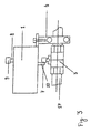
- the gas safety add-on device (generally assigned the numeral 1) comprises an add-on actuator housing (2), mounted over an existing gas valve (3), and fixed in position over said gas valve, by means of a clamp (4).
- a first knob (5) provided with affixing means (6), holds onto the gas valve knob (7), thus enabling joint swiveling of said knobs.
- the first knob (5) is firmly attached to the proximal end of a spindle (8), which is threaded through said housing (2), with said first knob protruding out of said housing, capable of rotating substantially parallely to the axis of rotation of the gas valve knob (7). This is gained by properly positioning the add-on adapter housing (2) over the gas valve (3), and aligning the spindle axis of rotation with that of the gas valve knob, during the installation of the device over the existing gas valve.
- a knob(9) or handle is attached to the distal end of the spindle. The knob (9) may be manually operated to switch the gas valve from “closed” to “open” positions by turning the knob in the appropriate direction.
- the device is further provided with an override mechanism which is designed, upon the event of gas leak detection, to turn off the gas valve, if it is in the open position.
- a second knob (10) rotatably mounted substantially perpendicular to the spindle (8) is coupled to a torsion spring(13), and provided with firm support (11) which is positioned along side the gas valve knob (7).
- the torsion spring (13) is in its deenergized, unwound state, when the second knob (10) is aligned with the "closed position” of the gas valve knob (7), and in its energized, wound state, when the second knob (10) is aligned with the "open position" of the gas valve knob (7).
- the position of the second knob (10) is partially dependant on the position of the gas valve knob (7), so that when the second knob (10) is not aligned parallel to the "open position” alignment of the gas valve knob (7), turning of the gas valve knob (7) to its “open position” causes the second knob (10) to turn and parallely align with the gas valve knob. Accordingly, when the second knob (10) alignment is changed from the “open position” to the “closed position", it causes the gas valve knob (7) to turn, and realign with the second knob (10) in the "closed position".
- the first knob (5) When the user turns the knob (9) to the "open position", the first knob (5) is rotated to the "open position” (usually parallel to the gas pipe), and forces the second (10) to rotate accordingly. The user has to apply force to overcome the resisting force of the torsion spring (13). If the knob (9) is later turned by the user to the "closed position", the second knob (10) remains stationary in its “open position”.
- the second knob (10) is held in place at the "open position” by means of a bracket (14) provided on a plunger (15) inserted in a groove (not showing in Fig. 1) on the second knob (10), facing said bracket.
- the plunger (15) is attached to the core of a solenoid coil (16). When the solenoid coil is in its deenergized position the plunger is resiliently pressed against the second knob (10), forcing the bracket of the plunger (15) into the groove on the second knob (10).
- a gas detector located in the vicinity of the gas valve detects the leak and produces an electric signal, which is transmited via electric wiring and intercepted by an electric circuitry (all not showing in Fig. 1) preferably housed inside said add-on adapter housing (2).
- an electric circuitry preferably housed inside said add-on adapter housing (2).
- the electric circuitry Upon receiving the electric signal the electric circuitry is designed to produce an electric current which energizes the solenoid coil (16), pulling the plunger (15) away from the groove in the second knob (10), and allowing the torsion spring (13) to turn the second knob (10) and consequently the gas valve knob (5) to the "closed position", thus cutting off the gas supply through the gas valve.
- the device may be brought to its "open position” by manually turning the knob (9) to regain the "open position".
- gas valve may at all times be operated manually by turning the knob (9) in the desired direction, and closing or opening it as required.
- Fig. 2 illustrates an add-on safety device (1) in accordance with a preferred embodiment of the present invention, mounted over a standard 90 degrees ball valve (3), and held at "open" position.
- the housing (2) is mounted over the gas valve (3), and kept in position by means of a clamp (4).
- the knob (9) at the top of the spindle (8), here in the form of a handle is rotated to the open position, which is parallel to the gas pipe (17).
- Fig. 3 illustrates an add-on safety device (1) in accordance with a preferred embodiment of the present invention, mounted over a standard 90 degrees ball valve (3), after being actuated to turn the valve handle (7) to its closed position, in the event of gas leak detection. After the gas leak had been taken care of, and the danger cleared, the gas valve may be manually opened, by rotating the knob (9) to the "open position".
Landscapes
- Engineering & Computer Science (AREA)
- General Engineering & Computer Science (AREA)
- Mechanical Engineering (AREA)
- Physics & Mathematics (AREA)
- General Physics & Mathematics (AREA)
- Combustion & Propulsion (AREA)
- Chemical & Material Sciences (AREA)
- Feeding And Controlling Fuel (AREA)
- Emergency Alarm Devices (AREA)
- Fluid-Driven Valves (AREA)
- Regulation And Control Of Combustion (AREA)
- Examining Or Testing Airtightness (AREA)
- Mechanically-Actuated Valves (AREA)
- Indication Of The Valve Opening Or Closing Status (AREA)
- Magnetically Actuated Valves (AREA)
Applications Claiming Priority (3)
| Application Number | Priority Date | Filing Date | Title |
|---|---|---|---|
| IL13065199A IL130651A (en) | 1999-06-27 | 1999-06-27 | Gas valve safety device |
| IL13065199 | 1999-06-27 | ||
| PCT/IL2000/000354 WO2001001432A1 (en) | 1999-06-27 | 2000-06-18 | Gas valve safety device |
Publications (3)
| Publication Number | Publication Date |
|---|---|
| EP1206787A1 EP1206787A1 (en) | 2002-05-22 |
| EP1206787A4 EP1206787A4 (en) | 2002-09-11 |
| EP1206787B1 true EP1206787B1 (en) | 2003-11-19 |
Family
ID=11072969
Family Applications (1)
| Application Number | Title | Priority Date | Filing Date |
|---|---|---|---|
| EP00937161A Expired - Lifetime EP1206787B1 (en) | 1999-06-27 | 2000-06-18 | Gas valve safety device |
Country Status (9)
| Country | Link |
|---|---|
| US (1) | US6170509B1 (enExample) |
| EP (1) | EP1206787B1 (enExample) |
| JP (1) | JP2003503654A (enExample) |
| AT (1) | ATE254800T1 (enExample) |
| AU (1) | AU5244500A (enExample) |
| CA (1) | CA2377885A1 (enExample) |
| DE (1) | DE60006684D1 (enExample) |
| IL (1) | IL130651A (enExample) |
| WO (1) | WO2001001432A1 (enExample) |
Cited By (1)
| Publication number | Priority date | Publication date | Assignee | Title |
|---|---|---|---|---|
| CN112963607A (zh) * | 2021-02-05 | 2021-06-15 | 中国地震局工程力学研究所 | 一种带有双磁路传感器的控制系统 |
Families Citing this family (30)
| Publication number | Priority date | Publication date | Assignee | Title |
|---|---|---|---|---|
| MY121845A (en) * | 1998-09-11 | 2006-02-28 | Panasonic Corp | Gas type identification system |
| GB0030907D0 (en) * | 2000-12-16 | 2001-01-31 | Eco Electronics Dev Co Ltd | Fluid control valves |
| US6374850B1 (en) * | 2001-02-16 | 2002-04-23 | Scott M. Timm | Emergency gas line shut-off system |
| CA2467477A1 (en) * | 2001-11-22 | 2003-06-05 | The Linden Shield Limited | Temperature-sensitive safety valve assembly |
| GB0213936D0 (en) * | 2002-06-18 | 2002-07-31 | Linden Sean J | The solar heat reacting valve |
| US6733276B1 (en) | 2003-03-04 | 2004-05-11 | Jeffrey R. Kopping | Gas shut-off device |
| JP2005045974A (ja) * | 2003-07-25 | 2005-02-17 | Denso Corp | ブラシレスモータ駆動装置 |
| US7604216B2 (en) * | 2006-01-18 | 2009-10-20 | Innovative Technology Concepts, Inc. | Remotely activated manifold shut-off |
| US9016662B2 (en) * | 2006-08-29 | 2015-04-28 | Custom Controls, Llc | Efficient manual to automatic valve conversion device |
| US8931755B2 (en) * | 2006-08-29 | 2015-01-13 | Custom Controls, Llc | Manual to automatic valve conversion device |
| US8172198B2 (en) * | 2007-08-09 | 2012-05-08 | Goodrich Corporation | Valve assembly for aircraft water supply system |
| US20100000612A1 (en) * | 2007-12-07 | 2010-01-07 | Innovative Technology Concepts, Inc. | Remotely activated manifold shut-off and method of using the same |
| GB2477776A (en) * | 2010-02-12 | 2011-08-17 | Haven Ltd | Valve with leak detector |
| US20130134342A1 (en) * | 2011-11-26 | 2013-05-30 | Jesse Shiffer | Gas safety valve |
| JP6463462B2 (ja) * | 2014-08-19 | 2019-02-06 | マイヤー インテレクチュアル プロパティーズ リミテッド | 高度調理器具による自動調理制御 |
| KR200480570Y1 (ko) * | 2015-01-28 | 2016-06-10 | 후이-밍 린 | 전기식 가스 차단 밸브 |
| PT108670B (pt) * | 2015-07-07 | 2020-10-14 | Epal - Empresa Portuguesa Das Águas Livres, S.A. | Sistema anti-fuga para um circuito de doseamento de gases/líquidos |
| US9671031B2 (en) * | 2015-11-01 | 2017-06-06 | Mordechai Ben Old | Wireless electric valve for automatic closing and opening of main fluid pipe |
| CN108431475B (zh) | 2015-12-22 | 2019-12-20 | 韦克斯曼消费产品集团有限公司 | 水阀关闭系统 |
| US11766151B2 (en) | 2016-02-18 | 2023-09-26 | Meyer Intellectual Properties Ltd. | Cooking system with error detection |
| EP3416529A4 (en) | 2016-02-18 | 2019-08-21 | Meyer Intellectual Properties Limited | ADDITIONAL BUTTON FOR A COOKING SYSTEM |
| WO2017162189A1 (zh) * | 2016-03-25 | 2017-09-28 | 时代大陆机电科技(大连)有限公司 | 电磁阀装置 |
| PE20191559A1 (es) * | 2017-02-08 | 2019-10-25 | Mark Eugene Bishoff | Valvula de cierre para un circuito de fluido y metodo para operar la misma |
| US10876277B1 (en) | 2019-01-04 | 2020-12-29 | Mohammad Taghi Fatehi | Automatic seismic wave detector and valve controller |
| US10718442B1 (en) | 2019-01-04 | 2020-07-21 | Mohammad Taghi Fatehi | Retrofit automatic seismic wave detector and valve shutoff device |
| US10982789B2 (en) * | 2019-02-14 | 2021-04-20 | Sensus Spectrum, Llc | Gas meters having high pressure shut-off valves and related gas flow control systems |
| CN110261050B (zh) * | 2019-07-31 | 2021-07-27 | 中国船舶科学研究中心(中国船舶重工集团公司第七0二研究所) | 一种基于阀杆扭矩变化蝶阀密封性能监测装置和监测方法 |
| US11112809B1 (en) | 2020-02-28 | 2021-09-07 | Michael Bafaro | Gas alarm and safety system and method |
| US20230243509A1 (en) * | 2020-06-13 | 2023-08-03 | Butterfly Gandhimathi Appliances Limited | Safety knobs for gas cooktops |
| CN116085688B (zh) * | 2023-02-08 | 2025-12-09 | 保一集团有限公司 | 一种多功能燃气管道智能安全阀系统 |
Family Cites Families (19)
| Publication number | Priority date | Publication date | Assignee | Title |
|---|---|---|---|---|
| US118008A (en) * | 1871-08-15 | Improvement in apparatus for automatically operating gas-cocks | ||
| US2333370A (en) * | 1940-09-16 | 1943-11-02 | Stanley W Graham | Automatic shutoff |
| US3085781A (en) * | 1962-01-15 | 1963-04-16 | R & A Machine Company Inc | Valve actuator |
| US3685790A (en) * | 1971-04-30 | 1972-08-22 | Maxon Corp | Valve actuating mechanism |
| USRE30135E (en) * | 1973-02-09 | 1979-11-06 | Amelia Inc. | Electric fail-safe actuator |
| US3923475A (en) * | 1973-10-25 | 1975-12-02 | Waukee Eng Co | Firecheck |
| US3955186A (en) * | 1974-05-17 | 1976-05-04 | Compugraphic Corporation | Character image generation apparatus and CRT phototypesetting system |
| JPS54114843U (enExample) * | 1978-02-01 | 1979-08-11 | ||
| US4533114A (en) * | 1983-02-08 | 1985-08-06 | Posi-Seal International, Inc. | Fail-safe actuator for rotary valves |
| US4488567A (en) * | 1983-07-05 | 1984-12-18 | Grant Willie T | Automatic valve closer |
| ES279457Y (es) | 1984-05-24 | 1985-06-16 | Bouzas Fuentetaja Julio | Valvula de paso de interrupcion automatica del suministro para caso de fugas de gas |
| JPS61177266U (enExample) * | 1985-04-24 | 1986-11-05 | ||
| US4637423A (en) * | 1985-09-27 | 1987-01-20 | Gray David K | Pneumatic gas cylinder valve actuator |
| US4916437A (en) | 1987-08-14 | 1990-04-10 | Gazzaz Hesham H | Gas monitoring system with leak detection and flow cutoff |
| IT1253111B (it) | 1991-07-15 | 1995-07-10 | Dispositivo di sicurezza contro le fughe di gas. | |
| GB9205876D0 (en) * | 1992-03-18 | 1992-04-29 | Ici Plc | Valve closing mechanism |
| US5409037A (en) * | 1994-06-06 | 1995-04-25 | Wheeler; Jaye F. | Automatic device for the detection and shutoff of excess water flow in pipes |
| US5632302A (en) * | 1995-12-22 | 1997-05-27 | Lenoir, Jr.; Robert M. | Overflow protection shut-off apparatus for use with a water heater |
| US5967171A (en) * | 1996-08-22 | 1999-10-19 | Dwyer, Jr.; George W. | Shut-off system for preventing water damage |
-
1999
- 1999-06-27 IL IL13065199A patent/IL130651A/en not_active IP Right Cessation
- 1999-10-19 US US09/421,174 patent/US6170509B1/en not_active Expired - Fee Related
-
2000
- 2000-06-18 CA CA002377885A patent/CA2377885A1/en not_active Abandoned
- 2000-06-18 WO PCT/IL2000/000354 patent/WO2001001432A1/en not_active Ceased
- 2000-06-18 AT AT00937161T patent/ATE254800T1/de not_active IP Right Cessation
- 2000-06-18 AU AU52445/00A patent/AU5244500A/en not_active Abandoned
- 2000-06-18 EP EP00937161A patent/EP1206787B1/en not_active Expired - Lifetime
- 2000-06-18 JP JP2001506563A patent/JP2003503654A/ja active Pending
- 2000-06-18 DE DE60006684T patent/DE60006684D1/de not_active Expired - Lifetime
Cited By (1)
| Publication number | Priority date | Publication date | Assignee | Title |
|---|---|---|---|---|
| CN112963607A (zh) * | 2021-02-05 | 2021-06-15 | 中国地震局工程力学研究所 | 一种带有双磁路传感器的控制系统 |
Also Published As
| Publication number | Publication date |
|---|---|
| ATE254800T1 (de) | 2003-12-15 |
| JP2003503654A (ja) | 2003-01-28 |
| WO2001001432A1 (en) | 2001-01-04 |
| US6170509B1 (en) | 2001-01-09 |
| DE60006684D1 (de) | 2003-12-24 |
| IL130651A0 (en) | 2001-04-30 |
| AU5244500A (en) | 2001-01-31 |
| IL130651A (en) | 2002-02-10 |
| EP1206787A1 (en) | 2002-05-22 |
| CA2377885A1 (en) | 2001-01-04 |
| EP1206787A4 (en) | 2002-09-11 |
Similar Documents
| Publication | Publication Date | Title |
|---|---|---|
| EP1206787B1 (en) | Gas valve safety device | |
| US7137408B2 (en) | Universal valve switch | |
| US4916437A (en) | Gas monitoring system with leak detection and flow cutoff | |
| EP1079684B1 (en) | System for controlling fluid flow | |
| US4998434A (en) | Gas leakage detector | |
| US5694960A (en) | Hazardous gas protection system and method for automatic valve closure | |
| US4895018A (en) | Gas leakage detector | |
| KR100359624B1 (ko) | 전자식 타이머에 의한 개방시간이 조절가능한 밸브 조립체 | |
| US5078172A (en) | Seismic actuator | |
| JPH08117357A (ja) | 流水検知装置 | |
| WO1986000970A1 (en) | Sensing of fire installation water valves being closed | |
| US5035195A (en) | Valve shut-off flag | |
| EP0793042A1 (en) | Safety valve arrangement | |
| JP2532844B2 (ja) | ガス事故防止システム | |
| KR100240512B1 (ko) | 가스 공급 차단 장치 | |
| KR100366006B1 (ko) | 영구자석을 가스측에 내장한 비접촉식 전자가스밸브 | |
| JP2581573B2 (ja) | ガス洩れ事故防止装置 | |
| KR100715494B1 (ko) | 가스 누설경보 차단시스템 | |
| JPH10263108A (ja) | スプリンクラ消火設備 | |
| JPH01263412A (ja) | ガス安全装置 | |
| KR100388781B1 (ko) | 광섬유 케이블을 내장하는 가스 호스 및 이를 이용한원격제어되는 가스 안전시스템 | |
| TR202100327U5 (tr) | Güvenli̇k ci̇hazi | |
| AU567040B2 (en) | Sensing of fire installation water valves being closed | |
| BR102020005251A2 (pt) | sistema eletrônico de controle de alimentação de gás | |
| JPS6141002Y2 (enExample) |
Legal Events
| Date | Code | Title | Description |
|---|---|---|---|
| PUAI | Public reference made under article 153(3) epc to a published international application that has entered the european phase |
Free format text: ORIGINAL CODE: 0009012 |
|
| 17P | Request for examination filed |
Effective date: 20020125 |
|
| AX | Request for extension of the european patent |
Free format text: AL;LT;LV;MK;RO;SI |
|
| A4 | Supplementary search report drawn up and despatched |
Effective date: 20020726 |
|
| AK | Designated contracting states |
Kind code of ref document: A4 Designated state(s): AT BE CH CY DE DK ES FI FR GB GR IE IT LI LU MC NL PT SE |
|
| RIC1 | Information provided on ipc code assigned before grant |
Free format text: 7H 01H 35/00 A, 7F 16K 37/00 B, 7F 16K 31/56 B, 7F 16K 17/36 B |
|
| GRAH | Despatch of communication of intention to grant a patent |
Free format text: ORIGINAL CODE: EPIDOS IGRA |
|
| GRAS | Grant fee paid |
Free format text: ORIGINAL CODE: EPIDOSNIGR3 |
|
| GRAA | (expected) grant |
Free format text: ORIGINAL CODE: 0009210 |
|
| AK | Designated contracting states |
Kind code of ref document: B1 Designated state(s): AT BE CH CY DE DK ES FI FR GB GR IE IT LI LU MC NL PT SE |
|
| PG25 | Lapsed in a contracting state [announced via postgrant information from national office to epo] |
Ref country code: FI Free format text: LAPSE BECAUSE OF FAILURE TO SUBMIT A TRANSLATION OF THE DESCRIPTION OR TO PAY THE FEE WITHIN THE PRESCRIBED TIME-LIMIT Effective date: 20031119 Ref country code: AT Free format text: LAPSE BECAUSE OF FAILURE TO SUBMIT A TRANSLATION OF THE DESCRIPTION OR TO PAY THE FEE WITHIN THE PRESCRIBED TIME-LIMIT Effective date: 20031119 Ref country code: CH Free format text: LAPSE BECAUSE OF FAILURE TO SUBMIT A TRANSLATION OF THE DESCRIPTION OR TO PAY THE FEE WITHIN THE PRESCRIBED TIME-LIMIT Effective date: 20031119 Ref country code: LI Free format text: LAPSE BECAUSE OF FAILURE TO SUBMIT A TRANSLATION OF THE DESCRIPTION OR TO PAY THE FEE WITHIN THE PRESCRIBED TIME-LIMIT Effective date: 20031119 Ref country code: CY Free format text: LAPSE BECAUSE OF FAILURE TO SUBMIT A TRANSLATION OF THE DESCRIPTION OR TO PAY THE FEE WITHIN THE PRESCRIBED TIME-LIMIT Effective date: 20031119 Ref country code: BE Free format text: LAPSE BECAUSE OF FAILURE TO SUBMIT A TRANSLATION OF THE DESCRIPTION OR TO PAY THE FEE WITHIN THE PRESCRIBED TIME-LIMIT Effective date: 20031119 |
|
| REG | Reference to a national code |
Ref country code: GB Ref legal event code: FG4D |
|
| REG | Reference to a national code |
Ref country code: CH Ref legal event code: EP |
|
| REF | Corresponds to: |
Ref document number: 60006684 Country of ref document: DE Date of ref document: 20031224 Kind code of ref document: P |
|
| REG | Reference to a national code |
Ref country code: IE Ref legal event code: FG4D |
|
| PG25 | Lapsed in a contracting state [announced via postgrant information from national office to epo] |
Ref country code: GR Free format text: LAPSE BECAUSE OF FAILURE TO SUBMIT A TRANSLATION OF THE DESCRIPTION OR TO PAY THE FEE WITHIN THE PRESCRIBED TIME-LIMIT Effective date: 20040219 Ref country code: DK Free format text: LAPSE BECAUSE OF FAILURE TO SUBMIT A TRANSLATION OF THE DESCRIPTION OR TO PAY THE FEE WITHIN THE PRESCRIBED TIME-LIMIT Effective date: 20040219 Ref country code: SE Free format text: LAPSE BECAUSE OF FAILURE TO SUBMIT A TRANSLATION OF THE DESCRIPTION OR TO PAY THE FEE WITHIN THE PRESCRIBED TIME-LIMIT Effective date: 20040219 |
|
| PG25 | Lapsed in a contracting state [announced via postgrant information from national office to epo] |
Ref country code: DE Free format text: LAPSE BECAUSE OF FAILURE TO SUBMIT A TRANSLATION OF THE DESCRIPTION OR TO PAY THE FEE WITHIN THE PRESCRIBED TIME-LIMIT Effective date: 20040220 |
|
| PG25 | Lapsed in a contracting state [announced via postgrant information from national office to epo] |
Ref country code: ES Free format text: LAPSE BECAUSE OF FAILURE TO SUBMIT A TRANSLATION OF THE DESCRIPTION OR TO PAY THE FEE WITHIN THE PRESCRIBED TIME-LIMIT Effective date: 20040302 |
|
| LTIE | Lt: invalidation of european patent or patent extension |
Effective date: 20031119 |
|
| REG | Reference to a national code |
Ref country code: CH Ref legal event code: PL |
|
| PG25 | Lapsed in a contracting state [announced via postgrant information from national office to epo] |
Ref country code: LU Free format text: LAPSE BECAUSE OF NON-PAYMENT OF DUE FEES Effective date: 20040618 |
|
| PG25 | Lapsed in a contracting state [announced via postgrant information from national office to epo] |
Ref country code: MC Free format text: LAPSE BECAUSE OF NON-PAYMENT OF DUE FEES Effective date: 20040630 |
|
| ET | Fr: translation filed | ||
| PLBE | No opposition filed within time limit |
Free format text: ORIGINAL CODE: 0009261 |
|
| STAA | Information on the status of an ep patent application or granted ep patent |
Free format text: STATUS: NO OPPOSITION FILED WITHIN TIME LIMIT |
|
| 26N | No opposition filed |
Effective date: 20040820 |
|
| PG25 | Lapsed in a contracting state [announced via postgrant information from national office to epo] |
Ref country code: PT Free format text: LAPSE BECAUSE OF NON-PAYMENT OF DUE FEES Effective date: 20040419 |
|
| PGFP | Annual fee paid to national office [announced via postgrant information from national office to epo] |
Ref country code: NL Payment date: 20090625 Year of fee payment: 10 Ref country code: IE Payment date: 20090629 Year of fee payment: 10 |
|
| PGFP | Annual fee paid to national office [announced via postgrant information from national office to epo] |
Ref country code: IT Payment date: 20090626 Year of fee payment: 10 |
|
| PGFP | Annual fee paid to national office [announced via postgrant information from national office to epo] |
Ref country code: FR Payment date: 20090630 Year of fee payment: 10 |
|
| PGFP | Annual fee paid to national office [announced via postgrant information from national office to epo] |
Ref country code: GB Payment date: 20090626 Year of fee payment: 10 |
|
| REG | Reference to a national code |
Ref country code: NL Ref legal event code: V1 Effective date: 20110101 |
|
| GBPC | Gb: european patent ceased through non-payment of renewal fee |
Effective date: 20100618 |
|
| REG | Reference to a national code |
Ref country code: FR Ref legal event code: ST Effective date: 20110228 |
|
| REG | Reference to a national code |
Ref country code: IE Ref legal event code: MM4A |
|
| PG25 | Lapsed in a contracting state [announced via postgrant information from national office to epo] |
Ref country code: IT Free format text: LAPSE BECAUSE OF NON-PAYMENT OF DUE FEES Effective date: 20100618 |
|
| PG25 | Lapsed in a contracting state [announced via postgrant information from national office to epo] |
Ref country code: IE Free format text: LAPSE BECAUSE OF NON-PAYMENT OF DUE FEES Effective date: 20100618 |
|
| PG25 | Lapsed in a contracting state [announced via postgrant information from national office to epo] |
Ref country code: NL Free format text: LAPSE BECAUSE OF NON-PAYMENT OF DUE FEES Effective date: 20110101 Ref country code: FR Free format text: LAPSE BECAUSE OF NON-PAYMENT OF DUE FEES Effective date: 20100630 |
|
| PG25 | Lapsed in a contracting state [announced via postgrant information from national office to epo] |
Ref country code: GB Free format text: LAPSE BECAUSE OF NON-PAYMENT OF DUE FEES Effective date: 20100618 |