EP1206615B1 - A device for damping movements of structural elements and a bracing system - Google Patents
A device for damping movements of structural elements and a bracing system Download PDFInfo
- Publication number
- EP1206615B1 EP1206615B1 EP00951267A EP00951267A EP1206615B1 EP 1206615 B1 EP1206615 B1 EP 1206615B1 EP 00951267 A EP00951267 A EP 00951267A EP 00951267 A EP00951267 A EP 00951267A EP 1206615 B1 EP1206615 B1 EP 1206615B1
- Authority
- EP
- European Patent Office
- Prior art keywords
- members
- damper
- structural elements
- frictional
- side plates
- Prior art date
- Legal status (The legal status is an assumption and is not a legal conclusion. Google has not performed a legal analysis and makes no representation as to the accuracy of the status listed.)
- Expired - Lifetime
Links
Images


Classifications
-
- E—FIXED CONSTRUCTIONS
- E04—BUILDING
- E04H—BUILDINGS OR LIKE STRUCTURES FOR PARTICULAR PURPOSES; SWIMMING OR SPLASH BATHS OR POOLS; MASTS; FENCING; TENTS OR CANOPIES, IN GENERAL
- E04H9/00—Buildings, groups of buildings or shelters adapted to withstand or provide protection against abnormal external influences, e.g. war-like action, earthquake or extreme climate
- E04H9/02—Buildings, groups of buildings or shelters adapted to withstand or provide protection against abnormal external influences, e.g. war-like action, earthquake or extreme climate withstanding earthquake or sinking of ground
- E04H9/021—Bearing, supporting or connecting constructions specially adapted for such buildings
- E04H9/023—Bearing, supporting or connecting constructions specially adapted for such buildings and comprising rolling elements, e.g. balls, pins
-
- F—MECHANICAL ENGINEERING; LIGHTING; HEATING; WEAPONS; BLASTING
- F16—ENGINEERING ELEMENTS AND UNITS; GENERAL MEASURES FOR PRODUCING AND MAINTAINING EFFECTIVE FUNCTIONING OF MACHINES OR INSTALLATIONS; THERMAL INSULATION IN GENERAL
- F16F—SPRINGS; SHOCK-ABSORBERS; MEANS FOR DAMPING VIBRATION
- F16F7/00—Vibration-dampers; Shock-absorbers
- F16F7/02—Vibration-dampers; Shock-absorbers with relatively-rotatable friction surfaces that are pressed together
- F16F7/04—Vibration-dampers; Shock-absorbers with relatively-rotatable friction surfaces that are pressed together in the direction of the axis of rotation
-
- E—FIXED CONSTRUCTIONS
- E04—BUILDING
- E04B—GENERAL BUILDING CONSTRUCTIONS; WALLS, e.g. PARTITIONS; ROOFS; FLOORS; CEILINGS; INSULATION OR OTHER PROTECTION OF BUILDINGS
- E04B1/00—Constructions in general; Structures which are not restricted either to walls, e.g. partitions, or floors or ceilings or roofs
- E04B1/62—Insulation or other protection; Elements or use of specified material therefor
- E04B1/92—Protection against other undesired influences or dangers
- E04B1/98—Protection against other undesired influences or dangers against vibrations or shocks; against mechanical destruction, e.g. by air-raids
-
- E—FIXED CONSTRUCTIONS
- E04—BUILDING
- E04H—BUILDINGS OR LIKE STRUCTURES FOR PARTICULAR PURPOSES; SWIMMING OR SPLASH BATHS OR POOLS; MASTS; FENCING; TENTS OR CANOPIES, IN GENERAL
- E04H9/00—Buildings, groups of buildings or shelters adapted to withstand or provide protection against abnormal external influences, e.g. war-like action, earthquake or extreme climate
- E04H9/02—Buildings, groups of buildings or shelters adapted to withstand or provide protection against abnormal external influences, e.g. war-like action, earthquake or extreme climate withstanding earthquake or sinking of ground
- E04H9/021—Bearing, supporting or connecting constructions specially adapted for such buildings
- E04H9/0237—Structural braces with damping devices
-
- E—FIXED CONSTRUCTIONS
- E04—BUILDING
- E04H—BUILDINGS OR LIKE STRUCTURES FOR PARTICULAR PURPOSES; SWIMMING OR SPLASH BATHS OR POOLS; MASTS; FENCING; TENTS OR CANOPIES, IN GENERAL
- E04H9/00—Buildings, groups of buildings or shelters adapted to withstand or provide protection against abnormal external influences, e.g. war-like action, earthquake or extreme climate
- E04H9/02—Buildings, groups of buildings or shelters adapted to withstand or provide protection against abnormal external influences, e.g. war-like action, earthquake or extreme climate withstanding earthquake or sinking of ground
- E04H9/027—Preventive constructional measures against earthquake damage in existing buildings
-
- F—MECHANICAL ENGINEERING; LIGHTING; HEATING; WEAPONS; BLASTING
- F16—ENGINEERING ELEMENTS AND UNITS; GENERAL MEASURES FOR PRODUCING AND MAINTAINING EFFECTIVE FUNCTIONING OF MACHINES OR INSTALLATIONS; THERMAL INSULATION IN GENERAL
- F16F—SPRINGS; SHOCK-ABSORBERS; MEANS FOR DAMPING VIBRATION
- F16F15/00—Suppression of vibrations in systems; Means or arrangements for avoiding or reducing out-of-balance forces, e.g. due to motion
- F16F15/02—Suppression of vibrations of non-rotating, e.g. reciprocating systems; Suppression of vibrations of rotating systems by use of members not moving with the rotating systems
- F16F15/021—Decoupling of vibrations by means of point-of-contact supports, e.g. ball bearings
-
- F—MECHANICAL ENGINEERING; LIGHTING; HEATING; WEAPONS; BLASTING
- F16—ENGINEERING ELEMENTS AND UNITS; GENERAL MEASURES FOR PRODUCING AND MAINTAINING EFFECTIVE FUNCTIONING OF MACHINES OR INSTALLATIONS; THERMAL INSULATION IN GENERAL
- F16F—SPRINGS; SHOCK-ABSORBERS; MEANS FOR DAMPING VIBRATION
- F16F2230/00—Purpose; Design features
- F16F2230/0023—Purpose; Design features protective
Definitions
- This invention generally relates to the protection of structural systems against dynamic loading such as earthquakes or impact from oceanic waves, vibrations from traffic or impact of the wind. More specifically the invention relates to damping of motion or vibration in structures.
- a further advantage of the present invention is a constant damping effect and a price efficient and reliable system.
- a device for damping movements of structural and non-structural elements in civil engineering structures comprising:
- the structural element in civil engineering could be beams, columns and slabs.
- the wall being dampened may comprise a combination of structural elements as well as non structural elements, and consequently the damper may dampen the movement of both structural and non structural elements.
- the non structural elements could be windows, doors, infill walls such as brick walls, panels and partition walls.
- damper enables the use of the damper both in existing structures as well as in new structures due the simplicity of the concept.
- the device may comprise a frictional pad arranged between the two members in a sandwich fashion.
- the frictional pad provides a dry frictional lubrication and intends to maintain a mainly constant frictional coefficient. At the same time the frictional pad intents to dampen the grinding noise prevailing from the frictional movement of the members.
- the device may furthermore comprise means adapted to vary the clamping force.
- the means for varying the clamping force could be an electro-mechanic, electro-hydraulic, pneumatic or similar mechanically or electrically controlled device enabling dampers in a building to be actively adjusted to actual conditions.
- the joint comprises a pin extending through each of the at least two members.
- the pin can act as the only member holding the damper together and thus provide for a easy fitting of the damper and adjustment of the damping effect.
- the frictional movement between the members or alternatively between the frictional pad arise from rotation of the members around the pin, which thus acts like a hinge pin.
- the device may comprise a bolt, where at least a portion of the bolt constitutes the pin, the bolt having:
- the device may further comprise means for maintaining a substantially temporally constant clamping force over time. This is essential, since the frictional force is a function of the clamping force and since the frictional force is adjusted to match the damping conditions.
- the means for maintaining a substantially temporally constant clamping force can comprise at least one spring, arranged between the bolt head and a surface of one of the members and/or between the nut head and a surface of one of the members.
- the spring can preferably be a disc spring or more disc springs arranged in series or it could be one or more disc spring(s) arranged between the bolt head and a surface of one of the members, and another disc spring or more disc springs arranged between the nut head and a surface of another of the members.
- the frictional pad is intended to maintain a constant frictional force over a period of time and even after many cycles of movement. It has been found, that a friction pad material comprising a MK101 asbestos free friction material by Eurodeal A/S is suitable for the purpose. Furthermore it has been found, that a device wherein the side plates and/or the central plate are made of steel, anti-corrosive steel or brass is suitable but other materials are adaptable such as aluminium or any alloys comprising aluminium or any other steel material or composite of steel and plastics or composites of plastics and fibres of glass, carbon, kevlar or similar or composites of any ceramics materials and fibres of glass, carbon, kevlar or similar.
- the clamping force shows a variation of less than 10% such as 8% or even less than 7% such as 5% in a long term test, such as a 200-1000 cycle test such as a 400 cycle test with 0,2-1 Hz forcing excitement frequency such as 0,5 Hz forcing excitement frequency and an displacement amplitude of one of the at least two members of 1-20 mm such as 10 at an applied excitement force of + 10 KN to - 10 KN such as +/- 2.5 KN. and an initial clamping force of 1-8 KN such as 4 KN.
- a specific test cf. the below discussion of experimental results, the variation was 5% in a 400 cycle test).
- the damping characteristic is independent from the frequency of the force excitement. This is to ensure that the damping effect is independent from the force frequency of a specific earthquake, storm etc. It is preferred that the frictional moment in the frictional joint of the device shows a forcing frequency dependent variation of less than 10% such as 5% in the range 2-7 Hz at a nominal frictional moment of 100 - 500 Nm such as 200 Nm in e.g. 30-cycle tests at each frequency.
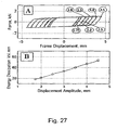
- the relationship between displacement amplitude of one of the at least two members and energy dissipation in the frictional joint is substantially linear. This makes the damper easier to model and thereby easier to design for a specific purpose.
- the bracing system can be arranged with the side plates being connected to one of the structural elements by means of two braces and the damper being arranged in a V-shaped bracing.
- this kind of bracing is referred to as being an invert-V bracing or a Chevron Bracing.
- the bracing system can be arranged with at least one of the side plates being connected to one of the structural elements by means of two braces and the damper being arranged in a D-shaped bracing, and similarly the bracing system can be arranged with at least one of the side plates being connected to one of the structural elements by means of two braces and the damper being arranged in a K-shaped bracing.
- the choice of arrangement may depend on the actual situation and will be selected by a professional designer.
- a further aspect of the invention relates to a damper for damping movements of large concrete panel walls in building structures, the device comprising:
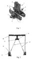
- the damper comprise a central plate and two side plates.
- plate 1 is the central plate and plates 4 are the side plates.
- the vertical plate pivotally connects the damper device to the girder of a frame structure through a hinge.
- the hinge is best seen in Fig. 1 and has numeral 8.
- the hinge is adapted in order not to introduce moment in the girder. This is essential e.g. when the damper is being retrofitted in buildings designed without the damper. Additionally the hinge increases the amount of relative rotation between the central plate and the side plates, which again increases the amount of energy dissipated in the system.
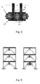
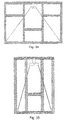
- the two side plates 4 connect the damper to a bracing system such as a Chevron bracing - as seen in Fig 2 - or similar arrangement of braces e.g. in a D shape or a K shape.
- a bracing system such as a Chevron bracing - as seen in Fig 2 - or similar arrangement of braces e.g. in a D shape or a K shape.
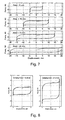
- Various bracing systems are shown in Fig. 4.
- the bracing system could comprise bars 13 being pretensioned in order to prevent them from buckling from compression force but could also comprise structural members capable of absorbing compression.
- the braces are preferably pivotally connected at both ends 14 and 15, by having plain bearings to the damper 16 and to the column base connection 17, as shown in Fig. 2. 18 is the upper frame column.
- All plates and the frictional pads have a centred hole for assembly with a bolt 2 with a nut 5 or similar kind of confining hinge pin.
- the bolt or similar hinge pin compresses the three plates 1 and 4 of the damper and the frictional pads 4 in a hinge like connection.
- the bolt 2 is used to control the normal force applied on the friction pad discs and the steel plates, whereby the damping characteristics of the damper is being changed.
- a spring 6 is preferably mounted between the bolt head and the side plate, between the nut and the side plate or at both sides.
- the spring could be of any kind but in a preferred embodiment of the invention a combination of discs springs 6 and washers 7, such as Belleville Washers, are used. These springs are initially cone shaped annular disc springs that flatten under compression. The washers are placed in order to prevent any marks on the steel plates due to the disc springs when they are in compression
- the damper is based on a very simple design and comprises only parts that are easily produced. At the same time it is easy to assemble and very flexible in arrangement. As seen in Fig. 4 and Fig 6 it can be arranged both in different configurations as well as in different types of bracing systems.
- the experimental program included two phases:
- the damper specimens described above, was placed within an Instron hydraulic testing machine type 8502.
- the actuator of this machine is capable of applying 250 kN dynamic load. Both displacement, forcing frequency or applied force control were possible through a controller unit.
- the test control was done from the PC running Instron software; "Max 5.2". All testing was done under displacement and forcing frequency control and all the resulting data transferred to Data Acquisition Board System which is integrated with system controller and in conjunction with a PC.
- the damper fixed to the Instron machine by a frame holder designed especially for this case, the frame being connected rigidly to the machine.
- the damper connected to this holder by two small plates fixed rigidly to the holder. Each of these plates connected to side plates by a hinge. These two plates were used later to connect the bracing bars to the damper. Inside these plates, a ball bearing was fixed in order to reduce friction through the damper activity with scaled frame model.
- the applied load was measured by a dynamometer having two strain gages fixed on it. This dynamometer was connected by a bearing hinge at both ends to prevent any kind of bending.
- the clamping force in the bolt was measured using two strain gages embedded inside the bolt.
- the required clamping force can be applied by tighten the bolt head with a spanner and getting the reading directly from a multimeter.
- the performance of the friction damper is, in general, affected by certain parameters. These parameters were studied in tests, which are:
- Brass is cheap and widely available commercial material. It's been used for long time for their known behaviour. Popove, 1993 had suggested to use them for their good and stable performance instead of steel, in his damper. In this work brass was chosen because steel and brass are known that they have a good combination in friction and for economic reasons.
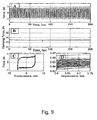
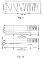
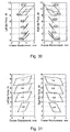
- Fig. 7 shows the applied displacement and resulting hysteresis loops. It's clearly shown that the amount of the area increased with the increase of the displacement and the friction force was almost constant without showing any fluctuation or disturbances. The higher forces that can be observed at the end of each cycle is because the relative velocity of the plates reach its minimum value.
- Test results shows that the amount of change in friction resistance was not much, at the end of 60 cycles, indicating that the initial bolt tension was still effective.
- the bolt connections emitted a roaring noise or chatter vibration from faying surfaces.
- the load level were not affected much by the presence of these vibratory noise & after approximately twenty cycles, the noise in the faying surfaces emitted a stable rubbing sound similar to metal milling work.
- the force was increased from 0.76 kN to 0.98 kN. This increase is probably due to many interacting phenomena:
- the friction damper with use of brass can be judged as having sufficient durability under practical condition.
- This material is coated with abrasives, which have a trade name called Felxovit, used to grain steel.
- This material is a fibre disc of 0,3 mm. thickness. It was glued on discs in order to have the required thickness in the damper.
- the thickness of the connected plates is changing upon cyclic loading. It increase due to temperature rise because of the generated heat caused by friction. On the other hand, wear at the contact surface will reduce the thickness.
- the device can develop such a variable reaction, it can be used as part of a motion control scheme as semi-active device.
- the friction damper can work under wide range of displacement amplitudes with constant and stable frictional forces.
- the 'frame holder' which was designed to hold the damper through the tests, was not rigid enough to prevent the small horizontal motion of the top part which caused by cyclic motion when large forces been used.
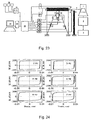
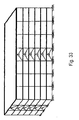
- the overall dimensions of the model frame are 1.125 m. height and 1.10m span.
- the frame can be seen in Fig 21.
- the frame structure columns are steel stripes of 50x15 mm.
- the beam is a hallow rectangular steel section of 90x50x5 mm and rigidly connected to the column by all around butt welding.
- the structure is fixed rigidly to the massive floor of the laboratory.
- the ratio of beam moment of inertia (lb) to column moment of inertia (Icol) is 91.73 in order to assure very rigid beam.
- This frame model has the following properties
- the relative rotation between the steel plates was measured by a potentiometer, with a roller head, fixed on side plate. These measurements divided by the distance between the potentiometer head and the centre-line of side plate.
- the rotation of central plate was measured by another potentiometer, and the readings were divided by the distance between the head and the centre of the hinge that connect the damper to the frame girder.
- the frame was tested with different displacement amplitudes in order to verify its influence on the damper behavior.
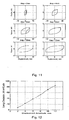
- the frame displacement was controlled with 1.75, 2, 2.5, 3, 3.5, 4 and 4.5 mm as shown in Fig. 27.
- the energy dissipation, which is the area of force - displacement curve, for each amplitude was, plotted verse frame displacement in Fig. 27.
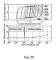
- bracing bars were pre-stressed with 1.02, 2.2, 4.4, 6.9, 8.8 and 10.1 kN respectively. From figure (11) its clearly seen that increasing pre-stressing force did not lead to decrease the frame displacements, especially with forces of 1.02 - 6.9 kN.
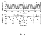
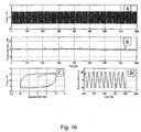
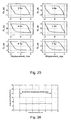
- Fig. 16 show time history test results of 3.0 Hz forcing frequency and excitation force of 0.8 kN.
- the frame response was very stable and constant, 20 B, and the relative rotation of the plates was also stable, Fig. 16 D. So the conclusion was after more than 100 cycle test that the damper performance was quite satisfactory.
Landscapes
- Engineering & Computer Science (AREA)
- Architecture (AREA)
- Emergency Management (AREA)
- Environmental & Geological Engineering (AREA)
- Business, Economics & Management (AREA)
- General Engineering & Computer Science (AREA)
- Structural Engineering (AREA)
- Civil Engineering (AREA)
- Mechanical Engineering (AREA)
- Physics & Mathematics (AREA)
- Aviation & Aerospace Engineering (AREA)
- Acoustics & Sound (AREA)
- Electromagnetism (AREA)
- Buildings Adapted To Withstand Abnormal External Influences (AREA)
- Vibration Prevention Devices (AREA)
- Rod-Shaped Construction Members (AREA)
- Vehicle Body Suspensions (AREA)
- Fluid-Damping Devices (AREA)
- Apparatus For Radiation Diagnosis (AREA)
- Wind Motors (AREA)
Abstract
Description
- clamping means for clamping at least two members together, so as to maintain a clamping force and friction between the at least two members in a joint,
- means for connecting each of the at least two members to respective ones of the structural elements,and
- The damper device can be mounted in 2 or more directions e.g. in a several storeys building.
- The damper device can be mounted in reinforced concrete frame structures with infill brick walls.
- The damper device can be mounted in large panel walls to reduce their sliding failure mechanism. The panels would typically be made from concrete but they may be made from other material such as timber, steel or composite materials.
- The damper device can be mounted in elevated water tanks to reduce their vibration response.
- The damper device can be mounted in bridges and elevated highways. It can be installed in two directions to reduce the response. As an example a number of dampers may be arrange in a first direction and a number of dampers may be arranged in a second direction. The dampers in the first direction may be provided with a damping structure, which is different from the damping structure of the dampers arranged in the second direction.
- The damper device can be used to reduce the vibration caused by elevated machines, which are mounted on a frame structure.
- The damper device can be mounted in many kinds of offshore structures to reduce their vibration response due to wave loads, e.g. from water or wind.
- The damper device can be mounted in ready-made garages.
- The damper device can be mounted in portable metal tents for damping the movements of the carrying columns and beams of the tent.
- The damper device can be used to reduce the rotation of joints in frame structures.
- The damper device can be mounted in several storeys industrial buildings.
- The damper device can be mounted in timber frame structures.
- The damper device can be mounted in metal towers.
- a bolt member with a bolt head,
- a nut with a nut head,
- at least two members being interconnected in a rotational joint for frictional damping of relative rotational movement between the at least two members,
- clamping means for clamping the at least two members together, so as to maintain a clamping force and friction between the at least two members in the rotational joint,
- means for connecting each of the at least two members to respective ones of the structural elements.
- at least one member interconnected to at least one panel in a first rotational joint,
- the at least one member being further connected to another panel or similar part of the building structure in a second rotational joint,
- one or both of the first or the second rotational joints providing a frictional damping of relative movement between the at least one member and the panel or similar building structure,
- one or both of the first or the second rotational joints further providing a sliding movement of the at least one member in relation to the panel or similar building structure to which it is attached, the sliding being enabled by means of a tolerance allowing movement in two perpendicular directions.
- clamping means for clamping the at least one member together with the panel or similar building structure, so as to maintain a clamping force and friction between the at least one member and the panel or similar building structure in the rotational joint.
The higher forces that can be observed at the end of each cycle is because the relative velocity of the plates reach its minimum value.
The force was increased from 0.76 kN to 0.98 kN. This increase is probably due to many interacting phenomena:
It's a composite material.
- FPM tests showed negligible damage to their friction surface.

- Forcing frequency.
- Displacement amplitude.
- Clamping force in damper.
- Forcing amplitude.
- Prestressing forces in bracing bars.
Claims (32)
- A device for damping movements of structural and non structural elements in civil engineering structures, the device comprising:characterised in that the at least two members are interconnected in a rotational joint for frictional damping of relative rotational movement between the at least two members (1,4), the two members being capable of rotationally moving in opposite directions,clamping means (2,5) for clamping at least two members (1,4) together, so as to maintain a clamping force and friction between the at least two members (1,4) in a joint,means for connecting each of the at least two members (1,4) to respective ones of the structural elements,and
- A device according to claim 1, further comprising a frictional pad (3) arranged between the at least two members (1,4) so as to establish contact between the at least two members and the frictional pad (3) so that the relative rotational movement of the at least two members is dampened by friction.
- A device according to claim 1 or 2, wherein the clamping means (2,5) are adapted to vary the clamping force.
- A device according to any one of claims 1 to 3, wherein the joint comprises a pin (2) extending through each of the at least two members (1,4).
- A device according to claim 4, comprising a bolt (2), at least a portion of the bolt (2) constituting the pin, the bolt having:the clamping force being determined by the pretension of the bolt.a bolt member (2) with a bolt head,a nut (5) with a nut head for engaging the bolt member (2),
- A device according to claim 5, further comprising means for maintaining a substantially temporally constant clamping force (6,7).
- A device according to claim 6, wherein the means for maintaining a substantially constant clamping force comprise at least one spring (6) arranged between the bolt head and a surface of one of the members (1,4) and/or between the nut head and a surface of one of the members (1,4).
- A device according to claim 7, wherein the spring comprises a disc spring (6).
- A device according to claim 8, comprising at least two disc springs (6).
- A device according to claim 9, wherein at least one disc spring (6) is arranged between the bolt head and a surface of one of the members (1,4), and wherein at least one disc spring (6) is arranged between the nut head and a surface of another one of the members (1,4).
- A device according to any one of claims 6 to 10, wherein the means for maintaining a substantially constant clamping force comprise hydraulic, pneumatic and/or electric means for maintaining the clamping force.
- A device according to any one of the preceding claims, wherein the at least two members comprise: a side plate (4) and a central plate (1) extending in substantially parallel planes.
- A device according to claim 12, wherein the frictional pad (3) is arranged between the side plate (4) and the central plate (1).
- A device according to claim 12, and comprising two side plates (4) arranged symmetrically around the central plate (1).
- A device according to claim 14, comprising two frictional pads (3), each frictional pad being arranged between a respective one of the side plates (4) and the central plate (1).
- A device according to any one of claims 12 to 15, wherein the central plate (1) is adapted to be connected to one of the structural elements (17,18) in a pivotal manner, so as to allow relative rotational movement between the central plate (1) and the structural element (17).
- A device according to any one of claims 12 to 15, wherein the central plate (1) is adapted to be connected to one of the structural elements (17,18) in a fixed manner, so as to prevent relative movement between the central plate (1) and the structural element (17).
- A device according to any one of claims 12 to 17, wherein the side plates (4) are adapted to be connected to one of the structural elements (17,18) in a pivotal manner, so as to allow relative rotational movement between the side plates (4) and the structural element (17).
- A device according to any one of claims 12 to 17, wherein the side plates (4) are adapted to be connected to one of the structural elements (17,18) in a fixed manner, so as to prevent relative movement between the side plates (4) and the structural element (17).
- A device according to any one of claims 1 to 19, wherein the friction pad material (3) comprises an asbestos free friction material.
- A device according to any one of claims 1 to 20, wherein the at least two members (1,4) are made of steel, anti-corrosive steel, brass, aluminium or any alloys comprising aluminium or any other steel material or composite of steel and plastics or composites of plastics and fibres of glass, carbon, kevlar or similar or composites of any ceramics materials and fibres of glass, carbon, kevlar or similar.
- A device according to any one of claims 1 to 20, wherein the clamping force shows a variation of less than 5% in a 400 cycle test with 0,5 Hz± 0,1 Hz forcing excitement frequency and an displacement amplitude of one of the at least two members of up to 10 mm at an applied excitement force of ± 2.5 kN and an initial clamping force of 4 kN±0,5kN.
- A device according to any one of claims 1 to 22, wherein the frictional moment in the frictional joint of the device shows a forcing frequency dependent variation of less than 5% in the range 2-7 Hz at a nominal frictional moment of 200 Nm±20Nm in 30-cycle tests at each frequency.
- A device according to any one of claims 1 to 23, having a substantially linear relationship between displacement amplitude of one of the at least two members and energy dissipation in the frictional joint.
- A bracing system for a building structure comprising at least two structural elements (17, 18) and a device for damping relative movements between the at least two structural elements according to claim 1.
- A bracing system according to claim 25, wherein the device for damping comprises the features of the damper according to any of claims 2 to 24.
- A bracing system according to claim 26, wherein the device for damping comprises at least two side plates (4) which are interconnected at at least one of their ends by means of an interconnecting element, and wherein a brace (13) is mounted to the interconnecting element.
- A bracing system according to claim 26 or 27, wherein at least one of the side plates (4) is connected to one of the structural elements (17,18) by means of a brace (13), and wherein the central plate (1) is connected or mounted to another one of the structural elements (18).
- A bracing system according to any one of claims 26 to 28, wherein at least one of the side plates (4) is connected to one of the structural elements (17,18) by means of two braces (13), the two braces (13) being connected to opposite ends of the side plate(s) (15), and wherein the central plate (1) is connected or mounted to another one of the structural elements (18).
- A bracing system according to any one of claims 26 to 28, wherein at least one of the side plates (4) is connected to one of the structural elements (17,18) by means of two braces (13) and the damper being arranged in a V-shaped bracing.
- A bracing system according to any one of claims 26 to 28, wherein at least one of the side plates (4) is connected to one of the structural elements (17,18) by means of two braces (13) and the damper being arranged in a D-shaped bracing.
- A bracing system according to any one of claims 26 to 28, wherein at least one of the side plates (4) is connected to one of the structural elements (17,18) by means of two braces (13) and the damper being arranged in a K-shaped bracing.
Priority Applications (1)
| Application Number | Priority Date | Filing Date | Title |
|---|---|---|---|
| EP05008468A EP1589166A1 (en) | 1999-08-03 | 2000-08-03 | A device for damping movements of structural elements and a bracing system |
Applications Claiming Priority (5)
| Application Number | Priority Date | Filing Date | Title |
|---|---|---|---|
| DKPA199901087 | 1999-08-03 | ||
| DK108799 | 1999-08-03 | ||
| US14738099P | 1999-08-06 | 1999-08-06 | |
| US147380P | 1999-08-06 | ||
| PCT/DK2000/000433 WO2001009466A1 (en) | 1999-08-03 | 2000-08-03 | A device for damping movements of structural elements and a bracing system |
Related Child Applications (1)
| Application Number | Title | Priority Date | Filing Date |
|---|---|---|---|
| EP05008468A Division EP1589166A1 (en) | 1999-08-03 | 2000-08-03 | A device for damping movements of structural elements and a bracing system |
Publications (2)
| Publication Number | Publication Date |
|---|---|
| EP1206615A1 EP1206615A1 (en) | 2002-05-22 |
| EP1206615B1 true EP1206615B1 (en) | 2005-04-20 |
Family
ID=26065205
Family Applications (1)
| Application Number | Title | Priority Date | Filing Date |
|---|---|---|---|
| EP00951267A Expired - Lifetime EP1206615B1 (en) | 1999-08-03 | 2000-08-03 | A device for damping movements of structural elements and a bracing system |
Country Status (14)
| Country | Link |
|---|---|
| EP (1) | EP1206615B1 (en) |
| JP (2) | JP2003506597A (en) |
| KR (1) | KR100853564B1 (en) |
| CN (1) | CN100379934C (en) |
| AT (1) | ATE293733T1 (en) |
| AU (1) | AU6426300A (en) |
| CA (1) | CA2380887C (en) |
| DE (1) | DE60019615D1 (en) |
| ES (1) | ES2241634T3 (en) |
| HK (1) | HK1046943A1 (en) |
| MX (1) | MXPA02001184A (en) |
| NZ (1) | NZ517405A (en) |
| TR (1) | TR200200866T2 (en) |
| WO (1) | WO2001009466A1 (en) |
Families Citing this family (27)
| Publication number | Priority date | Publication date | Assignee | Title |
|---|---|---|---|---|
| CN100338318C (en) | 2001-05-09 | 2007-09-19 | 减振技术公司 | Frictional damper for damping movement of structures |
| US6681538B1 (en) * | 2002-07-22 | 2004-01-27 | Skidmore, Owings & Merrill Llp | Seismic structural device |
| JP2009185566A (en) * | 2008-02-08 | 2009-08-20 | Sugimoto Kenchiku Kenkyusho:Kk | Vibration control structure and vibration control panel |
| JP2009210048A (en) * | 2008-03-05 | 2009-09-17 | Akebono Brake Ind Co Ltd | Friction damper |
| TR201911335T4 (en) * | 2008-03-14 | 2019-08-21 | Damptech As | Bearing for structures. |
| KR100952086B1 (en) * | 2009-07-06 | 2010-04-13 | 주식회사 에이브이티 | Apparatus for reducing earthquake vibration |
| JP5579415B2 (en) * | 2009-10-02 | 2014-08-27 | ダンプテック アー/エス | Vibration control structure |
| CN102782227B (en) * | 2009-10-02 | 2014-11-26 | 减振技术公司 | Damping system |
| KR101024538B1 (en) | 2010-12-14 | 2011-03-23 | 디에이치엔지니어링 주식회사 | Linear and rotary friction dampers, seismic reinforcement device using the same |
| JP5659090B2 (en) * | 2011-06-15 | 2015-01-28 | 国立大学法人埼玉大学 | Displacement suppression device |
| JP5960812B2 (en) * | 2011-07-15 | 2016-08-02 | ダンプテック アー/エスDamptech A/S | Passive damper |
| TR201607751A2 (en) * | 2016-06-08 | 2017-12-21 | Ali Salem Milani | Torsional Hysteretic Dumper |
| CN108049687B (en) * | 2017-05-17 | 2019-12-13 | 大连大学 | Self-resetting buckling restrained brace self-resetting method |
| CN108643667B (en) * | 2018-03-24 | 2020-10-13 | 北京工业大学 | Assembled composite energy-consuming steel beam-column structure capable of multistage vibration reduction and secondary displacement amplification |
| CN108824922A (en) * | 2018-08-09 | 2018-11-16 | 江苏蓝科减震科技有限公司 | A kind of friction damper |
| CN109537971A (en) * | 2018-12-28 | 2019-03-29 | 北京筑信润捷科技发展有限公司 | A kind of friction energy-dissipating damper |
| CN109914635A (en) * | 2019-04-10 | 2019-06-21 | 重庆大学 | A rotating frictional energy dissipation wall |
| US11396746B2 (en) | 2019-06-14 | 2022-07-26 | Quaketek Inc. | Beam coupler operating as a seismic brake, seismic energy dissipation device and seismic damage control device |
| KR102340824B1 (en) * | 2020-02-06 | 2021-12-17 | 경북대학교 산학협력단 | Friction Damper Including Bolt Tension Supplement Member and Management System Thereof |
| WO2021161293A1 (en) * | 2020-02-16 | 2021-08-19 | Teymour Honarbakhsh | Friction damper for a building structure |
| CN112459258A (en) * | 2020-11-05 | 2021-03-09 | 四川省振控科技有限公司 | Combined three-dimensional shock insulation support |
| CN112482600B (en) * | 2020-11-19 | 2023-07-04 | 东北林业大学 | A Composite Damper for Strengthening Building Frames |
| CN112879476B (en) * | 2021-01-04 | 2023-03-17 | 山东电力工程咨询院有限公司 | Chimney hangs passive frequency modulation damping vibration attenuation of inner tube and ends and shake device and chimney |
| CN112729752B (en) * | 2021-01-26 | 2022-08-02 | 中国空气动力研究与发展中心超高速空气动力研究所 | Spaceflight friction resistance sensor based on K-shaped pipe differential pressure measurement |
| CN114400597B (en) * | 2022-01-21 | 2024-04-05 | 福建成田科技有限公司 | High-strength mould pressing bridge frame |
| CN114593902B (en) * | 2022-03-04 | 2025-01-24 | 西安热工研究院有限公司 | An automatic detection system for nuclear power plant dampers based on big data |
| CN114737811A (en) * | 2022-04-21 | 2022-07-12 | 西安建筑科技大学 | Continuous plate suspended ceiling structure with rotary friction energy dissipation type inclined strut and installation method |
Family Cites Families (10)
| Publication number | Priority date | Publication date | Assignee | Title |
|---|---|---|---|---|
| US3418768A (en) | 1966-07-21 | 1968-12-31 | Cardan Bernhard | Building construction |
| US4409765A (en) | 1980-06-24 | 1983-10-18 | Pall Avtar S | Earth-quake proof building construction |
| US4910929A (en) * | 1986-08-20 | 1990-03-27 | Scholl Roger E | Added damping and stiffness elements |
| JP2602440B2 (en) * | 1988-01-06 | 1997-04-23 | 株式会社竹中工務店 | Vertical seismic isolation device |
| JP2717143B2 (en) * | 1988-06-20 | 1998-02-18 | 清水建設株式会社 | Vibration control method of buildings by friction |
| CN1017737B (en) * | 1990-08-02 | 1992-08-05 | 魏庆礼 | Frictional energy consumption type antiseismic structure |
| US5502932A (en) * | 1992-02-05 | 1996-04-02 | Chinese Building Technology Services Corporation Limited | Method and device of earthquake resistant & energy reduction for high-rise structures |
| JP3530301B2 (en) | 1996-03-22 | 2004-05-24 | 三菱重工業株式会社 | Lever type frictional resistance variable device |
| JPH10280660A (en) * | 1997-04-08 | 1998-10-20 | Fujita Corp | Base isolation device and friction damper for base isolation device |
| US6233884B1 (en) * | 1997-10-20 | 2001-05-22 | Steven B. Tipping | Method and apparatus to control seismic forces, accelerations, and displacements of structures |
-
2000
- 2000-08-03 DE DE60019615T patent/DE60019615D1/en not_active Expired - Lifetime
- 2000-08-03 AT AT00951267T patent/ATE293733T1/en not_active IP Right Cessation
- 2000-08-03 MX MXPA02001184A patent/MXPA02001184A/en active IP Right Grant
- 2000-08-03 JP JP2001513714A patent/JP2003506597A/en not_active Withdrawn
- 2000-08-03 AU AU64263/00A patent/AU6426300A/en not_active Abandoned
- 2000-08-03 CN CNB008125643A patent/CN100379934C/en not_active Expired - Lifetime
- 2000-08-03 CA CA002380887A patent/CA2380887C/en not_active Expired - Lifetime
- 2000-08-03 EP EP00951267A patent/EP1206615B1/en not_active Expired - Lifetime
- 2000-08-03 ES ES00951267T patent/ES2241634T3/en not_active Expired - Lifetime
- 2000-08-03 NZ NZ517405A patent/NZ517405A/en not_active IP Right Cessation
- 2000-08-03 WO PCT/DK2000/000433 patent/WO2001009466A1/en active IP Right Grant
- 2000-08-03 KR KR1020027001505A patent/KR100853564B1/en active IP Right Grant
- 2000-08-03 TR TR2002/00866T patent/TR200200866T2/en unknown
-
2002
- 2002-11-14 HK HK02108245.4A patent/HK1046943A1/en unknown
-
2005
- 2005-11-15 JP JP2005330518A patent/JP3898732B2/en not_active Expired - Lifetime
Also Published As
| Publication number | Publication date |
|---|---|
| CA2380887C (en) | 2009-07-07 |
| JP3898732B2 (en) | 2007-03-28 |
| TR200200866T2 (en) | 2002-10-21 |
| CN1373827A (en) | 2002-10-09 |
| CN100379934C (en) | 2008-04-09 |
| MXPA02001184A (en) | 2004-05-21 |
| DE60019615D1 (en) | 2005-05-25 |
| HK1046943A1 (en) | 2003-01-30 |
| KR20020033753A (en) | 2002-05-07 |
| KR100853564B1 (en) | 2008-08-22 |
| EP1206615A1 (en) | 2002-05-22 |
| ATE293733T1 (en) | 2005-05-15 |
| ES2241634T3 (en) | 2005-11-01 |
| JP2003506597A (en) | 2003-02-18 |
| JP2006125189A (en) | 2006-05-18 |
| NZ517405A (en) | 2003-01-31 |
| AU6426300A (en) | 2001-02-19 |
| WO2001009466A1 (en) | 2001-02-08 |
| CA2380887A1 (en) | 2001-02-08 |
Similar Documents
| Publication | Publication Date | Title |
|---|---|---|
| EP1206615B1 (en) | A device for damping movements of structural elements and a bracing system | |
| US6840016B1 (en) | Device for damping movements of structural elements and a bracing system | |
| EP1390587B1 (en) | Frictional damper for damping movement of structures | |
| US20050115170A1 (en) | Device for damping movements of structural elements and a bracing system | |
| JP4139901B2 (en) | Damping structure of wooden building and damping method of wooden building | |
| Mualla | Parameters influencing the behavior of a new friction damper device | |
| Mualla | Experimental evaluation of new friction damper device | |
| Mualla et al. | Enhanced response through supplementary friction damper devices | |
| JP3389521B2 (en) | Vibration energy absorber for tension structure and its construction method | |
| US6256943B1 (en) | Antiseismic device for buildings and works of art | |
| EP1589166A1 (en) | A device for damping movements of structural elements and a bracing system | |
| Rao et al. | Experimental study of base-isolated structures | |
| Mualla et al. | Numerical predictions of shaking table tests on a full scale friction-damped structure | |
| JPH1082203A (en) | Vibration damper for building | |
| Peralta et al. | Seismic performance of rehabilitated wood diaphragms | |
| Ribakov et al. | Experimental methods for selecting base isolation parameters for public buildings | |
| KR101291009B1 (en) | Jig device for testing damper brace | |
| Agrawal | Enhanced response through supplementary friction damper devices | |
| SE521850C2 (en) | Floors | |
| Martinelli et al. | Behaviour of Steel Structures in Seismic Areas, Mazzolani & Tremblay (eds) & 2000 Balkema, Rotterdam, ISBN 90 5809 130 9 Seismic design and response of a 14-story concentrically braced steel building | |
| Wetzel | Friction Bearing Device to Limit Service Level Damage of Lightweight Structures | |
| Zwerneman et al. | Fatigue in Steel Highway Bridges under Random Loading | |
| Agerskov et al. | Closure to “Fatigue in Steel Highway Bridges under Random Loading” by Henning Agerskov and Jette Andkjær Nielsen |
Legal Events
| Date | Code | Title | Description |
|---|---|---|---|
| PUAI | Public reference made under article 153(3) epc to a published international application that has entered the european phase |
Free format text: ORIGINAL CODE: 0009012 |
|
| 17P | Request for examination filed |
Effective date: 20020304 |
|
| AX | Request for extension of the european patent |
Free format text: AL PAYMENT 20020304;LT PAYMENT 20020304;LV PAYMENT 20020304;MK PAYMENT 20020304;RO PAYMENT 20020304;SI PAYMENT 20020304 |
|
| 17Q | First examination report despatched |
Effective date: 20030523 |
|
| GRAP | Despatch of communication of intention to grant a patent |
Free format text: ORIGINAL CODE: EPIDOSNIGR1 |
|
| GRAS | Grant fee paid |
Free format text: ORIGINAL CODE: EPIDOSNIGR3 |
|
| GRAA | (expected) grant |
Free format text: ORIGINAL CODE: 0009210 |
|
| AK | Designated contracting states |
Kind code of ref document: B1 Designated state(s): AT BE CH CY DE DK ES FI FR GB GR IE IT LI LU MC NL PT SE |
|
| AX | Request for extension of the european patent |
Extension state: AL LT LV MK RO SI |
|
| PG25 | Lapsed in a contracting state [announced via postgrant information from national office to epo] |
Ref country code: BE Free format text: LAPSE BECAUSE OF FAILURE TO SUBMIT A TRANSLATION OF THE DESCRIPTION OR TO PAY THE FEE WITHIN THE PRESCRIBED TIME-LIMIT Effective date: 20050420 Ref country code: LI Free format text: LAPSE BECAUSE OF FAILURE TO SUBMIT A TRANSLATION OF THE DESCRIPTION OR TO PAY THE FEE WITHIN THE PRESCRIBED TIME-LIMIT Effective date: 20050420 Ref country code: CH Free format text: LAPSE BECAUSE OF FAILURE TO SUBMIT A TRANSLATION OF THE DESCRIPTION OR TO PAY THE FEE WITHIN THE PRESCRIBED TIME-LIMIT Effective date: 20050420 Ref country code: NL Free format text: LAPSE BECAUSE OF FAILURE TO SUBMIT A TRANSLATION OF THE DESCRIPTION OR TO PAY THE FEE WITHIN THE PRESCRIBED TIME-LIMIT Effective date: 20050420 Ref country code: FI Free format text: LAPSE BECAUSE OF FAILURE TO SUBMIT A TRANSLATION OF THE DESCRIPTION OR TO PAY THE FEE WITHIN THE PRESCRIBED TIME-LIMIT Effective date: 20050420 Ref country code: AT Free format text: LAPSE BECAUSE OF FAILURE TO SUBMIT A TRANSLATION OF THE DESCRIPTION OR TO PAY THE FEE WITHIN THE PRESCRIBED TIME-LIMIT Effective date: 20050420 |
|
| REG | Reference to a national code |
Ref country code: GB Ref legal event code: FG4D |
|
| REG | Reference to a national code |
Ref country code: CH Ref legal event code: EP |
|
| REG | Reference to a national code |
Ref country code: IE Ref legal event code: FG4D |
|
| REF | Corresponds to: |
Ref document number: 60019615 Country of ref document: DE Date of ref document: 20050525 Kind code of ref document: P |
|
| PG25 | Lapsed in a contracting state [announced via postgrant information from national office to epo] |
Ref country code: SE Free format text: LAPSE BECAUSE OF FAILURE TO SUBMIT A TRANSLATION OF THE DESCRIPTION OR TO PAY THE FEE WITHIN THE PRESCRIBED TIME-LIMIT Effective date: 20050720 Ref country code: DK Free format text: LAPSE BECAUSE OF FAILURE TO SUBMIT A TRANSLATION OF THE DESCRIPTION OR TO PAY THE FEE WITHIN THE PRESCRIBED TIME-LIMIT Effective date: 20050720 |
|
| PG25 | Lapsed in a contracting state [announced via postgrant information from national office to epo] |
Ref country code: DE Free format text: LAPSE BECAUSE OF FAILURE TO SUBMIT A TRANSLATION OF THE DESCRIPTION OR TO PAY THE FEE WITHIN THE PRESCRIBED TIME-LIMIT Effective date: 20050721 |
|
| PG25 | Lapsed in a contracting state [announced via postgrant information from national office to epo] |
Ref country code: CY Free format text: LAPSE BECAUSE OF FAILURE TO SUBMIT A TRANSLATION OF THE DESCRIPTION OR TO PAY THE FEE WITHIN THE PRESCRIBED TIME-LIMIT Effective date: 20050803 Ref country code: IE Free format text: LAPSE BECAUSE OF NON-PAYMENT OF DUE FEES Effective date: 20050803 Ref country code: LU Free format text: LAPSE BECAUSE OF NON-PAYMENT OF DUE FEES Effective date: 20050803 Ref country code: GB Free format text: LAPSE BECAUSE OF NON-PAYMENT OF DUE FEES Effective date: 20050803 |
|
| PG25 | Lapsed in a contracting state [announced via postgrant information from national office to epo] |
Ref country code: MC Free format text: LAPSE BECAUSE OF NON-PAYMENT OF DUE FEES Effective date: 20050831 |
|
| REG | Reference to a national code |
Ref country code: GR Ref legal event code: EP Ref document number: 20050402221 Country of ref document: GR |
|
| PG25 | Lapsed in a contracting state [announced via postgrant information from national office to epo] |
Ref country code: PT Free format text: LAPSE BECAUSE OF FAILURE TO SUBMIT A TRANSLATION OF THE DESCRIPTION OR TO PAY THE FEE WITHIN THE PRESCRIBED TIME-LIMIT Effective date: 20050920 |
|
| LTIE | Lt: invalidation of european patent or patent extension |
Effective date: 20050420 |
|
| REG | Reference to a national code |
Ref country code: CH Ref legal event code: PL |
|
| NLV1 | Nl: lapsed or annulled due to failure to fulfill the requirements of art. 29p and 29m of the patents act | ||
| REG | Reference to a national code |
Ref country code: ES Ref legal event code: FG2A Ref document number: 2241634 Country of ref document: ES Kind code of ref document: T3 |
|
| PLBE | No opposition filed within time limit |
Free format text: ORIGINAL CODE: 0009261 |
|
| STAA | Information on the status of an ep patent application or granted ep patent |
Free format text: STATUS: NO OPPOSITION FILED WITHIN TIME LIMIT |
|
| 26N | No opposition filed |
Effective date: 20060123 |
|
| GBPC | Gb: european patent ceased through non-payment of renewal fee |
Effective date: 20050803 |
|
| REG | Reference to a national code |
Ref country code: IE Ref legal event code: MM4A |
|
| EN | Fr: translation not filed | ||
| PG25 | Lapsed in a contracting state [announced via postgrant information from national office to epo] |
Ref country code: FR Free format text: LAPSE BECAUSE OF NON-PAYMENT OF DUE FEES Effective date: 20050831 |
|
| PG25 | Lapsed in a contracting state [announced via postgrant information from national office to epo] |
Ref country code: FR Free format text: LAPSE BECAUSE OF NON-PAYMENT OF DUE FEES Effective date: 20050420 |
|
| REG | Reference to a national code |
Ref country code: HK Ref legal event code: WD Ref document number: 1046943 Country of ref document: HK |
|
| PGFP | Annual fee paid to national office [announced via postgrant information from national office to epo] |
Ref country code: IT Payment date: 20190822 Year of fee payment: 20 |
|
| PGFP | Annual fee paid to national office [announced via postgrant information from national office to epo] |
Ref country code: GR Payment date: 20190828 Year of fee payment: 20 |
|
| PGFP | Annual fee paid to national office [announced via postgrant information from national office to epo] |
Ref country code: ES Payment date: 20191003 Year of fee payment: 20 |
|
| REG | Reference to a national code |
Ref country code: ES Ref legal event code: FD2A Effective date: 20201126 |
|
| PG25 | Lapsed in a contracting state [announced via postgrant information from national office to epo] |
Ref country code: ES Free format text: LAPSE BECAUSE OF EXPIRATION OF PROTECTION Effective date: 20200804 |