EP1206367B1 - Foldable u-shaped headrest - Google Patents
Foldable u-shaped headrest Download PDFInfo
- Publication number
- EP1206367B1 EP1206367B1 EP00950795A EP00950795A EP1206367B1 EP 1206367 B1 EP1206367 B1 EP 1206367B1 EP 00950795 A EP00950795 A EP 00950795A EP 00950795 A EP00950795 A EP 00950795A EP 1206367 B1 EP1206367 B1 EP 1206367B1
- Authority
- EP
- European Patent Office
- Prior art keywords
- headrest
- shaped headrest
- vehicle seat
- seat assembly
- base
- Prior art date
- Legal status (The legal status is an assumption and is not a legal conclusion. Google has not performed a legal analysis and makes no representation as to the accuracy of the status listed.)
- Expired - Lifetime
Links
- 239000000463 material Substances 0.000 claims description 10
- 230000000712 assembly Effects 0.000 description 3
- 238000000429 assembly Methods 0.000 description 3
- 238000004519 manufacturing process Methods 0.000 description 3
- 229910000639 Spring steel Inorganic materials 0.000 description 2
- 125000001475 halogen functional group Chemical group 0.000 description 2
- 238000004026 adhesive bonding Methods 0.000 description 1
- 230000001419 dependent effect Effects 0.000 description 1
- 230000001771 impaired effect Effects 0.000 description 1
- 238000009877 rendering Methods 0.000 description 1
Images



Classifications
-
- B—PERFORMING OPERATIONS; TRANSPORTING
- B60—VEHICLES IN GENERAL
- B60N—SEATS SPECIALLY ADAPTED FOR VEHICLES; VEHICLE PASSENGER ACCOMMODATION NOT OTHERWISE PROVIDED FOR
- B60N2/00—Seats specially adapted for vehicles; Arrangement or mounting of seats in vehicles
- B60N2/80—Head-rests
- B60N2/806—Head-rests movable or adjustable
- B60N2/838—Tiltable
- B60N2/856—Tiltable movable to an inoperative or stowed position
- B60N2/859—Tiltable movable to an inoperative or stowed position specially adapted for rear seats
-
- B—PERFORMING OPERATIONS; TRANSPORTING
- B60—VEHICLES IN GENERAL
- B60N—SEATS SPECIALLY ADAPTED FOR VEHICLES; VEHICLE PASSENGER ACCOMMODATION NOT OTHERWISE PROVIDED FOR
- B60N2/00—Seats specially adapted for vehicles; Arrangement or mounting of seats in vehicles
- B60N2/80—Head-rests
- B60N2/806—Head-rests movable or adjustable
- B60N2/838—Tiltable
- B60N2/841—Tiltable characterised by their locking devices
- B60N2/85—Tiltable characterised by their locking devices with continuous positioning
-
- B—PERFORMING OPERATIONS; TRANSPORTING
- B60—VEHICLES IN GENERAL
- B60N—SEATS SPECIALLY ADAPTED FOR VEHICLES; VEHICLE PASSENGER ACCOMMODATION NOT OTHERWISE PROVIDED FOR
- B60N2/00—Seats specially adapted for vehicles; Arrangement or mounting of seats in vehicles
- B60N2/80—Head-rests
- B60N2/806—Head-rests movable or adjustable
- B60N2/874—Head-rests movable or adjustable movable to an inoperative or stowed position
Definitions
- the present invention relates to a foldable halo style headrest in which opposing ends of a U-shaped headrest member are connected to opposing ends of a covered, non-pivotable base.
- Recent legislation has required vehicle seat headrests to extend higher in vehicles for improved safety.
- European legislation requires that the top of the headrest be positioned 750 mm above the hip pivot point, which is substantially higher than most current designs.
- the collapse of the seat is difficult due to interference caused by the extended height of the headrest.
- folding headrests have been developed to accommodate such designs and allow tumbling and dumping of tall seats.
- the folding headrest also maximizes visibility to the rear of the vehicle when folded, particularly through the rearview mirror, and is therefore a desirable feature, particularly when such folding also enables tumbling and dumping of taller seats.
- a vehicle seat assembly according to the preamble of claim 1 is known from US 5,531,505.
- a generally U-shaped cradle member is provided around the outer circumference of a standard headrest. In the usual seating position, this cradle member is flush with the headrest. If the passenger intends to rest or would otherwise prefer head support, the cradle member can be pivoted into a position in which the two legs of the U-shaped cradle member project from the headrest in a forward direction, thereby giving lateral support to the passenger's head.
- This vehicle seat assembly however, has the drawback that the cradle member enlarges the volume of the headrest, thereby further impairing visibility to the rear of the vehicle. Even in the forward projecting cradle position, the headrest assembly has a greater lateral width than standard headrests, such that visibility is still impaired.
- a central cushion in a generally U-shaped headrest may be slid downwards in order to provide better comfort to a passenger's head.
- the object of the present invention is to provide a vehicle seat assembly which is improved over the known vehicle seat assembly with respect to ease of handling, aesthetic appearance and visibility to the rear of the vehicle.
- the present invention overcomes the above-referenced shortcomings of prior art headrest assemblies by providing a U-shaped headrest having opposing ends which are pivotally connected to a covered, non-pivotable base.
- pivotal movement of the U-shaped headrest is allowed without requiring trenches in either the base or the U-shaped headrest.
- This design significantly reduces manufacturing costs over prior art designs.
- This design also allows folding and tumbling of the seat without removing the headrest.
- Detents are provided within the base for properly positioning the headrest, and the U-shaped headrest is positively locked in the upright position and actuated by a release button.
- the invention provides a vehicle seat assembly including a seat back with a support post vertically adjustable with respect to the seat back.
- a cushioned base is non-movably mounted to the support post and covered by a trim cover material.
- the base has first and second ends and a bottom surface facing the seat back.
- a U-shaped headrest has opposing ends pivotally connected to the first and second ends of the base, respectively.
- the U-shaped headrest is covered by a trim cover material, and is pivotally movable between an upright position for use and a horizontal position for seat tumbling, wherein the U-shaped headrest is substantially flush with the bottom surface when in the horizontal position.
- the base and the U-shaped headrest cooperate to form an opening therebetween for improved visibility when the U-shaped headrest is in the upright position.
- the base includes a cam engaged with the U-shaped headrest for selectively positioning the headrest in the upright or horizontal position.
- an automatic locking mechanism can be provided which automatically locks the U-shaped headrest in the upright position once the headrest is moved to the upright position.
- the locking mechanism includes a release button for unlocking.
- the present invention provides an improved foldable headrest assembly for a vehicle seat, wherein the assembly does not require trenches formed in the trim cover material for pivoting.
- the present invention may provide an improved headrest assembly for a vehicle seat which is foldable between upright and collapsed positions, and automatically locks in the upright position.
- FIG. 1 shows a vehicle seat assembly 10 in accordance with the present invention.
- the vehicle seat assembly 10 includes a lower seat 12 with a seat back 14 pivotally connected thereto. Headrest assemblies 16, 18, 20 are attached to the top of the seat back 14.
- the vehicle seat assembly 10 is configured for use as a rear seat in a vehicle, such as a minivan.
- a vehicle such as a minivan.
- the headrest assemblies 16, 18, 20 may be folded forward for improved rear visibility in the vehicle, and also to enable tumbling and dumping of the seat assembly 10 forward in the vehicle.
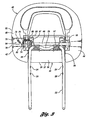
- a headrest assembly 16 includes a support post 22 which is vertically adjustable with respect to the seat back 14 by means of the notches 24,26 shown in Figure 3.
- the support post 26 is mounted within generally cylindrical receiving tubes (not shown) mounted in the top of the seat back 14.
- the support post 22 is accordingly non-pivotally mounted to the seat back 14, but vertically adjustable with respect to the seat back 14.
- the support post 22 forms a generally U-shaped configuration.
- the support post 22 is selectively removable from the seat back 14, thereby rendering the entire headrest assembly 16 removable.
- the base 34 and U-shaped headrest 40 cooperate to form an opening 33 there between for improved visibility when the U-shaped headrest 40 is in the upright position.
- the support post 22 includes an upper portion 28, which is covered by a cushion 30, and the cushion 30 is, in turn, covered by a trim cover material 32.
- the cushion 30 and trim cover material 32 cooperate to form a base 34 which includes a support portion 68.
- the base 34 is non-movably mounted to the support post 22.
- the base 34 includes first and second ends 36,38, respectively, and has a bottom surface 35 facing the seat back.
- a U-shaped headrest 40 has opposing ends 42,44 which are pivotally connected to the first and second ends 36, 38, respectively, of the base 34 along the pivot shaft 46.
- the U-shaped headrest also includes a cushion 48, and is covered by a trim cover material 50.
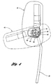
- the U-shaped headrest 40 is pivotally movable about the pivot shaft 46 between the upright position for use, and the horizontal position (shown in phantom in Figure 4) for seat tumbling, wherein the U-shaped headrest is substantially flush with the bottom surface 35 when in the horizontal position.
- the base 34 includes a spring steel cam 52 having a plurality of detents 58, 60, 62 engageable with a finger 54 of the U-shaped headrest 40.
- the finger 54 is integrally molded with a halo structure 41 of the U-shaped headrest 40.
- At least one return spring 56 which includes a coiled portion 57 wrapped around the upper portion 28 of the support post 22, pivotally biases the U-shaped headrest 40 toward the upright position shown in Figure 6. In this position, the finger 54 engages the first detent 58.
- the U-shaped headrest 40 is positively locked in the upright position by a mechanism to be described below.
- the U-shaped headrest 40 may be pivoted about the pivot shaft 46 against the bias of the return spring 56 to a position of engagement with the second detent 60, as illustrated in phantom in Figure 4. This position is particularly useful for folding and tumbling seats.
- a third detent 62 is optionally provided for a normal folding seat.
- an automatic locking mechanism 64 is provided for positively locking the U-shaped headrest 40 in the upright position. Once the U-shaped headrest 40 has been pivoted to the upright position, a lock pin 66 automatically engages a hole 67 formed through the support portion 68 of the base 34 to positively lock the headrest 40 in the upright position.
- the automatic locking mechanism 64 includes a spring 70 which pivotally biases a link 72 about a pivot point 74.
- the link 72 is connected to the lock pin 66 at one end. Accordingly, the bias of the spring 70 causes pivotal movement of the link 72 about the pivot point 74, which causes the lock pin 66 to automatically force itself into the hole 67 formed in the support portion 68 of the base, thereby positively locking the U-shaped headrest 40 in the upright position.
- a release button 76 is guided in a channel 78, and engages a first end 80 of the link 72 to cause selective pivotal movement of the link about the pivot point 74, thereby pulling the lock pin 66 away from the hole 67 formed in the support portion 68 of the base, thereby unlocking the headrest 40 for pivotal movement about the pivot shaft 46.
- the spring steel cam 52 may be formed as an over center spring which automatically biases the finger 54 toward opposing positions corresponding with the upright and collapsed positions of the U-shaped headrest 40.
Landscapes
- Engineering & Computer Science (AREA)
- Aviation & Aerospace Engineering (AREA)
- Transportation (AREA)
- Mechanical Engineering (AREA)
- Seats For Vehicles (AREA)
- Chair Legs, Seat Parts, And Backrests (AREA)
Description
Claims (7)
- A vehicle seat assembly (10) comprising a seat back (14); a support post (22) vertically adjustable with respect to the seat back (14); a base (34) having a cushion (30) and being non-movably mounted to the support post (22) and covered by a trim cover material (32), the base (34) having first (36) and second ends (38), and a U-shaped headrest (40) having opposing ends (42, 44) and being pivotally connected to the first (36) and second ends (38) of the base (34), respectively, the U-shaped headrest (40) covered by a trim cover material (50), characterized in that the base (34) and U-shaped headrest (40) cooperate to form an opening (33) therebetween for improved visibility when the U-shaped headrest (40) is in the upright position, wherein further the U-shaped headrest (40) is pivotally movable between an upright position for use and a horizontal position for seat tumbling, the U-shaped headrest (40) being pivotally movable to the horizontal position to reduce height of the vehicle seat assembly to improve rear visibility and to allow folding and tumbling of the vehicle seat assembly (10) without removing the U-shaped headrest (40).
- The vehicle seat assembly of claim 1, wherein the base (34) includes a cam (52) engaged with the U-shaped headrest (40) for selectively positioning the headrest (40) in the upright or horizontal position.
- The vehicle seat assembly of claim 2, further comprising a return spring (56) biasing the U-shaped headrest (40) toward the upright position.
- The vehicle seat assembly of claim 2, further comprising an automatic locking mechanism which automatically locks the U-shaped headrest (40) in the upright position once the headrest (40) is moved to the upright position, said locking mechanism including a release button (76) for unlocking.
- The vehicle seat assembly of claim 1, wherein the support post (22) is configured to be selectively removable from the seat back (14).
- The vehicle seat assembly of claim 1, wherein said support post (22) is non-pivotally mounted with respect to the seat back (14).
- A vehicle seat assembly according to any of the preceding claims, characterized by the base having a bottom surface (35) facing the seat back (14), and by the U-shaped headrest (40) being substantially flush with the bottom surface (35) when in the horizontal position.
Applications Claiming Priority (3)
| Application Number | Priority Date | Filing Date | Title |
|---|---|---|---|
| US09/368,872 US6129421A (en) | 1999-08-05 | 1999-08-05 | Foldable halo style headrest |
| US368872 | 1999-08-05 | ||
| PCT/US2000/020497 WO2001010669A1 (en) | 1999-08-05 | 2000-07-27 | Foldable u-shaped headrest |
Publications (2)
| Publication Number | Publication Date |
|---|---|
| EP1206367A1 EP1206367A1 (en) | 2002-05-22 |
| EP1206367B1 true EP1206367B1 (en) | 2005-11-23 |
Family
ID=23453114
Family Applications (1)
| Application Number | Title | Priority Date | Filing Date |
|---|---|---|---|
| EP00950795A Expired - Lifetime EP1206367B1 (en) | 1999-08-05 | 2000-07-27 | Foldable u-shaped headrest |
Country Status (4)
| Country | Link |
|---|---|
| US (1) | US6129421A (en) |
| EP (1) | EP1206367B1 (en) |
| DE (1) | DE60024274T2 (en) |
| WO (1) | WO2001010669A1 (en) |
Families Citing this family (58)
| Publication number | Priority date | Publication date | Assignee | Title |
|---|---|---|---|---|
| JP4411715B2 (en) * | 2000-01-28 | 2010-02-10 | アイシン精機株式会社 | Headrest device |
| FR2806983B1 (en) * | 2000-04-04 | 2002-09-27 | Cera | HEADREST, PARTICULARLY FOR A MOTOR VEHICLE SEAT |
| FR2814122B1 (en) * | 2000-09-20 | 2003-01-10 | Cera | MULTI-POSITION HEADREST AND SEAT WITH HEADREST |
| JP3676716B2 (en) * | 2001-10-05 | 2005-07-27 | 株式会社ホンダアクセス | Speaker mounting structure for vehicle headrest |
| US6779839B2 (en) | 2001-10-23 | 2004-08-24 | Lear Corporation | Flip head restraint |
| CA2418563A1 (en) | 2002-02-11 | 2003-08-11 | Intier Automotive Inc. | Head restraint pivot latch |
| US6767064B2 (en) * | 2002-02-27 | 2004-07-27 | Lear Corporation | Translatable head restraint for automotive seat backrest |
| FR2837150B1 (en) * | 2002-03-15 | 2004-09-10 | Faurecia Sieges Automobile | HEADREST FOR MOTOR VEHICLE SEAT AND SEATS PROVIDED WITH SUCH HEAD RESTRAINTS |
| US6893095B2 (en) | 2002-05-15 | 2005-05-17 | Daimlerchrysler Corporation | Horizontally pivoting headrest for motor vehicle |
| US6758527B2 (en) | 2002-05-15 | 2004-07-06 | Daimlerchrysler Corporation | Headrest retractable against motor vehicle headliner |
| US6616235B1 (en) | 2002-06-17 | 2003-09-09 | World Market, Inc. | Seat assembly with integral head/neck rest |
| US6962392B2 (en) | 2002-07-24 | 2005-11-08 | O'connor Richard W | Articulated headrest |
| JP2004082792A (en) * | 2002-08-23 | 2004-03-18 | Tachi S Co Ltd | Swing headrest frame assembly |
| US6910740B2 (en) * | 2002-12-09 | 2005-06-28 | Camaco | Articulated headrestraint system |
| DE10319453B3 (en) * | 2003-04-29 | 2004-06-24 | Faurecia Autositze Gmbh & Co. Kg | Forwards folding backrest for automobile passenger seat with headrest pivoted forwards upon release of spring tension in crash situation |
| WO2005012034A1 (en) | 2003-07-28 | 2005-02-10 | Intier Automotive Inc. | Tilting head restraint with a use position and a stowed position |
| US7575282B2 (en) * | 2004-03-10 | 2009-08-18 | Gill Industries, Inc. | Foldable head restraint |
| DE20313127U1 (en) * | 2003-08-22 | 2005-01-05 | Kendrion Rsl Gmbh & Co. Kg | Headrest for vehicles |
| US7237843B2 (en) * | 2004-01-15 | 2007-07-03 | Johnson Controls Technology Company | Folding head restraint |
| DE102004005590B4 (en) * | 2004-02-04 | 2008-10-23 | Schukra Gerätebau AG | Headrest assembly |
| JP4647331B2 (en) * | 2004-03-23 | 2011-03-09 | 株式会社東洋シート | Vehicle seat with headrest |
| EP1737699B1 (en) * | 2004-03-30 | 2009-05-27 | Wilhelm Karmann GmbH | Vehicle seat and cabriolet vehicle comprising one such seat |
| US7325877B2 (en) * | 2004-04-15 | 2008-02-05 | Windsor Machine & Stamping Limited | Foldable headrest assembly |
| US20050242640A1 (en) * | 2004-04-15 | 2005-11-03 | Barko Jerry S | Folding headrest assembly |
| WO2005120894A1 (en) * | 2004-06-09 | 2005-12-22 | Kongsberg Automotive Ab | A device for a collapsible headrest |
| FR2879141B1 (en) * | 2004-12-15 | 2007-03-30 | Renault Sas | RETRACTABLE HEADREST FOR MOTOR VEHICLE SEAT, AND CORRESPONDING SEAT. |
| US20090071283A1 (en) * | 2007-09-18 | 2009-03-19 | Lear Corporation | Selective remote head restraint actuation |
| US8152242B2 (en) * | 2005-04-04 | 2012-04-10 | Lear Corporation | Selective remote head restraint actuation |
| US7178874B2 (en) * | 2005-04-28 | 2007-02-20 | Pierce Manufacturing Company | Lateral head restraint system |
| US7559608B2 (en) * | 2005-09-14 | 2009-07-14 | Mazda Motor Corporation | Seat for vehicle |
| US7322646B2 (en) * | 2005-11-02 | 2008-01-29 | Lear Corporation | Folding head restraint mechanism |
| US20070132299A1 (en) * | 2005-12-14 | 2007-06-14 | Lear Corporation | Head restraint system and method for producing same |
| US7669932B1 (en) * | 2006-02-28 | 2010-03-02 | Grammer A.G. | Headrest |
| FR2901199B1 (en) * | 2006-05-19 | 2009-04-03 | Peugeot Citroen Automobiles Sa | SEAT BACKREST COMPRISING A ROTATING MOBILE HEADREST |
| WO2008096766A1 (en) * | 2007-02-05 | 2008-08-14 | Ts Tech Co., Ltd. | Headrest and vehicle seat with the headrest |
| JP5057823B2 (en) * | 2007-03-31 | 2012-10-24 | テイ・エス テック株式会社 | Headrest and vehicle seat provided with the headrest |
| JP5252824B2 (en) * | 2007-03-31 | 2013-07-31 | テイ・エス テック株式会社 | Headrest and vehicle seat provided with the headrest |
| JP2008272270A (en) * | 2007-04-28 | 2008-11-13 | Bizen Hatsujo Kk | Vehicle headrest |
| FR2916423B1 (en) * | 2007-05-23 | 2010-02-12 | Airbus | SEAT WITH PIVOTING HEADREST |
| JP4063863B1 (en) * | 2007-07-19 | 2008-03-19 | 備前発条株式会社 | Headrest |
| KR20090063580A (en) * | 2007-12-14 | 2009-06-18 | 현대자동차주식회사 | Headrest device of vehicle |
| US7758126B2 (en) * | 2008-01-10 | 2010-07-20 | Honda Motor Co., Ltd. | Folding headrest |
| DE102009045833A1 (en) * | 2009-10-20 | 2011-05-26 | Lear Corp., Southfield | Seat device with an adjustable headrest device |
| DE102010001598B3 (en) * | 2010-02-04 | 2011-07-28 | Lear Corp., Mich. | Seat assembly with a movable headrest assembly |
| US20110227387A1 (en) * | 2010-03-16 | 2011-09-22 | Michael Kolich | Occupant controlled multi-surface head restraint for improved comfort |
| US8511751B2 (en) * | 2010-04-19 | 2013-08-20 | Bae Industries, Inc. | Headrest exhibiting a widthwise bar engaging side sectors in combination with a strap engaging/lift feature for permitting forward and/or rearward dump |
| DE102010023967B4 (en) * | 2010-06-09 | 2018-04-26 | Adient Luxembourg Holding S.À R.L. | headrest |
| US8672410B2 (en) * | 2011-06-21 | 2014-03-18 | Tokai Chemical Industries, Ltd. | Tiltable headrest device |
| US20140312672A1 (en) * | 2013-03-15 | 2014-10-23 | Nathan A. Scolari | Adjustable Head Rest |
| US9731637B2 (en) | 2015-08-17 | 2017-08-15 | Lear Corporation | Seat assembly having a headrest and method of assembly |
| US10179433B2 (en) * | 2017-03-02 | 2019-01-15 | Ford Global Technologies, Llc | Method of forming a headrest assembly |
| EP3645338B1 (en) * | 2017-06-29 | 2021-12-08 | TESCA France | Headrest for a motor vehicle seat |
| US10710485B2 (en) | 2018-09-26 | 2020-07-14 | Ford Global Technologies, Llc | Vehicle head restraint that can be separated from a seatback yet remotely actuated to move to a folded position when attached to the seatback |
| US11148570B2 (en) * | 2019-11-26 | 2021-10-19 | GM Global Technology Operations LLC | Actuating rear center head restraint |
| FR3134077B1 (en) * | 2022-03-30 | 2026-01-16 | Safran Seats | ROTATIONAL RESTRAINT DEVICE FOR A MOVING PART OF A FURNITURE ELEMENT IN CASE OF HIGH ACCELERATION |
| FR3134047B1 (en) * | 2022-03-30 | 2025-09-26 | Safran Seats | ERGONOMIC HEADREST FOR A SEAT |
| US11840165B2 (en) * | 2022-05-16 | 2023-12-12 | GM Global Technology Operations LLC | Vehicle head restraint with articulating surface |
| US11987158B2 (en) * | 2022-07-05 | 2024-05-21 | GM Global Technology Operations LLC | Energy absorbing headrest for a vehicle |
Family Cites Families (20)
| Publication number | Priority date | Publication date | Assignee | Title |
|---|---|---|---|---|
| GB2037154A (en) * | 1978-10-31 | 1980-07-09 | Cox Ltd | Head restraints for vehicle seats |
| JPS5636911A (en) * | 1979-09-05 | 1981-04-10 | Aisin Seiki | Mechanism for adjusting headrest |
| IT8254042U1 (en) * | 1982-12-09 | 1984-06-09 | Fiat Auto Spa | HEADREST FOR MOTOR VEHICLE SEATS. |
| US4674792A (en) * | 1985-06-07 | 1987-06-23 | Ikeda Bussan Co, Ltd. | Position adjustable see-through headrest |
| FR2598988B1 (en) * | 1986-05-22 | 1988-09-09 | Peugeot Cycles | ADJUSTABLE HEADREST FOR MOTOR VEHICLE SEAT OR THE LIKE. |
| DE3621278A1 (en) * | 1986-06-25 | 1988-01-21 | Opel Adam Ag | TURNOVABLE HEADREST FOR A VEHICLE SEAT, ESPECIALLY FOR A REAR SEAT OF A PERSONAL CAR |
| DE3926248C1 (en) * | 1989-08-09 | 1991-01-24 | Adam Opel Ag, 6090 Ruesselsheim, De | |
| FR2689825B1 (en) * | 1992-04-13 | 1997-05-09 | Peugeot | HEADREST FOR MOTOR VEHICLE SEAT. |
| JP3221207B2 (en) * | 1994-02-23 | 2001-10-22 | アイシン精機株式会社 | Headless equipment |
| US5531505A (en) * | 1994-02-25 | 1996-07-02 | Tri-Con Industries, Ltd. | Head restraint for passenger vehicles |
| JPH07289387A (en) * | 1994-04-21 | 1995-11-07 | Aisin Seiki Co Ltd | Headless device |
| DE19509159A1 (en) * | 1995-03-14 | 1996-09-19 | Haslbeck Technik Gmbh | Headrest for rear vehicle seats |
| JPH08266368A (en) * | 1995-03-24 | 1996-10-15 | R Schmidt Gmbh | Head supporting device for automobile |
| DE19512012C2 (en) * | 1995-03-31 | 1998-05-07 | Brose Fahrzeugteile | Adjustable, cross-split backrest for a vehicle seat |
| IT1280437B1 (en) * | 1995-07-19 | 1998-01-20 | Lear Seating Italia Spa | VEHICLE SEAT |
| DE19528716C2 (en) * | 1995-08-03 | 1998-07-16 | Daimler Benz Ag | Headrest for a vehicle seat |
| DE19528456A1 (en) * | 1995-08-03 | 1997-02-06 | Opel Adam Ag | Retractable headrest, especially for motor vehicles |
| DE29601479U1 (en) * | 1996-01-29 | 1996-05-30 | Trw Occupant Restraint Systems Gmbh, 73551 Alfdorf | Vehicle seat |
| DE19619276C2 (en) * | 1996-05-13 | 1998-02-19 | Gerhard Hoffmann | Motor vehicle with a roll bar |
| US5816657A (en) * | 1997-08-29 | 1998-10-06 | Lear Corporation | Vehicle seat headrest assembly |
-
1999
- 1999-08-05 US US09/368,872 patent/US6129421A/en not_active Expired - Fee Related
-
2000
- 2000-07-27 DE DE60024274T patent/DE60024274T2/en not_active Expired - Lifetime
- 2000-07-27 EP EP00950795A patent/EP1206367B1/en not_active Expired - Lifetime
- 2000-07-27 WO PCT/US2000/020497 patent/WO2001010669A1/en not_active Ceased
Also Published As
| Publication number | Publication date |
|---|---|
| EP1206367A1 (en) | 2002-05-22 |
| US6129421A (en) | 2000-10-10 |
| DE60024274T2 (en) | 2006-06-01 |
| DE60024274D1 (en) | 2005-12-29 |
| WO2001010669A1 (en) | 2001-02-15 |
Similar Documents
| Publication | Publication Date | Title |
|---|---|---|
| US6129421A (en) | Foldable halo style headrest | |
| US5895094A (en) | Headrest apparatus for vehicle seat | |
| US7258400B2 (en) | Vehicle-seat retracting apparatus | |
| JP3990364B2 (en) | Folding seats and vehicles including such seats | |
| EP1942029B1 (en) | Seat | |
| US6860564B2 (en) | Vehicular seat assembly having a cam driven self positioning head restraint | |
| EP0881970B1 (en) | Seat back automatic height adjuster and recliner mechanism | |
| US8336942B2 (en) | Structure for storing seat for automobile | |
| US6113192A (en) | Foldable head rest | |
| EP1735183B1 (en) | Foldable head restraint | |
| US8128162B2 (en) | Armrest assembly for a seat | |
| US6688666B2 (en) | Second row fold and pivot seat assembly | |
| US20070170766A1 (en) | Tilting mechanism for automobile headrests | |
| US5346282A (en) | Headrest for motor-vehicle seats, particularly for rear seats | |
| US6702385B2 (en) | Head restraint pivot latch | |
| US5673972A (en) | Vehicle seat assembly | |
| EP1500550B1 (en) | Seat device | |
| JP3936166B2 (en) | Vehicle seat structure | |
| US7427108B2 (en) | Head restraint for motor vehicle | |
| KR0128699Y1 (en) | Armrest structure of a car | |
| JP7819029B2 (en) | Vehicle seats | |
| JP3365270B2 (en) | Headrest folding device | |
| KR100463014B1 (en) | BACKGROUND OF THE INVENTION | |
| JPS646140Y2 (en) | ||
| JPH1016707A (en) | Headrest and seat belt height adjustment mechanism for vehicle seats |
Legal Events
| Date | Code | Title | Description |
|---|---|---|---|
| PUAI | Public reference made under article 153(3) epc to a published international application that has entered the european phase |
Free format text: ORIGINAL CODE: 0009012 |
|
| 17P | Request for examination filed |
Effective date: 20020304 |
|
| RIN1 | Information on inventor provided before grant (corrected) |
Inventor name: BALDASSARRE, MATTHEW S. Inventor name: GILSON, TODD J. Inventor name: SISUNIK, CHUCK |
|
| RBV | Designated contracting states (corrected) |
Designated state(s): DE GB |
|
| 17Q | First examination report despatched |
Effective date: 20050329 |
|
| GRAP | Despatch of communication of intention to grant a patent |
Free format text: ORIGINAL CODE: EPIDOSNIGR1 |
|
| GRAS | Grant fee paid |
Free format text: ORIGINAL CODE: EPIDOSNIGR3 |
|
| GRAA | (expected) grant |
Free format text: ORIGINAL CODE: 0009210 |
|
| AK | Designated contracting states |
Kind code of ref document: B1 Designated state(s): DE GB |
|
| REG | Reference to a national code |
Ref country code: GB Ref legal event code: FG4D |
|
| REF | Corresponds to: |
Ref document number: 60024274 Country of ref document: DE Date of ref document: 20051229 Kind code of ref document: P |
|
| PLBE | No opposition filed within time limit |
Free format text: ORIGINAL CODE: 0009261 |
|
| STAA | Information on the status of an ep patent application or granted ep patent |
Free format text: STATUS: NO OPPOSITION FILED WITHIN TIME LIMIT |
|
| 26N | No opposition filed |
Effective date: 20060824 |
|
| PGFP | Annual fee paid to national office [announced via postgrant information from national office to epo] |
Ref country code: GB Payment date: 20080729 Year of fee payment: 9 |
|
| GBPC | Gb: european patent ceased through non-payment of renewal fee |
Effective date: 20090727 |
|
| PG25 | Lapsed in a contracting state [announced via postgrant information from national office to epo] |
Ref country code: GB Free format text: LAPSE BECAUSE OF NON-PAYMENT OF DUE FEES Effective date: 20090727 |
|
| PGFP | Annual fee paid to national office [announced via postgrant information from national office to epo] |
Ref country code: DE Payment date: 20150729 Year of fee payment: 16 |
|
| REG | Reference to a national code |
Ref country code: DE Ref legal event code: R119 Ref document number: 60024274 Country of ref document: DE |
|
| PG25 | Lapsed in a contracting state [announced via postgrant information from national office to epo] |
Ref country code: DE Free format text: LAPSE BECAUSE OF NON-PAYMENT OF DUE FEES Effective date: 20170201 |