EP1205991A2 - Verfahren zur elektrischen Inbetriebnahme einer Brennstoffzelle - Google Patents
Verfahren zur elektrischen Inbetriebnahme einer Brennstoffzelle Download PDFInfo
- Publication number
- EP1205991A2 EP1205991A2 EP01124952A EP01124952A EP1205991A2 EP 1205991 A2 EP1205991 A2 EP 1205991A2 EP 01124952 A EP01124952 A EP 01124952A EP 01124952 A EP01124952 A EP 01124952A EP 1205991 A2 EP1205991 A2 EP 1205991A2
- Authority
- EP
- European Patent Office
- Prior art keywords
- fuel cell
- generation system
- gas generation
- gas
- gas stream
- Prior art date
- Legal status (The legal status is an assumption and is not a legal conclusion. Google has not performed a legal analysis and makes no representation as to the accuracy of the status listed.)
- Granted
Links
Images
Classifications
-
- H—ELECTRICITY
- H01—ELECTRIC ELEMENTS
- H01M—PROCESSES OR MEANS, e.g. BATTERIES, FOR THE DIRECT CONVERSION OF CHEMICAL ENERGY INTO ELECTRICAL ENERGY
- H01M8/00—Fuel cells; Manufacture thereof
- H01M8/06—Combination of fuel cells with means for production of reactants or for treatment of residues
- H01M8/0606—Combination of fuel cells with means for production of reactants or for treatment of residues with means for production of gaseous reactants
- H01M8/0612—Combination of fuel cells with means for production of reactants or for treatment of residues with means for production of gaseous reactants from carbon-containing material
-
- H—ELECTRICITY
- H01—ELECTRIC ELEMENTS
- H01M—PROCESSES OR MEANS, e.g. BATTERIES, FOR THE DIRECT CONVERSION OF CHEMICAL ENERGY INTO ELECTRICAL ENERGY
- H01M8/00—Fuel cells; Manufacture thereof
- H01M8/04—Auxiliary arrangements, e.g. for control of pressure or for circulation of fluids
- H01M8/04082—Arrangements for control of reactant parameters, e.g. pressure or concentration
- H01M8/04089—Arrangements for control of reactant parameters, e.g. pressure or concentration of gaseous reactants
-
- H—ELECTRICITY
- H01—ELECTRIC ELEMENTS
- H01M—PROCESSES OR MEANS, e.g. BATTERIES, FOR THE DIRECT CONVERSION OF CHEMICAL ENERGY INTO ELECTRICAL ENERGY
- H01M8/00—Fuel cells; Manufacture thereof
- H01M8/06—Combination of fuel cells with means for production of reactants or for treatment of residues
- H01M8/0606—Combination of fuel cells with means for production of reactants or for treatment of residues with means for production of gaseous reactants
- H01M8/0612—Combination of fuel cells with means for production of reactants or for treatment of residues with means for production of gaseous reactants from carbon-containing material
- H01M8/0625—Combination of fuel cells with means for production of reactants or for treatment of residues with means for production of gaseous reactants from carbon-containing material in a modular combined reactor/fuel cell structure
- H01M8/0631—Reactor construction specially adapted for combination reactor/fuel cell
-
- Y—GENERAL TAGGING OF NEW TECHNOLOGICAL DEVELOPMENTS; GENERAL TAGGING OF CROSS-SECTIONAL TECHNOLOGIES SPANNING OVER SEVERAL SECTIONS OF THE IPC; TECHNICAL SUBJECTS COVERED BY FORMER USPC CROSS-REFERENCE ART COLLECTIONS [XRACs] AND DIGESTS
- Y02—TECHNOLOGIES OR APPLICATIONS FOR MITIGATION OR ADAPTATION AGAINST CLIMATE CHANGE
- Y02E—REDUCTION OF GREENHOUSE GAS [GHG] EMISSIONS, RELATED TO ENERGY GENERATION, TRANSMISSION OR DISTRIBUTION
- Y02E60/00—Enabling technologies; Technologies with a potential or indirect contribution to GHG emissions mitigation
- Y02E60/30—Hydrogen technology
- Y02E60/50—Fuel cells
Definitions
- the invention relates to a method for electrical Commissioning of a fuel cell in a fuel cell system according to the preamble of claim 1 art.
- JP 630 45 766 A1 proposes a temperature detector before, which in the area of a reformer of the gas generation system is arranged. Has the reformer of the gas generation system reaches a predetermined temperature, it is assumed that the reformer works correctly and the appropriate amount of hydrogen Gas in the gas generation system Can be made available.
- JP 021 58 061 A1 A similar procedure is also proposed by JP 021 58 061 A1.
- this invention is characterized by the characteristic part of claim 1 mentioned features solved.
- the particular advantage lies in the comparative simple construction, which is only a temperature sensor in the area of combustion of the two gas flows after the fuel cell requires.
- Another key advantage is that the combustion takes place after the fuel cell, so that the temperature curve can be ensured can that the corresponding quantity and Quality of hydrogen-containing gas in the fuel cell is present and not, as in the prior art, most likely generated in the gas generation system should be.
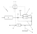
- the only attached figure shows a fuel cell system with a gas generation system indicated in principle.
- the core of a fuel cell system 1 forms a fuel cell 2 with an anode compartment 3, a cathode compartment 4 and one of the anode compartment 3 from the cathode compartment 4 separating membrane 5.
- the so-called reformate stream serves a well-known Gas generation system 6, in which the reformate, for example generated from liquid hydrocarbons becomes.
- This reformate current then flows through the anode compartment 3 of the fuel cell 2 and arrives in the direction of flow after the fuel cell in the area of a catalytic burner 7.
- air conveyed through the cathode compartment 4 of the fuel cell being the gas stream of air or another oxygen-containing gas after the fuel cell 2 with the gas stream flowing through the anode compartment 3 is mixed so that the gas flows together to the reach catalytic burner 7.
- the fuel cell system 1 can also have a bypass line 8 to the anode compartment 3 of the fuel cell 2, whose function will be discussed in more detail later becomes.
- the bypass line 8 is dashed shown, since their existence is only one Option shown and the bypass line 8 only at corresponding boundary conditions in the fuel cell system 1 is needed at all.
- the fuel cell system 1 also has an optional one Supply line 9 for an additional fuel, for example methanol or hydrogen, at least one of the gas flows in the flow direction between the fuel cell 2 and the catalytic burner 7 on.
- the additional fuel can be supplied via the feed line 9 metered into the area of the catalytic burner 7 if necessary.
- a corresponding one Use case could for example Start of the gas generating system 6 occur, which in another option at least in part by the catalytic burner 7 supplied with thermal energy could be.
- a is in the fuel cell system 1 Temperature sensor 10 shown, which shows the temperature profile in or in the area of the exhaust gases after the catalytic Burner 7 detected.
- the from the temperature sensor 10 acquired data will be a corresponding one Control device 11 supplied, which among other things the electrical commissioning the fuel cell 2 controls.
- On that known electrical connection of the fuel cell 2 in a corresponding circuit with at least an electrical power consumer is said to be here not be discussed in more detail, as this is known per se is.
- the presentation of corresponding electrical connections or the like in the area of the fuel cell indicated in principle 2 waived.
- the catalytic burner 7 over air, which promoted through the cathode chamber 4 in the fuel cell 2 is and introduced via the feed line 9 additional fuel heated to the required thermal energy to start the gas generation system to provide.
- the gas generation system 6 then becomes a corresponding one Deliver reformate, which at the beginning none or only will contain a very small amount of hydrogen.
- the reformate is very rich in this phase corresponding additives, such as nitrogen, carbon dioxide, Carbon monoxide, water and residues of the liquid Hydrocarbon which is in the gas generation system 6 is implemented.
- the gas generation system 6 now provides a sufficient level large amount of reformate with a sufficient large concentration of hydrogen available, this will be according to the flow paths described above also to the catalytic burner 7 reach.
- the temperature in the range of the catalytic Burner 7 and / or immediately after the catalytic Burner, which is detected by the temperature sensor 10 will increase accordingly in this case.
- the electrical commissioning would then have to be done accordingly the fuel cell 2 based on the temperature profile in the area of the catalytic burner 7 in two stages.
- reformate pressure valve not shown here, which throttles the reformate flow accordingly to in the gas generation system 6 compared to the ambient pressure to achieve increased pressure levels.
- the fuel cell 2 After successful electrical commissioning the fuel cell 2 can then the desired electrical Electricity can be requested in the specified manner.
- the temperature in the gas generation system 6 monitor and also the gas generation system 6 amount of fuel supplied with increasing Increase temperature in the gas generation system 6. There the fuel turnover in the gas generation system 6 from the Current temperature can depend on this procedure the maximum amount of fuel supplied and thus the time until the commissioning of the Fuel cell 2 can be reduced.
Landscapes
- Life Sciences & Earth Sciences (AREA)
- Engineering & Computer Science (AREA)
- Manufacturing & Machinery (AREA)
- Sustainable Development (AREA)
- Sustainable Energy (AREA)
- Chemical & Material Sciences (AREA)
- Chemical Kinetics & Catalysis (AREA)
- Electrochemistry (AREA)
- General Chemical & Material Sciences (AREA)
- Fuel Cell (AREA)
- Hydrogen, Water And Hydrids (AREA)
Abstract
Description
Claims (12)
- Verfahren zur elektrischen Inbetriebnahme einer Brennstoffzelle in einer Brennstoffzellenanlage, insbesondere für den Einsatz in einem Kraftfahrzeug, mit einem einen wasserstoffhaltigen Gasstrom erzeugenden Gaserzeugungssystem, wobei der Gasstrom aus dem Gaserzeugungssystem und ein sauerstoffhaltiger Gasstrom nach der Brennstoffzelle zusammengeführt und verbrannt werden,
dadurch gekennzeichnet, daß
die elektrischen Inbetriebnahme der Brennstoffzelle (2) in Abhängigkeit eines im Bereich der Verbrennung der Gasströme vorliegenden Temperaturverlaufs (Temperatursensor 10) erfolgt. - Verfahren nach Anspruch 1,
dadurch gekennzeichnet, daß
die Gasströme katalytisch (katalytischer Brenner 7) verbrannt werden. - Verfahren nach Anspruch 1 oder 2,
dadurch gekennzeichnet, daß
die Gasströme unter Zufuhr eines weiteren Brennstoffs (Zuleitung 9) verbrannt werden. - Verfahren nach Anspruch 1, 2 oder 3,
dadurch gekennzeichnet, daß
die elektrische Inbetriebnahme der Brennstoffzelle (2) durch elektrisches Zuschalten der Brennstoffzelle (2) in einem Stromkreis mit wenigstens einem Stromverbraucher erfolgt. - Verfahren nach einem der Ansprüche 1 bis 4,
dadurch gekennzeichnet, daß
der sauerstoffhaltige Gasstrom durch einen Kathodenraum (4) der Brennstoffzelle (2) geleitet wird, und daß der Gasstrom aus dem Gaserzeugungssystem (6) bereits vor der elektrischen Inbetriebnahme der Brennstoffzelle (2) durch einen Anodenraum (3) der Brennstoffzelle (2) geleitet wird. - Verfahren nach einem der Ansprüche 1 bis 4,
dadurch gekennzeichnet, daß
der sauerstoffhaltige Gasstrom durch einen Kathodenraum (4) der Brennstoffzelle (2) geleitet wird, und daß der Gasstrom aus dem Gaserzeugungssystem (6) vor der Inbetriebnahme der Brennstoffzelle (2) über eine Bypassleitung (8) an der Brennstoffzelle (2) vorbeigeleitet wird, wobei zur elektrischen Inbetriebnahme zumindest ein Teil des aus den Gaserzeugungssystem (6) stammenden Gasstroms in einen Anodenraum (3) der Brennstoffzelle (2) geleitet wird. - Verfahren nach einem der Ansprüche 1 bis 6,
dadurch gekennzeichnet, daß
die Inbetriebnahme der Brennstoffzelle (2) bei Umgebungsdruck erfolgt. - Verfahren nach einem der Ansprüche 1 bis 7,
dadurch gekennzeichnet, daß
die elektrische Inbetriebnahme der Brennstoffzelle (2) erfolgt, sobald die Temperatur (Sensor 10) der Verbrennung einen bestimmten, vorgegebenen Wert erreicht. - Verfahren nach einem der Ansprüche 3 bis 7,
dadurch gekennzeichnet, daß
die elektrische Inbetriebnahme der Brennstoffzelle (2) erfolgt, sobald die zugeführte Menge an Brennstoff bei vollständiger Verbrennung und konstantem Temperaturverlauf einen vorgegebenen Wert erreicht. - Verfahren nach einem der Ansprüche 1 bis 6,
dadurch gekennzeichnet, daß
die elektrische Inbetriebnahme der Brennstoffzelle (2) bei einem gegenüber dem Umgebungsdruck erhöhten Druckniveau erfolgt. - Verfahren nach Anspruch 10,
dadurch gekennzeichnet, daß
die elektrische Inbetriebnahme der Brennstoffzelle (2) erfolgt, wenn der Temperaturverlauf nach einem ersten Abfallen der Temperatur wegen einer Drosselung des aus dem Gaserzeugungssystem (6) stammenden Gasstroms zwecks Aufbau des erhöhten Druckniveaus erneut ansteigt, und einen vorgegebenen Wert erreicht. - Verfahren nach Anspruch 1,
dadurch gekennzeichnet, daß
zusätzlich die Temperatur im Gaserzeugungssystem (6) überwacht wird und daß die dem Gaserzeugungssystem (6) zugeführte Brennstoffmenge mit zunehmender Temperatur erhöht wird.
Applications Claiming Priority (2)
| Application Number | Priority Date | Filing Date | Title |
|---|---|---|---|
| DE10054842 | 2000-11-04 | ||
| DE10054842A DE10054842A1 (de) | 2000-11-04 | 2000-11-04 | Verfahren zur elektrischen Inbetriebnahme einer Brennstoffzelle |
Publications (3)
| Publication Number | Publication Date |
|---|---|
| EP1205991A2 true EP1205991A2 (de) | 2002-05-15 |
| EP1205991A3 EP1205991A3 (de) | 2005-05-11 |
| EP1205991B1 EP1205991B1 (de) | 2006-06-21 |
Family
ID=7662226
Family Applications (1)
| Application Number | Title | Priority Date | Filing Date |
|---|---|---|---|
| EP01124952A Expired - Lifetime EP1205991B1 (de) | 2000-11-04 | 2001-10-19 | Verfahren zur elektrischen Inbetriebnahme einer Brennstoffzelle |
Country Status (3)
| Country | Link |
|---|---|
| US (1) | US7214437B2 (de) |
| EP (1) | EP1205991B1 (de) |
| DE (2) | DE10054842A1 (de) |
Cited By (2)
| Publication number | Priority date | Publication date | Assignee | Title |
|---|---|---|---|---|
| EP1542305A1 (de) * | 2003-12-08 | 2005-06-15 | Proton Motor Fuel Cell GmbH | System und Verfahren zur Entfernung von Wasserstoff aus Brennstoffzellen-Abgasen |
| EP1919018A1 (de) | 2006-09-28 | 2008-05-07 | J. Eberspächer GmbH & Co. KG | Brennstoffzellensystem |
Families Citing this family (3)
| Publication number | Priority date | Publication date | Assignee | Title |
|---|---|---|---|---|
| US7001682B2 (en) * | 2002-06-24 | 2006-02-21 | Delphi Technologies, Inc. | Solid-oxide fuel cell system having means for controlling tail gas combustion temperature |
| DE10231884A1 (de) * | 2002-07-12 | 2004-02-05 | Viessmann Werke Gmbh & Co Kg | Apparat zur Erzeugung von Wasserstoff |
| DE10349075B4 (de) | 2003-10-22 | 2016-01-07 | Airbus Operations Gmbh | Vorrichtung zur Zufuhr von Brennstoff zu einem Brenner in einem Brennstoffzellensystem mit einem Reformer |
Family Cites Families (13)
| Publication number | Priority date | Publication date | Assignee | Title |
|---|---|---|---|---|
| US4041210A (en) * | 1976-08-30 | 1977-08-09 | United Technologies Corporation | Pressurized high temperature fuel cell power plant with bottoming cycle |
| JPS5823169A (ja) * | 1981-08-03 | 1983-02-10 | Hitachi Ltd | 燃料電池発電装置およびその運転方法 |
| US4473622A (en) * | 1982-12-27 | 1984-09-25 | Chludzinski Paul J | Rapid starting methanol reactor system |
| JPS6188460A (ja) * | 1984-10-05 | 1986-05-06 | Fuji Electric Co Ltd | 燃料電池発電システムの起動方法 |
| JPS6222374A (ja) * | 1985-07-19 | 1987-01-30 | Sanyo Electric Co Ltd | 加圧式燃料電池の起動方法 |
| JP2511866B2 (ja) * | 1986-02-07 | 1996-07-03 | 株式会社日立製作所 | 燃料電池発電システム及びその起動方法 |
| JPS6345766A (ja) * | 1986-08-13 | 1988-02-26 | Fuji Electric Co Ltd | 燃料電池発電装置 |
| JPH02158061A (ja) * | 1988-12-12 | 1990-06-18 | Fuji Electric Co Ltd | 燃料電池発電システムの起動方法 |
| ATA67396A (de) * | 1996-04-15 | 1999-01-15 | Vaillant Gmbh | Katalytischer erdgasbrenner |
| US6063515A (en) * | 1997-12-22 | 2000-05-16 | Ballard Power Systems Inc. | Integrated fuel cell electric power generation system for submarine applications |
| US6329089B1 (en) * | 1997-12-23 | 2001-12-11 | Ballard Power Systems Inc. | Method and apparatus for increasing the temperature of a fuel cell |
| US6472092B1 (en) * | 1998-08-12 | 2002-10-29 | Honda Giken Kogyo Kabushiki Kaisha | Fuel-reforming apparatus comprising a plate-shaped reforming catalyst |
| US6451465B1 (en) * | 2000-02-07 | 2002-09-17 | General Motors Corporation | Method for operating a combustor in a fuel cell system |
-
2000
- 2000-11-04 DE DE10054842A patent/DE10054842A1/de not_active Withdrawn
-
2001
- 2001-10-19 EP EP01124952A patent/EP1205991B1/de not_active Expired - Lifetime
- 2001-10-19 DE DE50110229T patent/DE50110229D1/de not_active Expired - Lifetime
- 2001-11-05 US US09/985,643 patent/US7214437B2/en not_active Expired - Fee Related
Cited By (2)
| Publication number | Priority date | Publication date | Assignee | Title |
|---|---|---|---|---|
| EP1542305A1 (de) * | 2003-12-08 | 2005-06-15 | Proton Motor Fuel Cell GmbH | System und Verfahren zur Entfernung von Wasserstoff aus Brennstoffzellen-Abgasen |
| EP1919018A1 (de) | 2006-09-28 | 2008-05-07 | J. Eberspächer GmbH & Co. KG | Brennstoffzellensystem |
Also Published As
| Publication number | Publication date |
|---|---|
| EP1205991A3 (de) | 2005-05-11 |
| US7214437B2 (en) | 2007-05-08 |
| DE10054842A1 (de) | 2002-08-29 |
| US20020058166A1 (en) | 2002-05-16 |
| DE50110229D1 (de) | 2006-08-03 |
| EP1205991B1 (de) | 2006-06-21 |
Similar Documents
| Publication | Publication Date | Title |
|---|---|---|
| DE10107127B4 (de) | Brennstoffzellensystem und Verfahren zum Steuern des Brennstoffzellensystems | |
| EP3994294B1 (de) | Soec-system und verfahren zum betreiben eines soec-systems | |
| AT521209B1 (de) | Brennstoffzellensystem, stationäres Kraftwerk sowie Verfahren zum Betreiben eines Brennstoffzellensystems | |
| DE10106803B4 (de) | Reformer-Steuerungsvorrichtung und Verfahren zum Steuern eines Reformers | |
| EP3033789B1 (de) | Vereinfachung des elektrischen systems von brennstoffzellen durch verarmung der kathodenversorgung | |
| EP1947723B1 (de) | Energiebereitstellungssystem | |
| EP1205991B1 (de) | Verfahren zur elektrischen Inbetriebnahme einer Brennstoffzelle | |
| DE2836464C3 (de) | Wasserstoff/Sauerstoff-Brennstoffbatterie | |
| DE102020215560A1 (de) | Verfahren zum Erkennen von Verstopfungen innerhalb eines Brennstoffzellensystems | |
| CH696413A5 (de) | Brennstoffzellenanlage. | |
| EP1519894A2 (de) | Verfahren zum starten eines gaserzeugungssystems | |
| AT521901B1 (de) | Verfahren zum Aufheizen eines Brennstoffzellensystems sowie Brennstoffzellensystem | |
| EP1919018B1 (de) | Brennstoffzellensystem | |
| AT518956B1 (de) | Verfahren zum herunterfahren einer generatoreinheit mit einer brennstoffzellenvorrichtung | |
| DE102007048865B4 (de) | Brennstoffzellenanordnung und Verfahren zum Mischen von Wasserstoff und Luft in einer Brennstoffzellenanordnung | |
| DE19958830B4 (de) | Brennstoffzellensystem sowie dessen Verwendung | |
| DE10141776A1 (de) | Verfahren zum Starten eines katalytischen Reaktors | |
| EP1739776A1 (de) | Verfahren zur Zuführung von Betriebsgas zu einem Gasraum einer Brennstoffzelle sowie Brennstoffzelle | |
| DE10349075B4 (de) | Vorrichtung zur Zufuhr von Brennstoff zu einem Brenner in einem Brennstoffzellensystem mit einem Reformer | |
| EP1986262B1 (de) | Kalibrierverfahren für eine Brennstoffzellensteuerung | |
| EP1575113A2 (de) | Brennstoffzellenanordnung | |
| DE102008005838B4 (de) | Kraftfahrzeug mit Reformer | |
| WO2009049779A1 (de) | Verfahren zum betreiben eines brennstoffzellensystems | |
| DE10141903A1 (de) | Vorrichtung zur Versorgung eines Brennstoffzellensystems mit einem sauerstoffhaltigen Medium | |
| DE102022207013A1 (de) | Verfahren zum Starten eines Brennstoffzellensystems |
Legal Events
| Date | Code | Title | Description |
|---|---|---|---|
| PUAI | Public reference made under article 153(3) epc to a published international application that has entered the european phase |
Free format text: ORIGINAL CODE: 0009012 |
|
| AK | Designated contracting states |
Kind code of ref document: A2 Designated state(s): AT BE CH CY DE DK ES FI FR GB GR IE IT LI LU MC NL PT SE TR |
|
| AX | Request for extension of the european patent |
Free format text: AL;LT;LV;MK;RO;SI |
|
| RAP1 | Party data changed (applicant data changed or rights of an application transferred) |
Owner name: BALLARD POWER SYSTEMS AG |
|
| PUAL | Search report despatched |
Free format text: ORIGINAL CODE: 0009013 |
|
| AK | Designated contracting states |
Kind code of ref document: A3 Designated state(s): AT BE CH CY DE DK ES FI FR GB GR IE IT LI LU MC NL PT SE TR |
|
| AX | Request for extension of the european patent |
Extension state: AL LT LV MK RO SI |
|
| RAP1 | Party data changed (applicant data changed or rights of an application transferred) |
Owner name: NUCELLSYS GMBH |
|
| 17P | Request for examination filed |
Effective date: 20051108 |
|
| GRAP | Despatch of communication of intention to grant a patent |
Free format text: ORIGINAL CODE: EPIDOSNIGR1 |
|
| AKX | Designation fees paid |
Designated state(s): DE FR GB IT |
|
| GRAS | Grant fee paid |
Free format text: ORIGINAL CODE: EPIDOSNIGR3 |
|
| GRAA | (expected) grant |
Free format text: ORIGINAL CODE: 0009210 |
|
| AK | Designated contracting states |
Kind code of ref document: B1 Designated state(s): DE FR GB IT |
|
| PG25 | Lapsed in a contracting state [announced via postgrant information from national office to epo] |
Ref country code: IT Free format text: LAPSE BECAUSE OF FAILURE TO SUBMIT A TRANSLATION OF THE DESCRIPTION OR TO PAY THE FEE WITHIN THE PRESCRIBED TIME-LIMIT;WARNING: LAPSES OF ITALIAN PATENTS WITH EFFECTIVE DATE BEFORE 2007 MAY HAVE OCCURRED AT ANY TIME BEFORE 2007. THE CORRECT EFFECTIVE DATE MAY BE DIFFERENT FROM THE ONE RECORDED. Effective date: 20060621 |
|
| REG | Reference to a national code |
Ref country code: GB Ref legal event code: FG4D Free format text: NOT ENGLISH |
|
| REF | Corresponds to: |
Ref document number: 50110229 Country of ref document: DE Date of ref document: 20060803 Kind code of ref document: P |
|
| GBT | Gb: translation of ep patent filed (gb section 77(6)(a)/1977) |
Effective date: 20060924 |
|
| ET | Fr: translation filed | ||
| PLBE | No opposition filed within time limit |
Free format text: ORIGINAL CODE: 0009261 |
|
| STAA | Information on the status of an ep patent application or granted ep patent |
Free format text: STATUS: NO OPPOSITION FILED WITHIN TIME LIMIT |
|
| 26N | No opposition filed |
Effective date: 20070322 |
|
| PGFP | Annual fee paid to national office [announced via postgrant information from national office to epo] |
Ref country code: FR Payment date: 20091110 Year of fee payment: 9 Ref country code: GB Payment date: 20091022 Year of fee payment: 9 Ref country code: IT Payment date: 20091023 Year of fee payment: 9 |
|
| PGFP | Annual fee paid to national office [announced via postgrant information from national office to epo] |
Ref country code: DE Payment date: 20110311 Year of fee payment: 10 |
|
| GBPC | Gb: european patent ceased through non-payment of renewal fee |
Effective date: 20101019 |
|
| PG25 | Lapsed in a contracting state [announced via postgrant information from national office to epo] |
Ref country code: FR Free format text: LAPSE BECAUSE OF NON-PAYMENT OF DUE FEES Effective date: 20101102 |
|
| REG | Reference to a national code |
Ref country code: FR Ref legal event code: ST Effective date: 20110630 |
|
| PG25 | Lapsed in a contracting state [announced via postgrant information from national office to epo] |
Ref country code: GB Free format text: LAPSE BECAUSE OF NON-PAYMENT OF DUE FEES Effective date: 20101019 |
|
| PG25 | Lapsed in a contracting state [announced via postgrant information from national office to epo] |
Ref country code: IT Free format text: LAPSE BECAUSE OF NON-PAYMENT OF DUE FEES Effective date: 20101019 |
|
| PG25 | Lapsed in a contracting state [announced via postgrant information from national office to epo] |
Ref country code: DE Free format text: LAPSE BECAUSE OF NON-PAYMENT OF DUE FEES Effective date: 20120501 |
|
| REG | Reference to a national code |
Ref country code: DE Ref legal event code: R119 Ref document number: 50110229 Country of ref document: DE Effective date: 20120501 |