EP1205899A2 - Simulation methods and systems for the installation and the operation of a medical image diagnostic device - Google Patents
Simulation methods and systems for the installation and the operation of a medical image diagnostic device Download PDFInfo
- Publication number
- EP1205899A2 EP1205899A2 EP01309546A EP01309546A EP1205899A2 EP 1205899 A2 EP1205899 A2 EP 1205899A2 EP 01309546 A EP01309546 A EP 01309546A EP 01309546 A EP01309546 A EP 01309546A EP 1205899 A2 EP1205899 A2 EP 1205899A2
- Authority
- EP
- European Patent Office
- Prior art keywords
- medical image
- diagnostic device
- image diagnostic
- installing
- imaging
- Prior art date
- Legal status (The legal status is an assumption and is not a legal conclusion. Google has not performed a legal analysis and makes no representation as to the accuracy of the status listed.)
- Withdrawn
Links
- 238000004088 simulation Methods 0.000 title claims abstract description 134
- 238000009434 installation Methods 0.000 title claims abstract description 64
- 238000000034 method Methods 0.000 title claims description 49
- 238000003384 imaging method Methods 0.000 claims abstract description 107
- 235000004522 Pentaglottis sempervirens Nutrition 0.000 abstract description 14
- 238000004891 communication Methods 0.000 description 13
- 238000002595 magnetic resonance imaging Methods 0.000 description 12
- 230000006870 function Effects 0.000 description 11
- 238000010586 diagram Methods 0.000 description 9
- 238000012545 processing Methods 0.000 description 8
- 238000002591 computed tomography Methods 0.000 description 6
- 238000012508 change request Methods 0.000 description 3
- 238000002604 ultrasonography Methods 0.000 description 3
- 238000010276 construction Methods 0.000 description 2
- 238000013461 design Methods 0.000 description 2
- 238000011156 evaluation Methods 0.000 description 2
- 230000003247 decreasing effect Effects 0.000 description 1
- 230000000694 effects Effects 0.000 description 1
- 238000001208 nuclear magnetic resonance pulse sequence Methods 0.000 description 1
- 238000002601 radiography Methods 0.000 description 1
Images








Classifications
-
- G—PHYSICS
- G09—EDUCATION; CRYPTOGRAPHY; DISPLAY; ADVERTISING; SEALS
- G09B—EDUCATIONAL OR DEMONSTRATION APPLIANCES; APPLIANCES FOR TEACHING, OR COMMUNICATING WITH, THE BLIND, DEAF OR MUTE; MODELS; PLANETARIA; GLOBES; MAPS; DIAGRAMS
- G09B23/00—Models for scientific, medical, or mathematical purposes, e.g. full-sized devices for demonstration purposes
- G09B23/28—Models for scientific, medical, or mathematical purposes, e.g. full-sized devices for demonstration purposes for medicine
-
- Y—GENERAL TAGGING OF NEW TECHNOLOGICAL DEVELOPMENTS; GENERAL TAGGING OF CROSS-SECTIONAL TECHNOLOGIES SPANNING OVER SEVERAL SECTIONS OF THE IPC; TECHNICAL SUBJECTS COVERED BY FORMER USPC CROSS-REFERENCE ART COLLECTIONS [XRACs] AND DIGESTS
- Y02—TECHNOLOGIES OR APPLICATIONS FOR MITIGATION OR ADAPTATION AGAINST CLIMATE CHANGE
- Y02A—TECHNOLOGIES FOR ADAPTATION TO CLIMATE CHANGE
- Y02A90/00—Technologies having an indirect contribution to adaptation to climate change
- Y02A90/10—Information and communication technologies [ICT] supporting adaptation to climate change, e.g. for weather forecasting or climate simulation
Definitions
- the present invention relates to an installation simulation method of a medical image diagnostic device, an operation simulation method, an imaging simulation method, systems, programs and a recording medium. More specifically, the present invention relates to an installation simulation method which can automatically display an installing image of a medical image diagnostic device, an operation simulation method which can experience in a simulated manner the operation of the medical image diagnostic device, an imaging simulation method which can experience in a simulated manner imaging of the medical image diagnostic device, systems for executing the simulation methods, programs, and a recording medium for recording them.
- a large medical image diagnostic device such as an MRI device or an X-ray CT device
- the customer must check the size of the medical image diagnostic device in a catalog to examine whether it can be installed into the imaging room or not.
- the customer notifies information on the dimensions (width, depth and height) the imaging room and the model to the sales person in charge of the Vendor to ask the sales person to create an installing image, and referring to-the installing image, finally decides whether it can be introduced or not.
- the customer browses, for example, a home page released on the Internet by the Vendor, e.g., the screen as shown in FIG. 18 to grasp the construction of the medical image diagnostic device.
- the part "Magnet” underlined is only clicked to jump to a link destination, so as to browse the detailed description of the "Magnet", as shown in FIG. 19.
- the construction or features of the medical image diagnostic device can be understood to some degree on the home page, but the operation feeling is difficult to grasp.
- a first object of the present invention is to provide an installation simulation method which can automatically display an installing image of a medical image diagnostic device, system, program, and a recording medium recording the same.
- a second object of the present invention is to provide an operation simulation method which can experience in a simulated manner the operation of a medical image diagnostic device, system, program, and a recording medium recording the same.
- a third object of the present invention is to provide an imaging simulation method which can experience in a simulated manner the imaging of a medical image diagnostic device, system, program, and a recording medium recording the same.
- the present invention provides an installation simulation method of a medical image diagnostic device comprising the steps of: specifying the dimensions of an installing space of a medical image diagnostic device; and generating and displaying an installing image when the medical image diagnostic device is installed virtually in the installing space.
- the installing image is displayed automatically.
- the customer can easily obtain and evaluate the installing image without any personal procedure. Unless the installing image is displayed, the customer can readily recognize that the medical image diagnostic device cannot be installed in the installing space.
- the present invention provides the thus-constructed installation simulation method of a medical image diagnostic device, further comprising the steps of: displaying candidates for a medical image diagnostic device installable in the installing space; and generating an installing image of the medical image diagnostic device selected from among those candidates.
- the present invention provides the thus-constructed installation simulation method of a medical image diagnostic device, wherein the installing image is at least one of a bird's eye view of the medical image diagnostic device looked down from above, a plan view of the medical image diagnostic device projected onto a plane, a front view of the medical image diagnostic device projected onto a front, a rear view of the medical image diagnostic device projected onto a rear, and a side view of the medical image diagnostic device projected onto a side.
- the placement state of the entire medical image diagnostic device in the installing space can be readily recognized.
- the placement state of the top (or bottom) surface of the medical image diagnostic device in the ceiling (or floor) surface of the installing space can be readily recognized.
- the present invention provides the thus-constructed installation simulation method of a medical image diagnostic device, wherein when a viewpoint change is instructed on the installing image, the installing image is generated again and displayed corresponding to the instruction.
- the installation simulation method of the fourth aspect is useful when the installing state is observed in a field of view different from the field of view corresponding to the installing image displayed.
- the viewpoint change is instructed so that the installing image displayed is updated to an installing image corresponding to a desired field of view.
- the present invention provides the thus-constructed installation simulation method of a medical image diagnostic device, wherein the medical image diagnostic device is at least one of an MRI (Magnetic Resonance Imaging) device, an X-ray CT (Computed Tomography) device, an ultrasound diagnostic device, a PET (Positron Emission computed Tomography) device, an X-ray imaging device, and a CR (Computed Radiography) device.
- MRI Magnetic Resonance Imaging
- X-ray CT Computed Tomography
- ultrasound diagnostic device e.g., a PET (Positron Emission computed Tomography) device
- PET Positron Emission computed Tomography
- X-ray imaging device e.g., X-ray imaging device
- CR Computed Radiography
- the installation simulation method can be preferably executed to various large medical image diagnostic devices (MRI device, X-ray CT device, PET device, X-ray imaging device and CR device).
- the ultrasound diagnostic device is not always a large device, but is relatively inexpensive with a wide range of uses and has many chances to change the model and to introduce a new type.
- the usability to execute the installation simulation method is high.
- the present invention provides an operation simulation method of a medical image diagnostic device comprising the step of generating and displaying an operation replay image replaying in a simulated manner the operation of a medical image diagnostic device corresponding to an operation request given on an image simulating an operation part of the medical image diagnostic device or an operation request given through an input device having a function equivalent to that of the operation part.
- the operation simulation method of the sixth aspect when the operation request is given through an image simulating the operation part or the input device, the operation replay image corresponding thereto is displayed.
- the operation of the medical image diagnostic device can be experienced in a simulated manner without using an actual medical image diagnostic device. Thus, it is possible to easily perform evaluation of operativity or practice of the operation at low cost.
- the present invention provides the thus-constructed operation simulation method of a medical image diagnostic device, wherein the operation of the medical image diagnostic device is replayed by reducing time.
- time required for the operation simulation can be saved to improve the efficiency.
- the present invention provides an imaging simulation method of a medical image diagnostic device comprising the step of displaying a medical image obtained when imaging of a medical image diagnostic device is performed virtually corresponding to an imaging request given on an image simulating an operation part of the medical image diagnostic device or an imaging request given through an input device having a function equivalent to that of the operation part.
- the imaging simulation method of the eighth aspect when the imaging request is given through an image simulating the operation part or an input device, the medical image is displayed as imaged virtually. Imaging of the medical image diagnostic device can be experienced in a simulated manner without using an actual medical image diagnostic device. Thus, it is possible to exactly recognize a procedure for setting the imaging conditions or a medical image obtained by imaging.
- the present invention provides the thus-constructed imaging simulation method, wherein the medical image is selected from among a plurality of dummy images previously prepared.
- the optimum medical image is selected from among a plurality of dummy images to be displayed. Complicated image generation computing is unnecessary, so that the medical image can be readily displayed.
- the present invention provides an installation simulation system of a medical image diagnostic device comprising: a customer side terminal; a host server device, and a network for connecting the customer side terminal to the host server device, wherein when the dimensions of an installing space of a medical image diagnostic device are specified by an operator, the customer side terminal sends the dimensions of the installing space through the network to the host server device, and wherein the host server device (or an arithmetic unit connected thereto) generates an installing image when the medical image diagnostic device is installed virtually in the installing space to send the installing image through the network to the customer side terminal, and displays the installing image on the screen of the customer side terminal.
- the installation simulation system of the tenth aspect can preferably execute the installation simulation method of the first aspect.
- the present invention provides an operation simulation system of a medical image diagnostic device comprising: a customer side terminal; a host server device, and a network for connecting the customer side terminal to the host server device, wherein the customer side terminal sends, through the network to the host server device, an operation request given on an image simulating an operation part of a medical image diagnostic device or an operation request given through an input device having a function equivalent to that of the operation part, and wherein the host server device (or an arithmetic unit connected thereto) generates an operation replay image replaying in a simulated manner the operation of a medical image diagnostic device corresponding to the operation request to send the operation replay image through the network to the customer side terminal, and displays the operation replay image on the screen of the customer side terminal.
- the operation simulation system of the eleventh aspect can preferably execute the operation simulation method of the sixth aspect.
- the present invention provides an imaging simulation system of a medical image diagnostic device comprising: a customer side terminal; a host server device, and a network for connecting the customer side terminal to the host server device, wherein the customer side terminal sends, through the network to the host server device, an imaging request given on an image simulating an operation part of a medical image diagnostic device or an imaging request given through an input device having a function equivalent to that of the operation part, and wherein the host server device (or an arithmetic unit connected thereto) sends, through the network to the customer side terminal, a medical image obtained when the medical image diagnostic device virtually performs imaging corresponding to the imaging request to display the medical image on the screen of the customer side terminal.
- the imaging simulation system of the twelfth aspect can preferably execute the imaging simulation method of the eighth aspect.
- the present invention provides an installation simulation program of a medical image diagnostic device which describes, in a code form executed by a computer, a dimension input step for inputting the dimensions of an installing space of a medical image diagnostic device, an installing image generation step for generating an installing image when the medical image diagnostic device is installed virtually in the installing space, and an installing image display step for displaying the installing image.
- the installation simulation program of the thirteenth aspect can preferably execute the installation simulation method of the first aspect.
- the present invention provides an operation simulation program of a medical image diagnostic device which describes, in a code form executed by a computer, an operation request reception step for receiving an operation request given on an image simulating an operation part of a medical image diagnostic device or an operation request given through an input device having a function equivalent to that of the operation part, an operation replay image generation step for generating an operation replay image replaying in a simulated manner the operation of a medical image diagnostic device corresponding to the operation request, and an operation replay image display step for displaying the operation replay image.
- the operation simulation program of the fourteenth aspect can preferably execute the operation simulation method of the sixth aspect.
- the present invention provides an imaging simulation program of a medical image diagnostic device which describes, in a code form executed by a computer, an imaging request reception step for receiving an imaging request given on an image simulating an operation part of a medical image diagnostic device or an imaging request given through an input device having a function equivalent to that of the operation part, and a medical image display step for displaying a medical image obtained when the medical image diagnostic device virtually performs imaging corresponding to the imaging request.
- the imaging simulation program of the fifteenth aspect can preferably execute the imaging simulation method of the eighth aspect.
- the present invention provides a recording medium recording at least one of the thus-constructed installation simulation program, the thus-constructed operation simulation program, and the thus-constructed imaging simulation program.
- the recording medium of the sixteenth aspect can preferably execute the installation simulation methods of the first, sixth and eighth aspects.
- an installing image showing a state where a medical image diagnostic device is installed in an installing space of the specified dimensions can be displayed automatically.
- an image simulating an operation part or an input device is used to experience in a simulated manner the operation of a medical image diagnostic device.
- an image simulating an operation part or an input device is used to experience in a simulated manner the imaging of a medical image diagnostic device.
- FIG. 1 is a block diagram showing an installation simulation system 1000 of a medical image diagnostic device according to a first embodiment of the present invention.
- the installation simulation system 1000 has a network 1 such as Internet, LAN (Local Area Network), and WAN (Wide Area Network), customer side terminals 11, 12, 13 and 14 connected to the network 1 (which may be located in the same or different place), a host server device 100, and an arithmetic unit 101.
- the host server device 100 is connected to the arithmetic unit 101 through a communication line 102 such as LAN.
- the customer side terminals 11 to 14 are, for example, personal computers installing Web Browser.
- Web Browser Internet Explorer (manufactured by Microsoft Corporation) and Netscape Navigator (manufactured by Netscape Communications Corporation) are widespread.
- the network 1 is Internet
- a large number of terminals other than the customer side terminals 11 to 14 are also connected to the network 1.
- SSL Secure Socket Layer Protocol
- the like are preferably used.
- FIG. 2 is a block diagram of the host server device 100 and the arithmetic unit 101.
- the host server device 100 has a communication part 10A, an input part 10B, an output part 10C, and an installation simulation Web Page storing part 10D for storing an installation simulation Web Page browsed by a customer, and is operated under control of a Web Page manage program.
- the recording medium of the installation simulation Web Page storing part 10D is, for example, a hard disk.
- the arithmetic unit 101 has a connection part 11A, an installing image generation part 110, and a viewpoint change click point decision part 11E, and is operated under control of an installation simulation manage program.
- the installing image generation part 110 has a bird's eye view generation part 11B, a front view generation part 11C, and a plan view generation part 11D.
- the "bird's eye view”, the "front view”, and the “plan view” are state explanation views of the medical image diagnostic device viewed from the respective directions when the medical image diagnostic device is installed virtually in the imaging room.
- the "viewpoint change click point” is a point for specifying the viewpoint position and the line of sight for viewing the medical image diagnostic device.
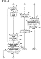
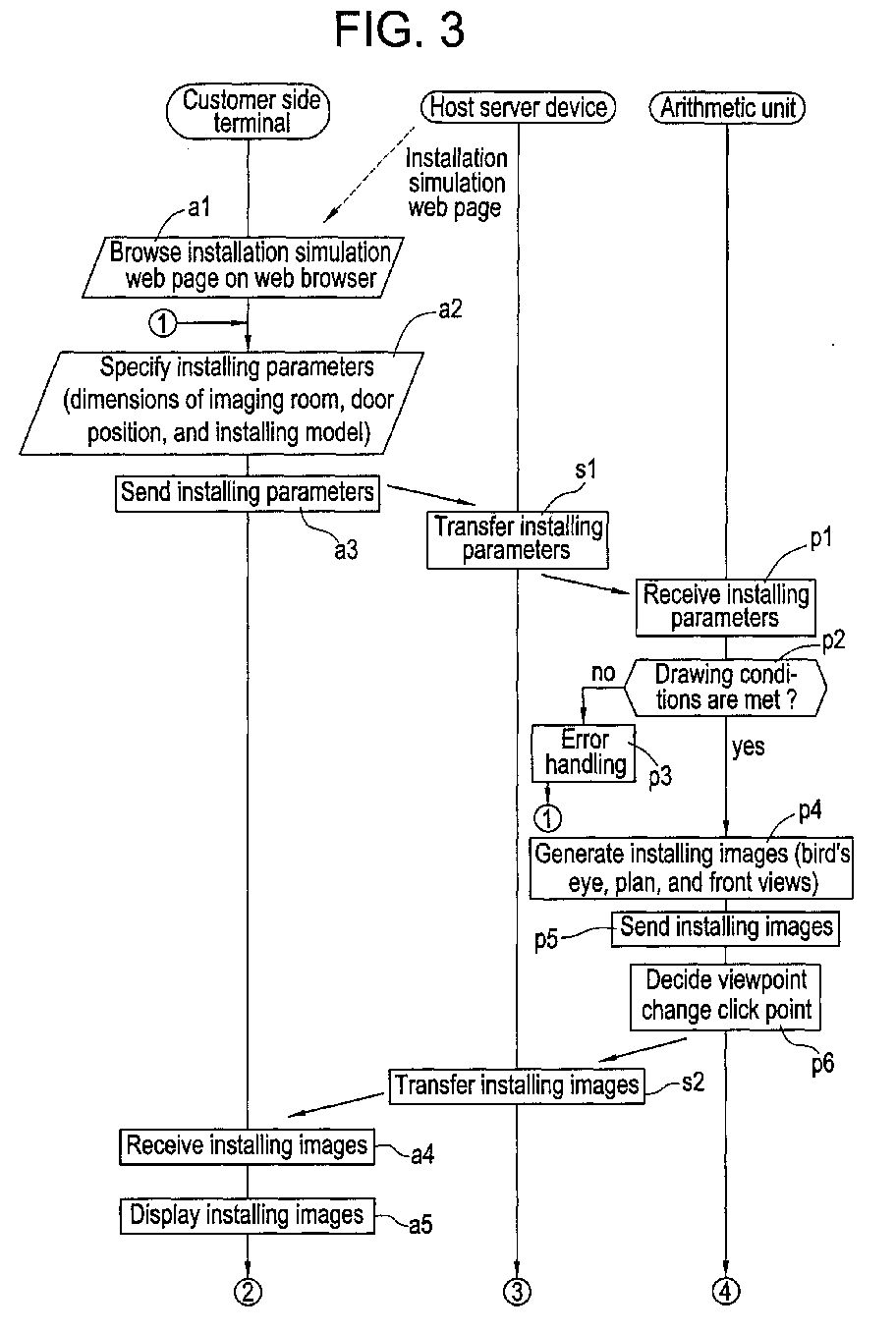
- FIGS. 3 and 4 are flowcharts showing the installation simulation processing of the medical image diagnostic device.
- the left side flow is a flow of a customer side terminal (envisaging the customer side terminal 11).
- the middle flow is a flow of the host server device 100.
- the right side flow is a flow of the arithmetic unit 101.
- step a1 the operator (customer) of the customer side terminal 11 accesses the host server device 100 through the network 1, and then, browses the installation simulation Web Page on the Web Browser.
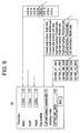
- the installation simulation Web Page screen G1 of FIG. 5 there is displayed a screen having an installing parameter display region R1 for specifying the dimensions of the imaging room, the door position, and the installing model of the medical image diagnostic device, and an installing image display region R2 for displaying an installing image when the medical image diagnostic device is installed virtually in the imaging room.
- the position of cursor ⁇ can optionally be moved by operation of a pointing device such as a mouse.
- step a2 the operator specifies installing parameters on the installation simulation Web Page screen G1.
- desired installing parameters are selected from the candidates displayed in a pull-down menu form.
- the illustration is an example in which "4.60m”, “7.60m”, and “3.80m” are selected as the width, depth, and height of the imaging room, "left wall surface, forward side” is selected as the door position, and "GEYMS_MR_6000" (the model name of the MRI device) is selected as the installing model.
- the installing model other than the MRI device for example, an X-ray CT device, an ultrasound diagnostic device, a PET device, an X-ray imaging device, or a CR device can be selected.
- step a3 the installing parameters are sent through the network 1 to the host server device 100.
- step s1 the host server device 100 transfers the installing parameters through the communication line 102 to the arithmetic unit 101.
- step p1 the arithmetic unit 101 receives the installing parameters.
- step p2 the arithmetic unit 101 judges whether the drawing conditions are met or not.
- the routine is advanced to step p4.
- the routine is advanced to step p3.
- the medical image diagnostic device as the installing model specified in the step a2 can be installed in the imaging room (by leaving the specified margin space), it is judged that the drawing conditions are met.
- the medical image diagnostic device lies off the imaging room or the margin space is insufficient, it is judged that the drawing conditions are not met.
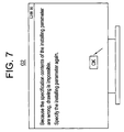
- step p3 error handling is performed. For example, as shown in the error message screen G2 of FIG. 7, the message "Because the specification contents of the installing parameter are wrong, drawing is impossible. Specify the installing parameter again.” is displayed.
- the arithmetic unit 101 generates installing images. That is, in the arithmetic unit 101, the bird's eye view generation part 11B generates a bird's eye view, the front view generation part 11C generates a front view, and the plan view generation part 11D generates a plan view.
- the viewpoint of the bird's eye view is the standard eye position of a human standing in the door position (for example, a height of 150cm from the floor surface).
- the specific example of the installing images will be described later with reference to FIG. 8.
- step p5 the position and the line of sight of the viewpoint change click points (Q1 to Q4 of FIG. 8) drawn into the bird's eye view are decided.
- step p6 the installing images are sent through the communication line 102 to the host server device 100.
- step s2 the host server device 100 transfers the installing images through the network 1 to the customer side terminal 11.
- step a4 the customer side terminal 11 receives the installing images.
- the installing image display region R2 of the installation simulation Web Page screen G1 displays the bird's eye view, the plan view and the front view (generally, the table inserting side surface viewed from the Magnet is regarded as the front) as the installing images.
- the rear view or the side view may be displayed.
- the plan view may include an operation room adjacent to the imaging room (a room for installing the console of the medical image diagnostic device).
- FIG. 8 illustrates an installation simulation Web Page screen G1' displaying the installing images.
- the viewpoint change click point Q1 corresponding to the field of view looking into a bore (a hollow in a gantry inserting a subject)
- the viewpoint change click point Q2 corresponding to the field of view of the subject placed on the top of the table
- the viewpoint change click point Q3 corresponding to the field of view in the bore
- the viewpoint change click point Q4 corresponding to the field of view looked down from above in a slanting direction.
- a link is provided in the respective components (the Magnet, table and so on) in the installing image.
- the function or PR Public Relations
- step a6 the customer side terminal 11 judges whether any one of the viewpoint change click points is clicked by the operator or not.
- the routine is advanced to step a7. Otherwise, the routine is advanced to step a10.
- step a7 a viewpoint change request is sent through the network 1 to the host server device 100.
- step s3 the host server device 100 transfers the viewpoint change request through the communication line 102 to the arithmetic unit 101.
- step p7 the arithmetic unit 101 receives the viewpoint change request.
- step p8 the installing image corresponding to the viewpoint change click point (any one of the Q1 to Q4) specified by the operator is generated again.
- step p9 the installing image is sent through the communication line 102 to the host server device 100.
- the installing image is sent through the communication line 102 to the host server device 100.
- only the bird's eye view may be sent.
- step s4 the host server device 100 transfers the bird's eye view through the network 1 to the customer side terminal 11.
- step a8 the customer side terminal 11 receives the installing image.
- step a9 the installing image display region R2 of the installation simulation Web Page screen G1 displays the received installing image.
- step a10 when the installation simulation is terminated, the installation simulation processing is terminated.
- the routine is advanced to a11.
- step a11 when any one of the installing parameters is to be changed, the routine is returned to the step a2.
- the change of the installing parameter is reflected on the installation simulation Web Page screen G1 to switch the display contents of the installing image of the installing image display region R2.
- the routine is returned to the step a6.
- the installing model field of the installing parameter display region R1 of the installation simulation Web Page screen G1 may display only the installing model installable in the imaging room of the specified dimensions in a pull-down menu form. In this case, the customer can readily recognize the installable installing model to quickly judge whether it can be installed or not. It is possible to prevent the error handling in the step p3 due to selection of an undrawable installing model.
- the customer simply specifies the model for the installation simulation and the dimensions of the imaging room on the installation simulation Web Page screen G1 displayed on the customer's own terminal (the numerals 11 to 14 of FIG. 1), thereby obtaining an installing image.
- the model for the installation simulation and the dimensions of the imaging room on the installation simulation Web Page screen G1 displayed on the customer's own terminal (the numerals 11 to 14 of FIG. 1), thereby obtaining an installing image.
- the installing image when the installing parameter is changed can be readily obtained, it is possible to easily perform comparison of the installing images for each model or evaluation of the installing state when the ceiling height or width of the imaging room is increased or decreased.
- FIG. 9 is a block diagram of a host server device 200 and an arithmetic unit 201 of an operation/imaging simulation system 2000 of a medical image diagnostic device according to a second embodiment of the present invention.
- the block diagram of the entire operation/imaging simulation system 2000 is similar to that of the installation simulation system 1000 of FIG. 1, and the illustration thereof is omitted.
- the host server device 200 has a communication part 10A, an input part 10B, an output part 10C, an operation simulation Web Page storing part 20D for storing an operation simulation Web Page browsed by a customer, and an imaging simulation Web Page storing part 20E for storing an imaging simulation Web Page browsed by a customer, and is operated under control of a Web Page manage program.
- the arithmetic unit 201 has a connection part 11A, an operation replay image generation part 21B for generating an image replaying the operation when the medical image diagnostic device is operated virtually, a dummy image storing part 21D for storing a dummy image of Pulse Sequence Design or for each scan parameter, and a dummy image selection part 21D for selecting the dummy image closest to an image expected to be generated by virtual imaging instructed by the operator, and is operated under control of an operation/imaging simulation manage program.
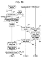
- FIGS. 10 and 11 are flowcharts showing the operation/imaging simulation processing of the medical image diagnostic device.
- the left side flow is a flow of the customer side terminal.
- the middle flow is a flow of the host server device 200.
- the right side flow is a flow of the arithmetic unit 201.
- step a21 the processing is branched corresponding to the simulation mode specified by the operator of the customer side terminal.
- the routine is advanced to step a22.
- the routine is advanced to step a31.
- step a22 the operator of the customer side terminal accesses the host server device 200 through the network 1 to browse the operation simulation Web Page on the Web Browser.
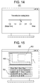
- the operation simulation Web Page screen G20 of FIG. 12 there is displayed a screen having an operation replay image display region R21 for displaying the MRI device for the operation simulation, and an operation switch display region R22 for displaying in a simulated manner the operation switch of the MRI device.
- the operation switch display region R22 displays "Up” button for raising the table (and the table top), “Down” button for lowering the table, "In” button for moving the table top in the direction inserting the same into the Magnet device, “Out” button for moving the table top in the direction removing the same from the Magnet device, and "Alignment Light” button for turning on/out a light for positioning a subject.
- the size and design of the respective buttons are preferably the same as those of an actual object where possible in view of closing the operating feeling to the actual object (which may be different from those of the actual object due to the screen region and so on).
- step a23 when any one of the operation buttons of the operation switch display region R22 of the installation simulation Web Page screen G20 is clicked by the operator, an operation request is sent through the network 1 to the host server device 200.
- step s21 the host server device 200 transfers the operation request through the communication line 102 to the arithmetic unit 201.
- step p21 the arithmetic unit 201 receives the operation request.
- step p22 the operation replay image generation part 21B of the arithmetic unit 201 generates an operation replay image corresponding to the operation request.
- step p23 the operation replay image is displayed through the communication line 101 to the host server device 200.
- step s22 the host server device 200 transfers the operation replay image through the network 1 to the customer side terminal.
- step a24 the customer side terminal receives the operation replay image.
- the operation replay image display region of the operation simulation Web Page screen displays the operation replay image.
- the operation replay image display region R21 displays a moving image in which the table top of the MRI device is moved in the direction inserting the same into the Magnet device. It depends on the model of the medical image diagnostic device whether the table is advanced only during depression of the button or the table is advanced to the limiting point when the button is pressed once and the hand is left from the button. In view of closing the operating feeling to the actual object, the model of the medical image diagnostic device is preferably the same as that of the operation simulation (depression of the pointing device button is equivalent to the depression of the button of the actual object).
- the table top moving speed may be matched with the actual moving speed, but it may be displayed by reducing the actual time.
- the adjust knob is slid to preferably vary the time reduction scaling factor.
- step a26 when the simulation is terminated, the operation/imaging simulation processing is terminated.
- the routine is returned to the step a21.
- step a31 the operator of the customer side terminal accesses the host server device 200 through the network 1 to browse the imaging simulation Web Page on the Web Browser.
- the operator of the customer side terminal accesses the host server device 200 through the network 1 to browse the imaging simulation Web Page on the Web Browser.
- the operation simulation Web Page screen G30 of FIG. 15 there is displayed an image having a console display region R31 for displaying in a simulated manner the console (keyboard) of the MRI device, a scan parameter display region R32 for displaying a scan parameter, and a dummy image display region R33 for displaying a dummy image.
- the image of the console display region R31 can be omitted (only the function buttons allocated to the function keys may be displayed on the screen).
- an input device such as a track ball is attached to the actual MRI device, it is also preferably displayed operatively on the screen.
- An image simulating an LED (Light-Emitting Diode) display indicating the table top position may be further displayed.
- step a32 the operator performs button operation on the console display region R31 of the imaging simulation Web Page screen G30 by mouse operation to set a scan parameter required for imaging.
- the scan parameter is reflected to the scan parameter display region R32.
- step a33 the customer side terminal sends the scan parameter through the network 1 to the host server device 200.
- step s31 the host server device 200 transfers the scan parameter through the communication line 102 to the arithmetic unit 201.
- step p31 the arithmetic unit 201 receives the scan parameter.
- step a34 when the operator clicks the "Scan Start” button of the console display region R31 of the operation simulation Web Page screen G30, an imaging start request is sent through the network 1 to the host server device 200.
- step s32 the host server device 200 transfers the imaging start request through the communication line 102 to the arithmetic unit 201.
- step p32 the arithmetic unit 201 receives the imaging start request.
- step p33 the dummy image selection part 21D of the arithmetic unit 201 analyzes the scan parameter, and selects the dummy image closest to the image expected to be generated when the imaging is performed virtually.
- step p34 the arithmetic unit 201 sends the selected dummy image through the communication line 102 to the host server device 200.
- step s33 the host server device 200 transfers the dummy image through the network 1 to the customer side terminal.
- step a35 the customer side terminal receives the dummy image.
- step a36 the operation replay image display region of the imaging simulation Web Page screen displays the operation replay image.
- the dummy image display region R33 displays the dummy image.
- step a37 when the simulation is to be terminated, the operation/imaging simulation processing is terminated.
- the routine is returned to the step a21.
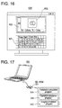
- the model name selected by the operator from the candidates displayed in, e.g., a pull-down menu form is preferably displayed on the operation simulation Web Page screens G20 and G20' (see FIGS. 12 and 13) and the imaging simulation Web Page screens G30 and G30' (see FIGS. 15 and 16).
- the customer can experience in a simulated manner the operation or imaging of the medical image diagnostic device on the operation simulation Web Page screen G20 or the operation simulation Web Page screen G30 displayed on the customer's own terminal (the numerals 11 to 14 of FIG. 1) to intuitively evaluate whether the operativity is good or not.
- FIG. 17 is a block diagram showing a notebook computer 300 and a CD-ROM (Compact Disk - Read Only Memory) 301 according to a third embodiment of the present invention.
- CD-ROM Compact Disk - Read Only Memory
- the CD-ROM 301 records an installation simulation program 31A, an operation simulation program 31B, and an imaging simulation program 31C.
- the installation simulation program 31A describes, in an execution code form of the notebook computer 300, a dimension input step for inputting the dimensions of the installing space of the medical image diagnostic device such as an MRI device, an installing image generation step for generating an installing image when the medical image diagnostic device is installed virtually in the installing space, and an installing image display step for displaying the installing image.
- the notebook computer 300 executes the installation simulation program 31A so as to perform the installation simulation according to the first embodiment in the stand-alone environment.
- the operation simulation program 31B describes, in an execution code form of the notebook computer 300, an operation request reception step for receiving an operation request given on an image simulating an operation part of a medical image diagnostic device or an operation request given through an input device having a function equivalent to that of the operation part, an operation replay image generation step for generating an operation replay image replaying in a simulated manner the operation of the medical image diagnostic device corresponding to the operation request, and an operation replay image display step for displaying the operation replay image.
- the notebook computer 300 executes the operation simulation program 31B so as to perform the operation simulation according to the second embodiment in the stand-alone environment.
- the imaging simulation program 31C describes, in an execution code form of the notebook computer 300, an imaging request reception step for receiving an imaging request given on an image simulating an operation part of a medical image diagnostic device or an imaging request given through an input device having a function equivalent to that of the operation part, and a medical image display step for displaying a medical image obtained when the medical image diagnostic device virtually performs imaging corresponding to the imaging request.
- the notebook computer 300 executes the imaging simulation program 31C so as to perform the imaging simulation according to the second embodiment in the stand-alone environment.
- the notebook computer 300 and the CD-ROM 301 it is possible to perform the installation/operation/imaging simulation of the first and second embodiments in the stand-alone environment. For example, when the sales person in charge goes to the customer for sales activity, the sales person in charge can convincingly present the installability and operativity of the medical image diagnostic device.
- a portable recording medium such as FD (Floppy Disk), MO (Magneto-Optical) disk, DVD (Digital Versatile Disk), or PD (Phase-change Disk) may be used.
- the built-in hard disk of the notebook computer 300 may install the installation/operation/imaging simulation programs 31A, 31B and 31C (in this case, it is unnecessary to read the respective programs from the portable recording medium).
Landscapes
- Engineering & Computer Science (AREA)
- Physics & Mathematics (AREA)
- General Physics & Mathematics (AREA)
- Mathematical Physics (AREA)
- Business, Economics & Management (AREA)
- Medicinal Chemistry (AREA)
- General Health & Medical Sciences (AREA)
- Algebra (AREA)
- Computational Mathematics (AREA)
- Chemical & Material Sciences (AREA)
- Mathematical Analysis (AREA)
- Mathematical Optimization (AREA)
- Health & Medical Sciences (AREA)
- Pure & Applied Mathematics (AREA)
- Medical Informatics (AREA)
- Educational Administration (AREA)
- Educational Technology (AREA)
- Theoretical Computer Science (AREA)
- Measuring And Recording Apparatus For Diagnosis (AREA)
- Management, Administration, Business Operations System, And Electronic Commerce (AREA)
- Medical Treatment And Welfare Office Work (AREA)
- Processing Or Creating Images (AREA)
- Apparatus For Radiation Diagnosis (AREA)
- Magnetic Resonance Imaging Apparatus (AREA)
Abstract
Description
Claims (10)
- An installation simulation method of a medical image diagnostic device comprising the steps of:specifying the dimensions of an installing space of a medical image diagnostic device; andgenerating and displaying an installing image when the medical image diagnostic device is installed virtually in the installing space.
- An operation simulation method of a medical image diagnostic device comprising the step of generating and displaying an operation replay image replaying in a simulated manner the operation of a medical image diagnostic device corresponding to an operation request given on an image simulating an operation part of the medical image diagnostic device or an operation request given through an input device having a function equivalent to that of the operation part.
- An imaging simulation method of a medical image diagnostic device comprising the step of displaying a medical image obtained when imaging of a medical image diagnostic device is performed virtually corresponding to an imaging request given on an image simulating an operation part of the medical image diagnostic device or an imaging request given through an input device having a function equivalent to that of the operation part.
- An installation simulation system of a medical image diagnostic device comprising: a customer side terminal; a host server device; and a network for connecting the customer side terminal to the host server device,
wherein when the dimensions of an installing space of a medical image diagnostic device are specified by an operator, the customer side terminal sends the dimensions of the installing space through the network to the host server device, and
wherein the host server device (or an arithmetic unit connected thereto) generates an installing image when the medical image diagnostic device is installed virtually in the installing space to send the installing image through the network to the customer side terminal, and displays the installing image on the screen of the customer side terminal. - An operation simulation system of a medical image diagnostic device comprising: a customer side terminal; a host server device; and a network for connecting the customer side terminal to the host server device,
wherein the customer side terminal sends, through the network to the host server device, an operation request given on an image simulating an operation part of a medical image diagnostic device or an operation request given through an input device having a function equivalent to that of the operation part, and
wherein the host server device (or an arithmetic unit connected thereto) generates an operation replay image replaying in a simulated manner the operation of a medical image diagnostic device corresponding to the operation request to send the operation replay image through the network to the customer side terminal, and displays the operation replay image on the screen of the customer side terminal. - An imaging simulation system of a medical image diagnostic device comprising: a customer side terminal; a host server device; and a network for connecting the customer side terminal to the host server device,
wherein the customer side terminal sends, through the network to the host server device, an imaging request given on an image simulating an operation part of a medical image diagnostic device or an imaging request given through an input device having a function equivalent to that of the operation part, and
wherein the host server device (or an arithmetic unit connected thereto) sends, through the network to the customer side terminal, a medical image obtained when the medical image diagnostic device virtually performs imaging corresponding to the imaging request to display the medical image on the screen of the customer side terminal. - An installation simulation program of a medical image diagnostic device which describes, in a code form executed by a computer, a dimension input step for inputting the dimensions of an installing space of a medical image diagnostic device, an installing image generation step for generating an installing image when the medical image diagnostic device is installed virtually in the installing space, and an installing image display step for displaying the installing image.
- An operation simulation program of a medical image diagnostic device which describes, in a code form executed by a computer, an operation request reception step for receiving an operation request given on an image simulating an operation part of a medical image diagnostic device or an operation request given through an input device having a function equivalent to that of the operation part, an operation replay image generation step for generating an operation replay image replaying in a simulated manner the operation of a medical image diagnostic device corresponding to the operation request, and an operation replay image display step for displaying the operation replay image.
- An imaging simulation program of a medical image diagnostic device which describes, in a code form executed by a computer, an imaging request reception step for receiving an imaging request given on an image simulating an operation part of a medical image diagnostic device or an imaging request given through an input device having a function equivalent to that of the operation part, and a medical image display step for displaying a medical image obtained when the medical image diagnostic device virtually performs imaging corresponding to the imaging request.
- A recording medium recording at least one of the installation simulation program of claim 7, the operation simulation program of claim 8 and the imaging simulation program of claim 9.
Applications Claiming Priority (2)
| Application Number | Priority Date | Filing Date | Title |
|---|---|---|---|
| JP2000347258A JP4399614B2 (en) | 2000-11-14 | 2000-11-14 | Imaging simulation system for medical diagnostic imaging equipment |
| JP2000347258 | 2000-11-14 |
Publications (2)
| Publication Number | Publication Date |
|---|---|
| EP1205899A2 true EP1205899A2 (en) | 2002-05-15 |
| EP1205899A3 EP1205899A3 (en) | 2004-12-08 |
Family
ID=18821022
Family Applications (1)
| Application Number | Title | Priority Date | Filing Date |
|---|---|---|---|
| EP01309546A Withdrawn EP1205899A3 (en) | 2000-11-14 | 2001-11-13 | Simulation methods and systems for the installation and the operation of a medical image diagnostic device |
Country Status (3)
| Country | Link |
|---|---|
| US (2) | US20020059051A1 (en) |
| EP (1) | EP1205899A3 (en) |
| JP (1) | JP4399614B2 (en) |
Cited By (1)
| Publication number | Priority date | Publication date | Assignee | Title |
|---|---|---|---|---|
| KR20200124108A (en) * | 2019-04-23 | 2020-11-02 | 충남대학교산학협력단 | User compatibility evaluation method for medical device using Virtual Reality |
Families Citing this family (9)
| Publication number | Priority date | Publication date | Assignee | Title |
|---|---|---|---|---|
| JP2005128754A (en) * | 2003-10-23 | 2005-05-19 | Yokogawa Electric Corp | Function addition system |
| US20060174243A1 (en) * | 2005-01-31 | 2006-08-03 | Gregory Brewer | Application software installation prequalification system and method |
| JP5016443B2 (en) * | 2007-10-25 | 2012-09-05 | ティーオーエー株式会社 | Camera installation simulator program |
| US20130167138A1 (en) * | 2009-10-09 | 2013-06-27 | Pradeep Cyril Ekka | Method and apparatus for simulating installations |
| EP2831727B1 (en) * | 2012-03-30 | 2018-09-26 | Intel Corporation | Accessing a device on a remote machine |
| WO2014196342A1 (en) * | 2013-06-06 | 2014-12-11 | 株式会社 日立ハイテクノロジーズ | Specimen pre-processing device system building assistance tool and system information building tool |
| US9792102B2 (en) * | 2015-09-04 | 2017-10-17 | Quest Software Inc. | Identifying issues prior to deploying software |
| JP6894066B2 (en) * | 2015-10-07 | 2021-06-23 | マクエット カルディオプルモナリー ゲーエムベーハー | User interface |
| TWI603316B (en) * | 2016-09-01 | 2017-10-21 | 優派國際股份有限公司 | Method and display device for simulating display characteristics of display |
Family Cites Families (12)
| Publication number | Priority date | Publication date | Assignee | Title |
|---|---|---|---|---|
| US5255207C1 (en) * | 1988-06-16 | 2001-01-09 | Larry Cornwell | Method for designing and detailing cabinets |
| US5882206A (en) * | 1995-03-29 | 1999-03-16 | Gillio; Robert G. | Virtual surgery system |
| US6268862B1 (en) * | 1996-03-08 | 2001-07-31 | Canon Kabushiki Kaisha | Three dimensional virtual space generation by fusing images |
| US6052669A (en) * | 1997-06-06 | 2000-04-18 | Haworth, Inc. | Graphical user interface supporting method and system for remote order generation of furniture products |
| US6391023B1 (en) * | 1998-05-28 | 2002-05-21 | Pearl Technology Holdings, Llc | Thermal radiation facelift device |
| US6490490B1 (en) * | 1998-11-09 | 2002-12-03 | Olympus Optical Co., Ltd. | Remote operation support system and method |
| US6944584B1 (en) * | 1999-04-16 | 2005-09-13 | Brooks Automation, Inc. | System and method for control and simulation |
| JP4164211B2 (en) * | 1999-11-16 | 2008-10-15 | キヤノン株式会社 | Image processing apparatus and method |
| US7263710B1 (en) * | 1999-12-31 | 2007-08-28 | General Electric Company | Medical diagnostic system with on-line real-time video training |
| CA2398823A1 (en) * | 2000-02-14 | 2001-08-23 | First Opinion Corporation | Automated diagnostic system and method |
| US20020064302A1 (en) * | 2000-04-10 | 2002-05-30 | Massengill R. Kemp | Virtual cosmetic autosurgery via telemedicine |
| AU728749B3 (en) * | 2000-11-14 | 2001-01-18 | 1St Share Pty Ltd | Diagnostic imaging simulator |
-
2000
- 2000-11-14 JP JP2000347258A patent/JP4399614B2/en not_active Expired - Fee Related
-
2001
- 2001-09-10 US US09/950,247 patent/US20020059051A1/en not_active Abandoned
- 2001-11-13 EP EP01309546A patent/EP1205899A3/en not_active Withdrawn
-
2007
- 2007-07-25 US US11/880,693 patent/US20080028393A1/en not_active Abandoned
Cited By (1)
| Publication number | Priority date | Publication date | Assignee | Title |
|---|---|---|---|---|
| KR20200124108A (en) * | 2019-04-23 | 2020-11-02 | 충남대학교산학협력단 | User compatibility evaluation method for medical device using Virtual Reality |
Also Published As
| Publication number | Publication date |
|---|---|
| JP4399614B2 (en) | 2010-01-20 |
| JP2002157287A (en) | 2002-05-31 |
| US20020059051A1 (en) | 2002-05-16 |
| EP1205899A3 (en) | 2004-12-08 |
| US20080028393A1 (en) | 2008-01-31 |
Similar Documents
| Publication | Publication Date | Title |
|---|---|---|
| US20080028393A1 (en) | Simulated installation and operation of a diagnostic imaging device at a remote location | |
| US7403220B2 (en) | Apparatus, methods, and systems for viewing and manipulating a virtual environment | |
| JP4208791B2 (en) | Image processing apparatus, control method therefor, and program | |
| US7420575B2 (en) | Image processing apparatus, image processing method and image processing program | |
| JPWO2003043501A1 (en) | Ultrasonic diagnostic apparatus, workflow editing system, and control method of ultrasonic diagnostic apparatus | |
| JP2001057700A (en) | Method and system for sound projection for computer display | |
| JP2003310592A (en) | Remote X-ray imaging method, remote X-ray imaging system, simulation method for medical image diagnostic apparatus, information processing service method, and modality simulator system | |
| WO2008078890A1 (en) | Intelligent robot controlling simulation system | |
| US20060132508A1 (en) | Multi-planar image viewing system and method | |
| Coffey et al. | Visualizing motion data in virtual reality: Understanding the roles of animation, interaction, and static presentation | |
| US7786990B2 (en) | Cursor mode display system and method | |
| Kensek et al. | Augmented reality: An application for architecture | |
| He et al. | AdapTUI: Adaptation of Geometric-Feature-Based Tangible User Interfaces in Augmented Reality | |
| US20060198613A1 (en) | Gymnastic guide system displayed in a computer | |
| JP5054059B2 (en) | Operation simulation method, system and storage medium for medical image diagnostic apparatus | |
| JP2009238228A (en) | Method, system, program for installation simulation of medical image diagnostic device, and storage medium | |
| US7689389B1 (en) | System and method for synchronizing and using a three dimensional view with a block diagram model | |
| Horii | Electronic imaging workstations: ergonomic issues and the user interface. | |
| EP3893245A1 (en) | Correction of automated label data for tomographic medical imaging systems | |
| Seifert et al. | MEDIFRAME–an extendable software framework for medical applications | |
| US6826436B1 (en) | Method and apparatus for graphing motion of computer aided design (CAD) geometry | |
| WO2024123947A1 (en) | Systems, methods and apparatus for points-based registration of a medical hologram to a surgical site in holographic medical augmented reality | |
| Gur et al. | Requirements for PACS: users' perspective. | |
| JP4776901B2 (en) | Image processing apparatus, control method therefor, and program | |
| Cleary et al. | Simulator/planner for CT-directed needle biopsy of the spine |
Legal Events
| Date | Code | Title | Description |
|---|---|---|---|
| PUAI | Public reference made under article 153(3) epc to a published international application that has entered the european phase |
Free format text: ORIGINAL CODE: 0009012 |
|
| AK | Designated contracting states |
Kind code of ref document: A2 Designated state(s): AT BE CH CY DE DK ES FI FR GB GR IE IT LI LU MC NL PT SE TR |
|
| AX | Request for extension of the european patent |
Free format text: AL;LT;LV;MK;RO;SI |
|
| RIC1 | Information provided on ipc code assigned before grant |
Ipc: 7G 09B 9/00 B Ipc: 7G 09B 23/28 B Ipc: 7G 06F 17/60 A |
|
| PUAL | Search report despatched |
Free format text: ORIGINAL CODE: 0009013 |
|
| AK | Designated contracting states |
Kind code of ref document: A3 Designated state(s): AT BE CH CY DE DK ES FI FR GB GR IE IT LI LU MC NL PT SE TR |
|
| AX | Request for extension of the european patent |
Extension state: AL LT LV MK RO SI |
|
| 17P | Request for examination filed |
Effective date: 20050608 |
|
| AKX | Designation fees paid |
Designated state(s): DE FR GB |
|
| STAA | Information on the status of an ep patent application or granted ep patent |
Free format text: STATUS: THE APPLICATION IS DEEMED TO BE WITHDRAWN |
|
| 18D | Application deemed to be withdrawn |
Effective date: 20110601 |