EP1205782A2 - Optisch abstimmbarer mikroelektromechanischer Fabry-Perot Resonator - Google Patents
Optisch abstimmbarer mikroelektromechanischer Fabry-Perot Resonator Download PDFInfo
- Publication number
- EP1205782A2 EP1205782A2 EP01114653A EP01114653A EP1205782A2 EP 1205782 A2 EP1205782 A2 EP 1205782A2 EP 01114653 A EP01114653 A EP 01114653A EP 01114653 A EP01114653 A EP 01114653A EP 1205782 A2 EP1205782 A2 EP 1205782A2
- Authority
- EP
- European Patent Office
- Prior art keywords
- wavelength
- tuning
- light signal
- resonator
- mirror
- Prior art date
- Legal status (The legal status is an assumption and is not a legal conclusion. Google has not performed a legal analysis and makes no representation as to the accuracy of the status listed.)
- Withdrawn
Links
- 230000004044 response Effects 0.000 claims abstract description 51
- 230000003287 optical effect Effects 0.000 claims abstract description 34
- 238000012544 monitoring process Methods 0.000 claims abstract description 5
- 238000000034 method Methods 0.000 claims description 13
- 230000008859 change Effects 0.000 claims description 3
- 230000008569 process Effects 0.000 claims description 3
- 230000000903 blocking effect Effects 0.000 claims 2
- 230000005855 radiation Effects 0.000 description 33
- 230000007423 decrease Effects 0.000 description 8
- 239000000758 substrate Substances 0.000 description 6
- 238000000926 separation method Methods 0.000 description 5
- 238000010586 diagram Methods 0.000 description 4
- 230000000284 resting effect Effects 0.000 description 4
- 230000000694 effects Effects 0.000 description 3
- 239000004065 semiconductor Substances 0.000 description 3
- 230000010355 oscillation Effects 0.000 description 2
- 230000009467 reduction Effects 0.000 description 2
- 230000003321 amplification Effects 0.000 description 1
- 238000013459 approach Methods 0.000 description 1
- 230000035559 beat frequency Effects 0.000 description 1
- 230000008901 benefit Effects 0.000 description 1
- 238000011088 calibration curve Methods 0.000 description 1
- 238000004891 communication Methods 0.000 description 1
- 238000010276 construction Methods 0.000 description 1
- 230000001419 dependent effect Effects 0.000 description 1
- 238000003754 machining Methods 0.000 description 1
- 238000012986 modification Methods 0.000 description 1
- 230000004048 modification Effects 0.000 description 1
- 238000003199 nucleic acid amplification method Methods 0.000 description 1
- 239000012780 transparent material Substances 0.000 description 1
Images

Classifications
-
- G—PHYSICS
- G02—OPTICS
- G02B—OPTICAL ELEMENTS, SYSTEMS OR APPARATUS
- G02B6/00—Light guides; Structural details of arrangements comprising light guides and other optical elements, e.g. couplings
- G02B6/24—Coupling light guides
- G02B6/26—Optical coupling means
- G02B6/28—Optical coupling means having data bus means, i.e. plural waveguides interconnected and providing an inherently bidirectional system by mixing and splitting signals
- G02B6/293—Optical coupling means having data bus means, i.e. plural waveguides interconnected and providing an inherently bidirectional system by mixing and splitting signals with wavelength selective means
- G02B6/29346—Optical coupling means having data bus means, i.e. plural waveguides interconnected and providing an inherently bidirectional system by mixing and splitting signals with wavelength selective means operating by wave or beam interference
- G02B6/29358—Multiple beam interferometer external to a light guide, e.g. Fabry-Pérot, etalon, VIPA plate, OTDL plate, continuous interferometer, parallel plate resonator
-
- G—PHYSICS
- G01—MEASURING; TESTING
- G01J—MEASUREMENT OF INTENSITY, VELOCITY, SPECTRAL CONTENT, POLARISATION, PHASE OR PULSE CHARACTERISTICS OF INFRARED, VISIBLE OR ULTRAVIOLET LIGHT; COLORIMETRY; RADIATION PYROMETRY
- G01J3/00—Spectrometry; Spectrophotometry; Monochromators; Measuring colours
- G01J3/12—Generating the spectrum; Monochromators
- G01J3/26—Generating the spectrum; Monochromators using multiple reflection, e.g. Fabry-Perot interferometer, variable interference filters
-
- G—PHYSICS
- G02—OPTICS
- G02B—OPTICAL ELEMENTS, SYSTEMS OR APPARATUS
- G02B26/00—Optical devices or arrangements for the control of light using movable or deformable optical elements
- G02B26/001—Optical devices or arrangements for the control of light using movable or deformable optical elements based on interference in an adjustable optical cavity
-
- G—PHYSICS
- G02—OPTICS
- G02B—OPTICAL ELEMENTS, SYSTEMS OR APPARATUS
- G02B26/00—Optical devices or arrangements for the control of light using movable or deformable optical elements
- G02B26/02—Optical devices or arrangements for the control of light using movable or deformable optical elements for controlling the intensity of light
-
- G—PHYSICS
- G02—OPTICS
- G02B—OPTICAL ELEMENTS, SYSTEMS OR APPARATUS
- G02B6/00—Light guides; Structural details of arrangements comprising light guides and other optical elements, e.g. couplings
- G02B6/24—Coupling light guides
- G02B6/26—Optical coupling means
- G02B6/28—Optical coupling means having data bus means, i.e. plural waveguides interconnected and providing an inherently bidirectional system by mixing and splitting signals
- G02B6/293—Optical coupling means having data bus means, i.e. plural waveguides interconnected and providing an inherently bidirectional system by mixing and splitting signals with wavelength selective means
- G02B6/29379—Optical coupling means having data bus means, i.e. plural waveguides interconnected and providing an inherently bidirectional system by mixing and splitting signals with wavelength selective means characterised by the function or use of the complete device
- G02B6/29395—Optical coupling means having data bus means, i.e. plural waveguides interconnected and providing an inherently bidirectional system by mixing and splitting signals with wavelength selective means characterised by the function or use of the complete device configurable, e.g. tunable or reconfigurable
Definitions
- the present invention relates to optical filters, and more particularly, to tunable Fabry-Perot optical resonators, filters and lasers constructed therefrom.
- Tunable optical resonators are utilized in optical communication systems and in the construction of lasers.
- Optical filters and lasers based on Fabry-Perot resonators can be constructed using microelectromechanical machining (MEM) techniques, and hence, can, in principle, provide an economically attractive tunable filter or tunable laser.
- MEM microelectromechanical machining
- a Fabry-Perot resonator cavity is formed between two mirrors. One of these mirrors is flat and located on a semiconductor substrate. The other mirror may be curved and is suspended on a number of micro-mechanical cantilevers.
- a tuning voltage between the cantilevers and the substrate causes the suspended mirror to move towards the fixed mirror on the substrate, thereby reducing the spacing between the two mirrors of the Fabry-Perot resonator. Since the filter's bandpass frequency is determined by the mirror spacing, a reduction in spacing between the two mirrors causes the resonant optical frequency of the cavity to increase. The shift in the resonant frequency enables the device to be used directly as a tunable bandpass filter. If an optically-pumped or electrically-pumped optical gain medium (active region) is placed in the cavity, the device becomes a tunable laser, with the lasing wavelength controlled by the resonant frequency of the Fabry-Perot cavity.
- the filter must be provided with an electrical power source and feedback circuitry to provide the correct tuning voltage.
- the tuning voltages are typically in the range of tens of volts. Such voltage levels are outside the usual control voltages on standard integrated circuits, and hence, the inclusion of this non-optical circuitry increases the cost and complexity of the devices.
- the present invention is a tunable optical resonator whose resonance frequency is determined by a light signal introduced into the resonator.
- the resonator includes an optical cavity having a first mirror and a second mirror. The first mirror and second mirror are supported relative to one another such that the distance between the first and second mirrors may be altered by applying a force to said second mirror thereby altering the resonance frequency of said cavity.
- the resonator includes a light input port for receiving a tuning light signal, and an optional light signal generator for generating the tuning light source. The tuning light signal is introduced into the optical cavity such that the tuning light signal is reflected between the first and second mirrors.
- the resonator In the absence of the tuning light signal, the resonator has a resonance characterized by a resonance response curve centered at ⁇ 0 .
- the tuning light signal has a wavelength ⁇ 1 within said resonance response curve and sufficient power to cause said resonance response curve to shift such that the resonance response curve is now centered at ⁇ 2 , where ⁇ 2 > ⁇ 1 .
- a circuit for monitoring the light leaving the resonator is utilized to control the wavelength and/or amplitude of the tuning light signal such that the light leaving the resonator has a predetermined wavelength.
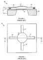
- Figure 1 is a top view of a prior art Fabry-Perot based filter or laser.
- Figure 2 is a cross-sectional view of the laser shown in Figure 1 through line 11-12.
- a Fabry-Perot resonator cavity is formed between mirrors 13 and 14.
- Mirror 14 is flat and located on a semiconductor substrate 25.
- the mirror 13 is typically curved and is suspended on a number of micro-mechanical cantilevers shown at 15-18.
- the mirrors are preferably constructed from a number of layers of transparent material having indices of refraction that alternate from layer to layer. Such mirrors are well known to the art of semiconductor lasers, and hence, will not be discussed in detail here. To simplify the drawing, the layered structure of the mirrors has been omitted.
- the application of a tuning voltage via a voltage source between the cantilevers and the substrate causes suspended mirror 13 to move towards mirror 14, thereby reducing the spacing between the two mirrors of the Fabry-Perot cavity. Since the resonant frequency of the cavity is determined by the distance between the mirrors, this reduction in spacing between the two mirrors causes the resonant optical frequency of the cavity to increase. The shift in the resonant frequency enables the device to be used directly as a tunable bandpass filter. If an optically-pumped or electrically-pumped optical gain medium 20 is placed in the cavity, the device becomes a tunable laser, with the lasing wavelength controlled by the resonant frequency of the Fabry-Perot cavity.
- the present invention is based on the observation that prior art devices of the type shown in Figures 1 and 2 suffer from an undesirable wavelength-dependent tuning voltage. That is, the tuning voltage needed to set the resonance wavelength at any given value depends on the optical power density in the cavity for power densities above some predetermined value that depends on the physical characteristics of the device. This shift in tuning voltage is the result of the radiation pressure in the cavity. The radiation force tends to push the moving mirror in the Fabry-Perot cavity away from the fixed mirror. Thus, the radiation force tends to tune the filter or laser to longer wavelengths. The magnitude of the radiation force is proportional to the internal optical power in the cavity, which is proportional to the optical output power from the filter.
- the moveable mirror As the radiation force pushes the moveable mirror away from the fixed mirror, it also pushes the moving mirror against the spring forces generated by the cantilever arms 15-18 discussed above. When the increase in spring force matches the radiation force, the moveable mirror will stop moving and the filter or laser will exhibit a new resonant wavelength.
- the present invention utilizes this effect to tune the resonant wavelength optically.
- the resonant wavelength of the cavity can be altered.
- the finesse gives a measure of the number of times a photon is reflected back and forth.
- Fabry Perot resonators having a finesse of greater than 1000 are readily constructed using MEM techniques.
- the radiation pressure generated by a tuning signal is, in effect, amplified by a factor that is proportional to the finesse of the cavity. This amplification factor allows a relatively weak tuning signal to shift the resonant wavelength of the cavity by a large amount.
- the wavelength of the tuning signal sets the resonant wavelength of the cavity to within an error that depends on the width of the cavity resonance.
- the power in the tuning signal can then be used to fine tune the resonance frequency.
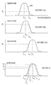
- FIG 3(A) illustrates the initial position of the filter response curve 100 and the relationship of the tuning wavelength to the resting wavelength ⁇ 0 .
- ⁇ 0 ⁇ ⁇ T the relationship of the tuning wavelength to the resting wavelength ⁇ 0 .
- F 0 the force on the moveable mirror.
- F 0 will depend on the finesse of the cavity and the power level in the tuning signal.
- the radiation force F 0 causes the mirrors to move apart, and hence, the filter response curve shifts to a new location characterized by a new resonant wavelength ⁇ N as shown in Figure 3(B).
- the shift in the resonance response of the cavity increases the radiation force applied to the mirrors to a new value F 1 , since the tuning wavelength is now closer to the center of the resonance response curve.
- the power in the tuning signal is chosen such that ⁇ N > ⁇ T , i.e., the configuration shown in Figure 3(C).
- the reason this configuration is preferred lies in the stability of the mirror setting in the face of thermal noise.
- the moveable mirror is also subjected to thermal fluctuations that cause the mirror to vibrate about the position set by the tuning light signal and the spring restoration forces. These vibrations result in small oscillations in the center frequency of the filter response or laser. These oscillations, in turn, introduce amplitude fluctuations in the filtered light or laser light signal. Hence, an arrangement in which these noise fluctuations are reduced is preferred.
- thermal noise causes the moveable mirror to be displaced slightly closer to the fixed mirror.
- the resonance response curve will shift to slightly shorter wavelengths, and the radiation force will increase.
- the increased radiation force will cause the mirrors to move further apart, i.e., the radiation force will counter the force induced by the thermal noise.
- the thermal noise force acts in a direction that causes the mirrors to move further apart.
- the filter response curve will then be shifted to a longer wavelength. This will result in a decrease in the radiation force.
- the decrease in force will, in turn, cause the mirrors to move closer together under the influence of the spring restoration force applied by the cantilever arms.
- the change in the radiation force acts to counter the force induced by the thermal noise.
- the radiation force amplifies the thermal noise forces, and hence, increases the thermal noise in the light signals processed by the filter.
- the thermal noise force causes the mirrors to move apart, the resonance response curve will shift to longer wavelengths, and the radiation force will also increase. The increased radiation force will cause the mirrors to move still further apart. Hence, the radiation force will amplify the thermal noise.
- the thermal noise causes the mirrors to move closer together, the resonance response curve will shift to lower wavelengths, and the radiation force will decrease causing a further shift to lower wavelengths.
- the thermal noise is amplified.
- the tuning wavelength was close to the resting wavelength in the sense that both wavelengths were within the resonance response curve of the filter.
- the resonance was then shifted to a new value that was determined by the tuning wavelength and the power level of the tuning source.
- the amount by which the resonance wavelength can be tuned using this approach is determined by the width of the resonance response curve for a fixed tuning wavelength.
- a much greater tuning range can be achieved by shifting the wavelength of the tuning light signal.
- the tuning light signal has shifted the resonance wavelength to ⁇ N and ⁇ N > ⁇ T as shown in Figure 4.
- the tuning wavelength is increased to a new tuning wavelength ⁇ ' T .
- the radiation force will increase from F 2 to F 3 .
- the increase in radiation force will cause the mirrors to move further apart until the new force is balanced by the spring restoration force.
- the radiation force also decreases to F 4 as the filter response curve moves to higher wavelengths.
- the new filter response curve shown in broken lines, will be located at a center wavelength ⁇ ' N > ⁇ ' T > ⁇ N .
- the center frequency of the resonance response can be moved still further.
- the distance the mirrors can be moved by shifting the tuning wavelength is determined by the maximum radiation force and the spring constants of the cantilever arms. For a fixed power in the tuning light signal, each time the wavelength is increased, the center wavelength of the resonance response curve moves closer to that of the tuning light signal when the mirror distance stabilizes. When the two wavelengths become the same, the maximum tuning for the current power level will have been achieved. Once this point has been reached, any further increase in the tuning wavelength will result in a decrease in the radiation force. The decrease in radiation force will result in the filter response curve shifting back to shorter wavelengths, which, in turn, will further reduce the radiation force. This shift will continue until the response curve shifts to a wavelength at which the tuning wavelength is no longer within the response curve, i.e., the radiation will then be zero. The spring restoration forces will then return the mirrors to their resting configuration, i.e., the center wavelength of the filter response curve will return to ⁇ 0 .
- the wavelength of the tuning signal sets the center wavelength of the resonance response curve of the Fabry Perot filter.
- the exact position of the center frequency of the response curve relative to the tuning signal wavelength and power cannot be accurately predicted theoretically; however, the relationship can be measured for several values of the tuning signal wavelength and power. Then, measured values can be used to generate the appropriate calibration curves.
- the position of the resonance response curve can be fine-tuned by adjusting the power level of the tuning signal while leaving the wavelength fixed.
- the tuning signal power level is initially set such that the center wavelength of the response curve is longer than the wavelength of the tuning signal, i.e., the case shown in Figure 3(C). If the power level of the tuning signal is increased, the mirror separation will increase, and the response curve will be shifted to longer wavelengths. This shift will reduce the radiation force, since the tuning signal wavelength will now be further from the center of the response curve. Hence, when the system stabilizes, the center wavelength of the response curve will have increased by an amount that is a small fraction of the width of the response curve.
- the mirror separation will decrease, and the center frequency of the response curve will shift to shorter wavelengths.
- the radiation force will then increase because the tuning signal wavelength will now be closer to the center frequency of the response curve. This will partially counter the shift in the response curve.
- the center wavelength of the response curve will have been reduced by a small fraction of the width of the response curve.
- the tuning wavelength is chosen to be different from the wavelength at which the Fabry Perot resonator is to operate in either a filter or a laser mode.
- the tuning source can utilize a resonance at a first value of N to control the resonance about a wavelength at a different value of N.
- the tuning light signal can then be removed from the output light signal with the aid of a band-blocking filter that blocks the tuning light signal but not the signal of interest.
- Such an embodiment of the present invention is shown at 300 in Figure 5, which is a block diagram of a tunable filter according to the present invention.
- the input light signal at ⁇ 2 is combined with the light signal at wavelength ⁇ 1 from a tunable source 302 by an optical coupler 304.
- the combined signal is applied to Fabry Perot resonator 306.
- the output of Fabry Perot resonator 306 is then passed through an optical filter 308 that blocks light at ⁇ 1 but passes light at ⁇ 2 .
- FIG. 6 is block diagram of an embodiment of a tunable filter 400 according to the present invention in which the power level of the tuning signal is also adjusted to provide fine tuning of the resonance wavelength of resonator 306.
- Tunable filter 400 samples the output of filter 308 via coupler 402. The sampled light signal is compared to a calibration light signal having a wavelength of ⁇ 3 by a control circuit 403. Controller 403 generates an amplitude control signal that sets the amplitude of the output of light source 302 such that the output of filter 308 is brought closer to the desired wavelength.
- controller 403 may also generate the wavelength control signal for light source 302 based on the input calibration signal. It should also be noted that the calibration signal can be the output of light source 302 obtained from the unused port of coupler 304. In this case, controller 403 adjusts the amplitude to maintain the resonator center wavelength at a fixed difference from the wavelength of the tunable light source.
- Optical comparators suitable for use in controller 403 are known to the optical arts, and hence, will not be discussed in detail here. It is sufficient to note that an optical mixer for combining the calibration light signal with the sampled output light signal and a detector for measuring the resulting beat frequency can be utilized if the difference in wavelengths is not large.
- a filter system according to the present invention does not require a power source at the Fabry Perot resonator to control the wavelength of the resonance. This allows the present invention to control a filter or laser that is in a remote location lacking power and having a markedly different temperature environment then that of the controller 403 or light source 302.
- prior art MEM Fabry Perot resonators when designed even for a fixed frequency must include some form of feedback circuit for precisely setting and holding the resonant frequency at the desired value.
- the variations in the MEM process from device to device across a wafer will cause small variations in the resonance frequency.
- the mirrors must be set with the applied tuning voltage by comparing the output light wavelength with that of a standard light source at the desired resonant wavelength or a multiple thereof.
- a feedback system must constantly adjust the applied voltage to compensate for other factors that change the mirror distance such as temperature changes.
- the present invention even with feedback controller 403 and light source 302, is no more expensive than conventional MEM Fabry Perot resonators.
Applications Claiming Priority (2)
| Application Number | Priority Date | Filing Date | Title |
|---|---|---|---|
| US704004 | 2000-11-01 | ||
| US09/704,004 US6714565B1 (en) | 2000-11-01 | 2000-11-01 | Optically tunable Fabry Perot microelectromechanical resonator |
Publications (2)
| Publication Number | Publication Date |
|---|---|
| EP1205782A2 true EP1205782A2 (de) | 2002-05-15 |
| EP1205782A3 EP1205782A3 (de) | 2002-05-29 |
Family
ID=24827674
Family Applications (1)
| Application Number | Title | Priority Date | Filing Date |
|---|---|---|---|
| EP01114653A Withdrawn EP1205782A3 (de) | 2000-11-01 | 2001-06-19 | Optisch abstimmbarer mikroelektromechanischer Fabry-Perot Resonator |
Country Status (3)
| Country | Link |
|---|---|
| US (1) | US6714565B1 (de) |
| EP (1) | EP1205782A3 (de) |
| JP (1) | JP2002207180A (de) |
Cited By (15)
| Publication number | Priority date | Publication date | Assignee | Title |
|---|---|---|---|---|
| EP1640779A2 (de) * | 2004-09-27 | 2006-03-29 | Idc, Llc | Verfahren und Vorrichtung für Reflexionsvermögen mit einer vorbestimmten spektralen Antwort |
| US8004743B2 (en) | 2006-04-21 | 2011-08-23 | Qualcomm Mems Technologies, Inc. | Method and apparatus for providing brightness control in an interferometric modulator (IMOD) display |
| US8098431B2 (en) | 2004-09-27 | 2012-01-17 | Qualcomm Mems Technologies, Inc. | Method and device for generating white in an interferometric modulator display |
| US8102407B2 (en) | 2004-09-27 | 2012-01-24 | Qualcomm Mems Technologies, Inc. | Method and device for manipulating color in a display |
| US8243360B2 (en) | 2004-09-27 | 2012-08-14 | Qualcomm Mems Technologies, Inc. | Device having a conductive light absorbing mask and method for fabricating same |
| US8390547B2 (en) | 2004-09-27 | 2013-03-05 | Qualcomm Mems Technologies, Inc. | Conductive bus structure for interferometric modulator array |
| US8488228B2 (en) | 2009-09-28 | 2013-07-16 | Qualcomm Mems Technologies, Inc. | Interferometric display with interferometric reflector |
| US8736949B2 (en) | 2007-07-31 | 2014-05-27 | Qualcomm Mems Technologies, Inc. | Devices and methods for enhancing color shift of interferometric modulators |
| US8736939B2 (en) | 2011-11-04 | 2014-05-27 | Qualcomm Mems Technologies, Inc. | Matching layer thin-films for an electromechanical systems reflective display device |
| US8797628B2 (en) | 2007-10-19 | 2014-08-05 | Qualcomm Memstechnologies, Inc. | Display with integrated photovoltaic device |
| US8848294B2 (en) | 2010-05-20 | 2014-09-30 | Qualcomm Mems Technologies, Inc. | Method and structure capable of changing color saturation |
| US8941631B2 (en) | 2007-11-16 | 2015-01-27 | Qualcomm Mems Technologies, Inc. | Simultaneous light collection and illumination on an active display |
| US8971675B2 (en) | 2006-01-13 | 2015-03-03 | Qualcomm Mems Technologies, Inc. | Interconnect structure for MEMS device |
| US8979349B2 (en) | 2009-05-29 | 2015-03-17 | Qualcomm Mems Technologies, Inc. | Illumination devices and methods of fabrication thereof |
| US9057872B2 (en) | 2010-08-31 | 2015-06-16 | Qualcomm Mems Technologies, Inc. | Dielectric enhanced mirror for IMOD display |
Families Citing this family (34)
| Publication number | Priority date | Publication date | Assignee | Title |
|---|---|---|---|---|
| US6674562B1 (en) | 1994-05-05 | 2004-01-06 | Iridigm Display Corporation | Interferometric modulation of radiation |
| US7898521B2 (en) | 2004-09-27 | 2011-03-01 | Qualcomm Mems Technologies, Inc. | Device and method for wavelength filtering |
| US7630119B2 (en) | 2004-09-27 | 2009-12-08 | Qualcomm Mems Technologies, Inc. | Apparatus and method for reducing slippage between structures in an interferometric modulator |
| US7911428B2 (en) | 2004-09-27 | 2011-03-22 | Qualcomm Mems Technologies, Inc. | Method and device for manipulating color in a display |
| US7527995B2 (en) | 2004-09-27 | 2009-05-05 | Qualcomm Mems Technologies, Inc. | Method of making prestructure for MEMS systems |
| US7564612B2 (en) | 2004-09-27 | 2009-07-21 | Idc, Llc | Photonic MEMS and structures |
| US8008736B2 (en) | 2004-09-27 | 2011-08-30 | Qualcomm Mems Technologies, Inc. | Analog interferometric modulator device |
| US8031133B2 (en) | 2004-09-27 | 2011-10-04 | Qualcomm Mems Technologies, Inc. | Method and device for manipulating color in a display |
| US7710632B2 (en) | 2004-09-27 | 2010-05-04 | Qualcomm Mems Technologies, Inc. | Display device having an array of spatial light modulators with integrated color filters |
| US7372613B2 (en) | 2004-09-27 | 2008-05-13 | Idc, Llc | Method and device for multistate interferometric light modulation |
| US7944599B2 (en) | 2004-09-27 | 2011-05-17 | Qualcomm Mems Technologies, Inc. | Electromechanical device with optical function separated from mechanical and electrical function |
| US8362987B2 (en) | 2004-09-27 | 2013-01-29 | Qualcomm Mems Technologies, Inc. | Method and device for manipulating color in a display |
| US7304784B2 (en) | 2004-09-27 | 2007-12-04 | Idc, Llc | Reflective display device having viewable display on both sides |
| US7649671B2 (en) | 2006-06-01 | 2010-01-19 | Qualcomm Mems Technologies, Inc. | Analog interferometric modulator device with electrostatic actuation and release |
| US7527998B2 (en) | 2006-06-30 | 2009-05-05 | Qualcomm Mems Technologies, Inc. | Method of manufacturing MEMS devices providing air gap control |
| US8115987B2 (en) | 2007-02-01 | 2012-02-14 | Qualcomm Mems Technologies, Inc. | Modulating the intensity of light from an interferometric reflector |
| US7643202B2 (en) | 2007-05-09 | 2010-01-05 | Qualcomm Mems Technologies, Inc. | Microelectromechanical system having a dielectric movable membrane and a mirror |
| US7630121B2 (en) | 2007-07-02 | 2009-12-08 | Qualcomm Mems Technologies, Inc. | Electromechanical device with optical function separated from mechanical and electrical function |
| US8058549B2 (en) | 2007-10-19 | 2011-11-15 | Qualcomm Mems Technologies, Inc. | Photovoltaic devices with integrated color interferometric film stacks |
| CN101836137A (zh) | 2007-10-23 | 2010-09-15 | 高通Mems科技公司 | 基于微机电系统的可调整透射装置 |
| US8164821B2 (en) | 2008-02-22 | 2012-04-24 | Qualcomm Mems Technologies, Inc. | Microelectromechanical device with thermal expansion balancing layer or stiffening layer |
| US7944604B2 (en) | 2008-03-07 | 2011-05-17 | Qualcomm Mems Technologies, Inc. | Interferometric modulator in transmission mode |
| US7612933B2 (en) | 2008-03-27 | 2009-11-03 | Qualcomm Mems Technologies, Inc. | Microelectromechanical device with spacing layer |
| US8023167B2 (en) | 2008-06-25 | 2011-09-20 | Qualcomm Mems Technologies, Inc. | Backlight displays |
| US8358266B2 (en) | 2008-09-02 | 2013-01-22 | Qualcomm Mems Technologies, Inc. | Light turning device with prismatic light turning features |
| WO2010096706A2 (en) * | 2009-02-19 | 2010-08-26 | Cornell University | Optomechanical non-reciprocal device |
| US8270056B2 (en) | 2009-03-23 | 2012-09-18 | Qualcomm Mems Technologies, Inc. | Display device with openings between sub-pixels and method of making same |
| US8270062B2 (en) | 2009-09-17 | 2012-09-18 | Qualcomm Mems Technologies, Inc. | Display device with at least one movable stop element |
| KR20130100232A (ko) | 2010-04-09 | 2013-09-10 | 퀄컴 엠이엠에스 테크놀로지스, 인크. | 전기 기계 디바이스의 기계층 및 그 형성 방법 |
| KR20130091763A (ko) | 2010-08-17 | 2013-08-19 | 퀄컴 엠이엠에스 테크놀로지스, 인크. | 간섭 디스플레이 장치에서의 전하 중성 전극의 작동 및 교정 |
| US9134527B2 (en) | 2011-04-04 | 2015-09-15 | Qualcomm Mems Technologies, Inc. | Pixel via and methods of forming the same |
| US8963159B2 (en) | 2011-04-04 | 2015-02-24 | Qualcomm Mems Technologies, Inc. | Pixel via and methods of forming the same |
| US8659816B2 (en) | 2011-04-25 | 2014-02-25 | Qualcomm Mems Technologies, Inc. | Mechanical layer and methods of making the same |
| US9212990B1 (en) | 2011-12-06 | 2015-12-15 | Zybertec Llc | System and methods for molecular detection using intracavity laser absorption spectroscopy |
Citations (5)
| Publication number | Priority date | Publication date | Assignee | Title |
|---|---|---|---|---|
| EP0298598A2 (de) * | 1987-06-09 | 1989-01-11 | AT&T Corp. | Optisches Übertragungssystem mit Konstanthalten einer Frequenzgruppe |
| US5280173A (en) * | 1992-01-31 | 1994-01-18 | Brown University Research Foundation | Electric and electromagnetic field sensing system including an optical transducer |
| EP0608611A1 (de) * | 1993-01-23 | 1994-08-03 | Nortel Networks Corporation | Optische Solitonpulsenübertragungssystem |
| US5401956A (en) * | 1993-09-29 | 1995-03-28 | United Technologies Corporation | Diagnostic system for fiber grating sensors |
| WO1998005995A1 (en) * | 1996-08-04 | 1998-02-12 | Eost Ltd. | Ultra-fast tunable optical filters |
Family Cites Families (4)
| Publication number | Priority date | Publication date | Assignee | Title |
|---|---|---|---|---|
| US3639775A (en) * | 1970-08-03 | 1972-02-01 | Bell Telephone Labor Inc | Acoustically controlled optical devices |
| JPH0675144B2 (ja) * | 1989-01-12 | 1994-09-21 | 松下電器産業株式会社 | 光変調波復調装置 |
| ES2096109T3 (es) * | 1991-05-31 | 1997-03-01 | Alcatel Nv | Laser semiconductor controlado opticamente. |
| US5457707A (en) * | 1993-08-24 | 1995-10-10 | Spectra-Physics Lasers, Inc. | Master optical parametric oscillator/power optical parametric oscillator |
-
2000
- 2000-11-01 US US09/704,004 patent/US6714565B1/en not_active Expired - Fee Related
-
2001
- 2001-06-19 EP EP01114653A patent/EP1205782A3/de not_active Withdrawn
- 2001-10-31 JP JP2001334181A patent/JP2002207180A/ja active Pending
Patent Citations (5)
| Publication number | Priority date | Publication date | Assignee | Title |
|---|---|---|---|---|
| EP0298598A2 (de) * | 1987-06-09 | 1989-01-11 | AT&T Corp. | Optisches Übertragungssystem mit Konstanthalten einer Frequenzgruppe |
| US5280173A (en) * | 1992-01-31 | 1994-01-18 | Brown University Research Foundation | Electric and electromagnetic field sensing system including an optical transducer |
| EP0608611A1 (de) * | 1993-01-23 | 1994-08-03 | Nortel Networks Corporation | Optische Solitonpulsenübertragungssystem |
| US5401956A (en) * | 1993-09-29 | 1995-03-28 | United Technologies Corporation | Diagnostic system for fiber grating sensors |
| WO1998005995A1 (en) * | 1996-08-04 | 1998-02-12 | Eost Ltd. | Ultra-fast tunable optical filters |
Non-Patent Citations (1)
| Title |
|---|
| SZYMANIEC K ET AL: "Injection locking of diode lasers to frequency modulated source" OPTICS COMMUNICATIONS, NORTH-HOLLAND PUBLISHING CO. AMSTERDAM, NL, vol. 144, no. 1-3, 1 December 1997 (1997-12-01), pages 50-54, XP004097931 ISSN: 0030-4018 * |
Cited By (21)
| Publication number | Priority date | Publication date | Assignee | Title |
|---|---|---|---|---|
| KR101227621B1 (ko) * | 2004-09-27 | 2013-01-31 | 퀄컴 엠이엠에스 테크놀로지스, 인크. | 소정의 스펙트럼 응답을 갖는 반사를 위한 방법 및 기기 |
| US9097885B2 (en) | 2004-09-27 | 2015-08-04 | Qualcomm Mems Technologies, Inc. | Device having a conductive light absorbing mask and method for fabricating same |
| EP1640779A2 (de) * | 2004-09-27 | 2006-03-29 | Idc, Llc | Verfahren und Vorrichtung für Reflexionsvermögen mit einer vorbestimmten spektralen Antwort |
| US8098431B2 (en) | 2004-09-27 | 2012-01-17 | Qualcomm Mems Technologies, Inc. | Method and device for generating white in an interferometric modulator display |
| US8102407B2 (en) | 2004-09-27 | 2012-01-24 | Qualcomm Mems Technologies, Inc. | Method and device for manipulating color in a display |
| US8243360B2 (en) | 2004-09-27 | 2012-08-14 | Qualcomm Mems Technologies, Inc. | Device having a conductive light absorbing mask and method for fabricating same |
| EP1640779A3 (de) * | 2004-09-27 | 2009-05-13 | Idc, Llc | Verfahren und Vorrichtung für Reflexionsvermögen mit einer vorbestimmten spektralen Antwort |
| US8390547B2 (en) | 2004-09-27 | 2013-03-05 | Qualcomm Mems Technologies, Inc. | Conductive bus structure for interferometric modulator array |
| US9086564B2 (en) | 2004-09-27 | 2015-07-21 | Qualcomm Mems Technologies, Inc. | Conductive bus structure for interferometric modulator array |
| US8971675B2 (en) | 2006-01-13 | 2015-03-03 | Qualcomm Mems Technologies, Inc. | Interconnect structure for MEMS device |
| US8004743B2 (en) | 2006-04-21 | 2011-08-23 | Qualcomm Mems Technologies, Inc. | Method and apparatus for providing brightness control in an interferometric modulator (IMOD) display |
| US8736949B2 (en) | 2007-07-31 | 2014-05-27 | Qualcomm Mems Technologies, Inc. | Devices and methods for enhancing color shift of interferometric modulators |
| US8797628B2 (en) | 2007-10-19 | 2014-08-05 | Qualcomm Memstechnologies, Inc. | Display with integrated photovoltaic device |
| US8941631B2 (en) | 2007-11-16 | 2015-01-27 | Qualcomm Mems Technologies, Inc. | Simultaneous light collection and illumination on an active display |
| US8979349B2 (en) | 2009-05-29 | 2015-03-17 | Qualcomm Mems Technologies, Inc. | Illumination devices and methods of fabrication thereof |
| US9121979B2 (en) | 2009-05-29 | 2015-09-01 | Qualcomm Mems Technologies, Inc. | Illumination devices and methods of fabrication thereof |
| US8488228B2 (en) | 2009-09-28 | 2013-07-16 | Qualcomm Mems Technologies, Inc. | Interferometric display with interferometric reflector |
| US8848294B2 (en) | 2010-05-20 | 2014-09-30 | Qualcomm Mems Technologies, Inc. | Method and structure capable of changing color saturation |
| US9057872B2 (en) | 2010-08-31 | 2015-06-16 | Qualcomm Mems Technologies, Inc. | Dielectric enhanced mirror for IMOD display |
| US9081188B2 (en) | 2011-11-04 | 2015-07-14 | Qualcomm Mems Technologies, Inc. | Matching layer thin-films for an electromechanical systems reflective display device |
| US8736939B2 (en) | 2011-11-04 | 2014-05-27 | Qualcomm Mems Technologies, Inc. | Matching layer thin-films for an electromechanical systems reflective display device |
Also Published As
| Publication number | Publication date |
|---|---|
| US6714565B1 (en) | 2004-03-30 |
| JP2002207180A (ja) | 2002-07-26 |
| EP1205782A3 (de) | 2002-05-29 |
Similar Documents
| Publication | Publication Date | Title |
|---|---|---|
| US6714565B1 (en) | Optically tunable Fabry Perot microelectromechanical resonator | |
| US6538748B1 (en) | Tunable Fabry-Perot filters and lasers utilizing feedback to reduce frequency noise | |
| US6366592B1 (en) | Stepped etalon semiconductor laser wavelength locker | |
| US6339603B1 (en) | Tunable laser with polarization anisotropic amplifier for fabry-perot filter reflection isolation | |
| US6345059B1 (en) | Short cavity tunable laser with mode position compensation | |
| US7043115B2 (en) | Tunable optical filter | |
| US5159601A (en) | Method for producing a tunable erbium fiber laser | |
| EP1146378A2 (de) | Abstimmbare Fabry-Perot-Filter sowie Laser mit erweitertem Wellenlängen-Durchstimmungsbereich und reduziertem Frequenzrauschen | |
| US6160627A (en) | Optical fiber Mach-Zehnder interferometer filter | |
| US7327471B2 (en) | Apparatus and method for stabilizing lasers using dual etalons | |
| WO1997005679A1 (en) | Method and device for wavelength locking | |
| US5412676A (en) | Method and apparatus for the determination of the relative frequency offset between an input optical signal and a resonance frequency of an optical cavity | |
| US7139295B2 (en) | Tunable wavelength locker, tunable wavelength spectrum monitor, and relative wavelength measurement system | |
| EP1258061B1 (de) | Frequenzverriegelungs vorrichtung in einer faser. | |
| US20200272019A1 (en) | Wavelength locker | |
| WO2002075935A2 (en) | Apparatus for frequency tuning and locking and method for operating same | |
| JP2015519010A (ja) | レーザキャビディからの出力周波数のロックおよびスキャン方法および装置 | |
| JP4713073B2 (ja) | 波長可変レーザ及びその制御方法 | |
| EP1146377B1 (de) | Abstimmbare Fabry-Perot-Filter und Laser mit reduziertem Frequenzrauschen | |
| JPS59501432A (ja) | 安定スペクトルレ−ザ | |
| US6580516B1 (en) | Tunable Fabry Perot microelectromechanical resonator adapted for optical filters and lasers with reduced optical power-dependent tuning | |
| TW475302B (en) | Multi-wavelength laser usable for WDM applications and interferometric sensor | |
| US7180605B2 (en) | Vibration sensor utilizing a feedback stabilized fabry-perot filter | |
| US6546028B1 (en) | Optical fiber wavelength reference device | |
| JP2005317915A (ja) | 光周波数安定化装置及び光周波数安定化方法 |
Legal Events
| Date | Code | Title | Description |
|---|---|---|---|
| PUAI | Public reference made under article 153(3) epc to a published international application that has entered the european phase |
Free format text: ORIGINAL CODE: 0009012 |
|
| PUAL | Search report despatched |
Free format text: ORIGINAL CODE: 0009013 |
|
| AK | Designated contracting states |
Kind code of ref document: A2 Designated state(s): AT BE CH CY DE DK ES FI FR GB GR IE IT LI LU MC NL PT SE TR |
|
| AX | Request for extension of the european patent |
Free format text: AL;LT;LV;MK;RO;SI |
|
| AK | Designated contracting states |
Kind code of ref document: A3 Designated state(s): AT BE CH CY DE DK ES FI FR GB GR IE IT LI LU MC NL PT SE TR |
|
| AX | Request for extension of the european patent |
Free format text: AL;LT;LV;MK;RO;SI |
|
| RIC1 | Information provided on ipc code assigned before grant |
Free format text: 7G 02B 26/02 A, 7G 02B 5/28 B, 7G 01J 3/26 B, 7G 02F 1/21 B, 7H 01S 3/00 B |
|
| 17P | Request for examination filed |
Effective date: 20021016 |
|
| GRAH | Despatch of communication of intention to grant a patent |
Free format text: ORIGINAL CODE: EPIDOS IGRA |
|
| AKX | Designation fees paid |
Designated state(s): DE FR GB |
|
| STAA | Information on the status of an ep patent application or granted ep patent |
Free format text: STATUS: THE APPLICATION IS DEEMED TO BE WITHDRAWN |
|
| 18D | Application deemed to be withdrawn |
Effective date: 20030625 |