EP1205774A2 - Composition for vapor deposition, method for forming antireflection film using it, and optical element - Google Patents
Composition for vapor deposition, method for forming antireflection film using it, and optical element Download PDFInfo
- Publication number
- EP1205774A2 EP1205774A2 EP01126520A EP01126520A EP1205774A2 EP 1205774 A2 EP1205774 A2 EP 1205774A2 EP 01126520 A EP01126520 A EP 01126520A EP 01126520 A EP01126520 A EP 01126520A EP 1205774 A2 EP1205774 A2 EP 1205774A2
- Authority
- EP
- European Patent Office
- Prior art keywords
- composition
- antireflection film
- oxide
- vapor deposition
- weight
- Prior art date
- Legal status (The legal status is an assumption and is not a legal conclusion. Google has not performed a legal analysis and makes no representation as to the accuracy of the status listed.)
- Granted
Links
Classifications
-
- G—PHYSICS
- G02—OPTICS
- G02B—OPTICAL ELEMENTS, SYSTEMS OR APPARATUS
- G02B1/00—Optical elements characterised by the material of which they are made; Optical coatings for optical elements
- G02B1/10—Optical coatings produced by application to, or surface treatment of, optical elements
-
- G—PHYSICS
- G02—OPTICS
- G02B—OPTICAL ELEMENTS, SYSTEMS OR APPARATUS
- G02B1/00—Optical elements characterised by the material of which they are made; Optical coatings for optical elements
- G02B1/10—Optical coatings produced by application to, or surface treatment of, optical elements
- G02B1/11—Anti-reflection coatings
- G02B1/113—Anti-reflection coatings using inorganic layer materials only
- G02B1/115—Multilayers
-
- C—CHEMISTRY; METALLURGY
- C23—COATING METALLIC MATERIAL; COATING MATERIAL WITH METALLIC MATERIAL; CHEMICAL SURFACE TREATMENT; DIFFUSION TREATMENT OF METALLIC MATERIAL; COATING BY VACUUM EVAPORATION, BY SPUTTERING, BY ION IMPLANTATION OR BY CHEMICAL VAPOUR DEPOSITION, IN GENERAL; INHIBITING CORROSION OF METALLIC MATERIAL OR INCRUSTATION IN GENERAL
- C23C—COATING METALLIC MATERIAL; COATING MATERIAL WITH METALLIC MATERIAL; SURFACE TREATMENT OF METALLIC MATERIAL BY DIFFUSION INTO THE SURFACE, BY CHEMICAL CONVERSION OR SUBSTITUTION; COATING BY VACUUM EVAPORATION, BY SPUTTERING, BY ION IMPLANTATION OR BY CHEMICAL VAPOUR DEPOSITION, IN GENERAL
- C23C14/00—Coating by vacuum evaporation, by sputtering or by ion implantation of the coating forming material
- C23C14/06—Coating by vacuum evaporation, by sputtering or by ion implantation of the coating forming material characterised by the coating material
- C23C14/08—Oxides
-
- C—CHEMISTRY; METALLURGY
- C23—COATING METALLIC MATERIAL; COATING MATERIAL WITH METALLIC MATERIAL; CHEMICAL SURFACE TREATMENT; DIFFUSION TREATMENT OF METALLIC MATERIAL; COATING BY VACUUM EVAPORATION, BY SPUTTERING, BY ION IMPLANTATION OR BY CHEMICAL VAPOUR DEPOSITION, IN GENERAL; INHIBITING CORROSION OF METALLIC MATERIAL OR INCRUSTATION IN GENERAL
- C23C—COATING METALLIC MATERIAL; COATING MATERIAL WITH METALLIC MATERIAL; SURFACE TREATMENT OF METALLIC MATERIAL BY DIFFUSION INTO THE SURFACE, BY CHEMICAL CONVERSION OR SUBSTITUTION; COATING BY VACUUM EVAPORATION, BY SPUTTERING, BY ION IMPLANTATION OR BY CHEMICAL VAPOUR DEPOSITION, IN GENERAL
- C23C14/00—Coating by vacuum evaporation, by sputtering or by ion implantation of the coating forming material
- C23C14/06—Coating by vacuum evaporation, by sputtering or by ion implantation of the coating forming material characterised by the coating material
- C23C14/08—Oxides
- C23C14/083—Oxides of refractory metals or yttrium
Definitions
- the present invention relates to a composition suitable for vapor deposition, to a method for forming an antireflection film using it, and to an optical element.
- Japanese Patent Laid-Open No. 116003/1981 discloses an optical element having an antireflection film formed on a substrate of CR-39 (diethylene glycol bisallyl carbonate) resin, in which the antireflection film comprises a basic layer made of SiO 2 having a thickness of 1.5 ⁇ , a first layer made of a two-layered equivalent film constructed of a ZrO 2 layer and an SiO 2 layer and having an overall thickness of about 0.25 ⁇ , a second layer made of ZrO 2 having a thickness of about 0.50 ⁇ and a third layer made of SiO 2 having a thickness of about 0.25 ⁇ that are formed in that order on the CR-39 resin substrate.
- CR-39 diethylene glycol bisallyl carbonate
- Japanese Patent Laid-Open No. 291502/1990 and USP 5,181,141 disclose an optical element having an antireflection film of which the high-refraction layer is formed from a vapor deposition film containing Ta 2 O 5 , ZrO 2 and Y 2 O 3 , and discloses a composition for vapor deposition to form a vapor deposition film containing Ta 2 O 5 , ZrO 2 and Y 2 O 3 .
- composition for vapor deposition disclosed in Japanese Patent Laid-Open No. 291502/1990 and USP 5,181,141 containing Ta 2 O 5 , ZrO 2 and Y 2 O 3 , requires a relatively long period of time to form the intended antireflection film, and is therefore unfavorable in point of the working efficiency.
- the first object of the invention is to provide an optical element, which comprises a synthetic resin substrate that must be subjected to vapor deposition thereon at low temperatures and which has an antireflection film formed, and in which the heat resistance of the antireflection film is good and lowers little with time.
- the second object of the invention is to provide a composition, which is suitable for vapor deposition and capable of forming a high-refraction layer within a shorter period of time not detracting from the physical properties intrinsic to the high-refraction layer, and to provide a method for forming an antireflection film.
- the present inventors assiduously studied to attain the objects as above, and, as a result, have found that, when niobium oxide and optionally aluminum oxide are added to the conventional composition for vapor deposition in addition to zirconium oxide and yttrium oxide, and when the resulting composition is used for forming an antireflection film, then a multi-layered antireflection film of good heat resistance can be obtained, and that the vapor deposition film can be formed within a short period of time, leading to the invention.
- the first aspect of the invention is concerned with a composition, which contains niobium oxide, zirconium oxide, yttrium oxide, and optionally aluminum oxide.
- the second aspect of the invention is concerned with a method for forming an antireflection film, which comprises sintering a powdery mixture of niobium oxide, zirconium oxide, yttrium oxide, and optionally aluminum oxide, vaporizing the sintered material to form a vapor of the mixed oxide, and depositing the mixed oxide vapor on a substrate.
- the third aspect of the invention is concerned with an optical element having the antireflection film according to the method of the second aspect as above formed on a plastic substrate.
- the composition of the invention is prepared by sintering a powdery mixture that contains niobium oxide powder, zirconium oxide powder and yttrium oxide powder, preferably a powdery mixture that contains Nb 2 O 5 powder, ZrO 2 powder and Y 2 O 3 powder, or a powdery mixture that contains Nb 2 O 5 powder, ZrO 2 powder, Y 2 O 3 powder and Al 2 O 3 powder, and is short in the period of time to form a vapor deposition film and high in the film productivity, as compared with a conventional composition for vapor deposition that is prepared by sintering ZrO 2 alone.
- zirconium oxide (ZrO 2 ) is effective for reducing splashes which are often seen in vapor deposition of pellets of niobium oxide alone heated with an electronic gun and which cause the film to peel off and cause adhesion of impurities, and therefore, is favorable for obtaining films for vapor deposition of stable quality.
- yttrium oxide acts to vary the oxide condition of the thin film formed through vapor deposition under heat with an electronic gun, and is therefore effective for preventing the film from coloration (absorption) occurred in the thin films formed through vapor deposition of pellets of niobium oxide alone or of pellets of a mixture of niobium oxide and zirconium oxide.
- the above-mentioned three components that are mixed to form the composition for vapor deposition all exhibit their individual effects, and, in addition, the heat resistance of the antireflection film as formed lowers little with time. This gives rise to an unexpected effect.
- one ideal blend ratio in the composition for vapor deposition is as follows. It is preferred that based on the total amount of the composition for vapor deposition, the amount of niobium oxide (calculated in terms of Nb 2 O 5 ) is from 60 to 90 % by weight, more preferably from 80 to 90 by weight, that of zirconium oxide (calculated in terms of ZrO 2 ) is from 5 to 20 % by weight, more preferably from 5 to 10 by weight, and that of yttrium oxide (calculated in terms of Y 2 O 3 ) is from 5 to 35 % by weight, more preferably from 5 to 10 by weight.
- the obtained high-refraction layer will exhibit particularly beneficial absorption characteristics; an amount of Y 2 O 3 above 50 % by weight will furthermore lead to an improved acid resistance of the obtained antireflection film .
- composition for vapor deposition may furthermore contain aluminum oxide so as to control the refractivity.
- the amount of aluminum oxide (in terms of Al 2 O 3 ) is preferably from 0.3 to 7.5 % by weight, more preferably from 0.3 to 2.0 by weight, of the total of Nb 2 O 5 , ZrO 2 and Y 2 O 3 .
- An amount of aluminum oxide above the lower limit of the preferred range will lead to most satisfactory results in controlling the refractivity; an aluminum oxide content of not more than the upper limit of the preferred range will result in a particularly good alkali resistance of the obtained antireflection film.
- aluminum oxide can well control the refractivity of the layer, and an amount within the preferred range will prove to be particularly beneficial in this respect.
- the composition for vapor deposition of the invention may further contain any other metal oxides such as tantalum oxide (Ta 2 O 5 ), titanium oxide (TiO 2 ) and the like not detracting from the above-mentioned effects.
- the amount of the any other metal oxides preferably does not exceed 30 wt.%, more preferably 10 wt.%, on the basis of the total composition.
- the low-refraction layer of the multi-layered antireflection film in the invention for example, usable is a silicon dioxide (SiO 2 ) film in view of its heat resistance.
- the antireflection film includes a two-layered film of ⁇ /4 - ⁇ /4, and a three-layered film of ⁇ /4 - ⁇ /4 - ⁇ /4 or ⁇ /4 - ⁇ /2 - ⁇ /4.
- ⁇ has a value in the range of from 450 nm to 550 nm. In practice, a typical value of ⁇ is 500 nm.
- the antireflection film may be any other four-layered or multi-layered film.
- the first low-refraction layer nearest to the substrate may be any of known two-layered equivalent films, three-layered equivalent films or other composite films.
- methyl methacrylate homopolymers for example, usable are methyl methacrylate homopolymers, copolymers of methyl methacrylate and one or more other monomers as monomer components, diethylene glycol bisallyl carbonate homopolymers, copolymers of diethylene glycol bisallyl carbonate and one or more other monomers as monomer components, sulfur-containing copolymers, halogen-containing copolymers, polycarbonates, polystyrenes, polyvinyl chlorides, unsaturated polyesters, polyethylene terephthalates, polyurethanes, etc.
- a hard coat layer containing an organosilicon polymer is first formed on the synthetic resin surface in a method of dipping, spin coating or the like, and thereafter the antireflection film is formed on the hard coat layer.
- Typical compositions and coating methods for the hard coat layer are disclosed in EP 1041404
- the basic layer may be, for example, a vapor deposition film of silicon oxide or the like. Suitable basic layers are disclosed in USP 5,181,141
- preferred compositions comprise a three-component composition consisting of niobium oxide, zirconium oxide and yttrium oxide, as well as a four component composition consisting of niobium oxide, zirconium oxide, yttrium oxide and aluminum oxide.
- the composition of the invention is formed by mixing a powder of niobium oxide (Nb 2 O 5 ), a powder of zirconium oxide (ZrO 2 ) and a powder of yttrium oxide (Y 2 O 3 ), optionally, a powder of aluminum oxide (Al 2 O 3 ), and optionally powders of other metal oxides (these powders mixed may sometimes be hereinafter referred to as powdery mixtures), and pressing the powdery mixture, followed by heating, for example, with electronic beams to thereby deposit its vapor on a substrate.
- a sintered material in a pellet form prepared by pressing and sintering is more preferred because the vapor deposition time can be reduced.
- the amount of each oxide in the powdery mixture or in the sintered pellets may be properly varied, depending on the desired properties of the high-refraction layer to be formed.
- the antireflection film in the invention may be formed by sintering the powdery mixture comprising powders of niobium oxide, zirconium oxide, yttrium oxide and, optionally, aluminum oxide and, optionally, other metal oxides, generating a vapor of the mixed oxide, and depositing the generated vapor on a substrate.
- the process of forming the antireflection film is combined with an ion-assisted process.
- ion-assisted processes are described in M. Flindner et al., Society of Vacuum Coaters Albuquerque, NM, USA, p.237-241, 1995, and references cited therein.
- the film formation produces various advantages.
- the high-refraction layer is formed through vapor deposition assisted by oxygen ions
- the absorption of the lenses can be reduced further.
- an ion-assisted process using a mixed gas of oxygen and argon is employed, the alkali resistance is improved.
- the mixed gas comprises from 90 to 95 % of oxygen gas and from 5 to 10 % of argon gas. If the amount of the oxygen gas is too small, the films formed may possibly not keep the optical properties . With a suitable amount of argon gas, the film density can be increased.
- the powdery mixture may be pressed in any conventional method. Preferably, for example, it is pressed under a pressure of from 200 kg/cm 2 to 400 kg/cm 2 (from 19.6 to 39.2 MPa).
- the sintering temperature varies depending on the composition of the constituent components, etc., but may be in the range of, for example, from 1000 to 1400°C.
- the sintering time varies depending on the sintering temperature, etc., but may be generally in the range of from 1 to 48 hours.
- the high-refraction films in the invention may be formed by vaporizing the composition for vapor deposition as defined above using any method of vacuum evaporation, sputtering, ion plating or the like under ordinary conditions. These conventional methods are described in more detail in Handbook of Thin Film Technology, edited by Leon I. Massel and Reinhard Glang, published by McGraw-Hill Book Company, 1970. That is, from the composition for vapor deposition is generated a vapor of the mixed oxide of the composition, and the resulting vapor is deposited on a substrate.
- the temperature of the synthetic resin substrate to be heated varies depending on the heat resistance of the synthetic resin, but may be in the range of, for example, from 70 to 85°C.
- the antireflection film having good heat resistance, the heat resistance of which is hardly lowered with time, can be obtained.
- the optical element having an antireflection film of the invention may be used not only for lenses for spectacles but also for lenses for cameras, windshields for automobiles, optical filters to be fitted to displays of word processors, etc.
- Example 1 Example 4, Comparative Example 1 and Comparative Example 4:
- a plastic lens made of diethylene glycol bisallyl carbonate as a major component and containing a UV absorbent, 2-hydroxy-4-n-octoxybenzophenone in a ratio by weight of the former to the latter of 99.97/0.03, and having a refractive index of 1.499.
- the plastic lens was dipped in a coating solution containing 80 mol% of colloidal silica and 20 mol% of ⁇ -glycidoxypropyltrimethoxysilane, and cured to form a hard coat layer A thereon.
- the first low-refraction layer On the first low-refraction layer, formed was a high-refraction layer (having a refractive index of 2.12 and a thickness of 0.4952 ⁇ ) with the composition A for vapor deposition; and a second low-refraction layer made of SiO 2 (having a refractive index of 1.46 and a thickness of 0.2372 ⁇ ) was further formed thereon, to obtain the plastic lens having an antireflection film.
- the low-refraction layers and the high-refraction layers were formed all in the same manner of vacuum evaporation as that for the basic layer.
- Example 4 an antireflection film was formed in the same manner of vacuum evaporation for which a composition B for vapor deposition prepared by adding 1 % by weight of Al 2 O 3 to the composition A for vapor deposition was used for forming the high-refraction layers.
- Comparative Example 1 a conventional vapor source of ZrO 2 was used for forming the high-refraction layers of the antireflection film to coat the plastic lens; and in Comparative Example 4, a vapor source of niobium oxide alone was used for forming them.
- Example 2 Example 5
- Comparative Example 2 Comparative Example 5
- stannic oxide-zirconium oxide composite sol (dispersed in methanol, having a total metal oxide content of 31.5 % by weight and having a mean particle size of from 10 to 15 nm), 300 parts by weight of ethyl cellosolve, 0.7 parts by weight of a lubricant, silicone surfactant, and 8 parts by weight of a curing agent, aluminum acetylacetonate.
- a coating solution 31.5 % by weight and having a mean particle size of from 10 to 15 nm
- a plastic lens substrate (a plastic lens for spectacles made by Hoya Corporation, EYAS (a trade name) having a refractive index of 1.60 - substrate B) was pretreated with an aqueous alkali solution, and dipped in the coating solution. After having been thus dipped therein, this was taken out at a pulling rate of 20 cm/min. Then, the plastic lens was heated at 120°C for 2 hours to form a hard coat layer B.
- a 5-layered antireflection film was formed to produce plastic lenses, for which the composition A for vapor deposition was used for forming the 2nd and 4th high-refraction layers in Example 2; the composition B for vapor deposition was used for forming the antireflection film in Example 5; a conventional vapor source of ZrO 2 was used for forming the antireflection film in Comparative Example 2; and a vapor source of niobium oxide alone was used for forming the antireflection film in Comparative Example 5.
- Example 3 Example 6, Comparative Example 3 and Comparative Example 6:
- an inorganic particulate substance composite sol of particulates made of titanium oxide, zirconium oxide and silicon oxide as major components (dispersed in methanol, having a total solid content of 20 % by weight and having a mean particle size of from 5 to 15 nm - in this, the atomic ratio of Ti/Si in the core particles is 10, and the ratio by weight of the shell to the core is 0.25, this sol can be prepared accordingto Japanese PatentLaid-OpenNo.
- 270620/1988 wasmixed with 100 parts by weight of ethyl cellosolve, 0.5 parts by weight of a lubricant, silicone surfactant, and 3.0 parts by weight of a curing agent, aluminum acetylacetonate.
- the resulting mixture was added to the hydrolyzed ⁇ -glycidoxypropyltrimethoxysilane, and well stirred. This was filtered to prepare a coating solution.
- a plastic lens substrate (a plastic lens for spectacles made by Hoya Corporation, Teslalid (a trade name), having a refractive index of 1.71 - substrate C) was pretreated with an aqueous alkali solution, and dipped in the coating solution. After having been thus dipped therein, this was taken out at a pulling rate of 20 cm/min. Then, the plastic lens was heated at 120°C for 2 hours to form a hard coat layer C.
- a 7-layered antireflection film was formed to produce plastic lenses, for which the composition A for vapor deposition was used for forming the 2nd, 4th and 6th high-refraction layers in Example 3; the composition B for vapor deposition was used for forming the antirefelction film in Example 6; a conventional vapor source of ZrO 2 was used for forming the antireflection film in Comparative Example 3; and a vapor source of niobium oxide alone was used for forming the antireflection film in Comparative Example 6.
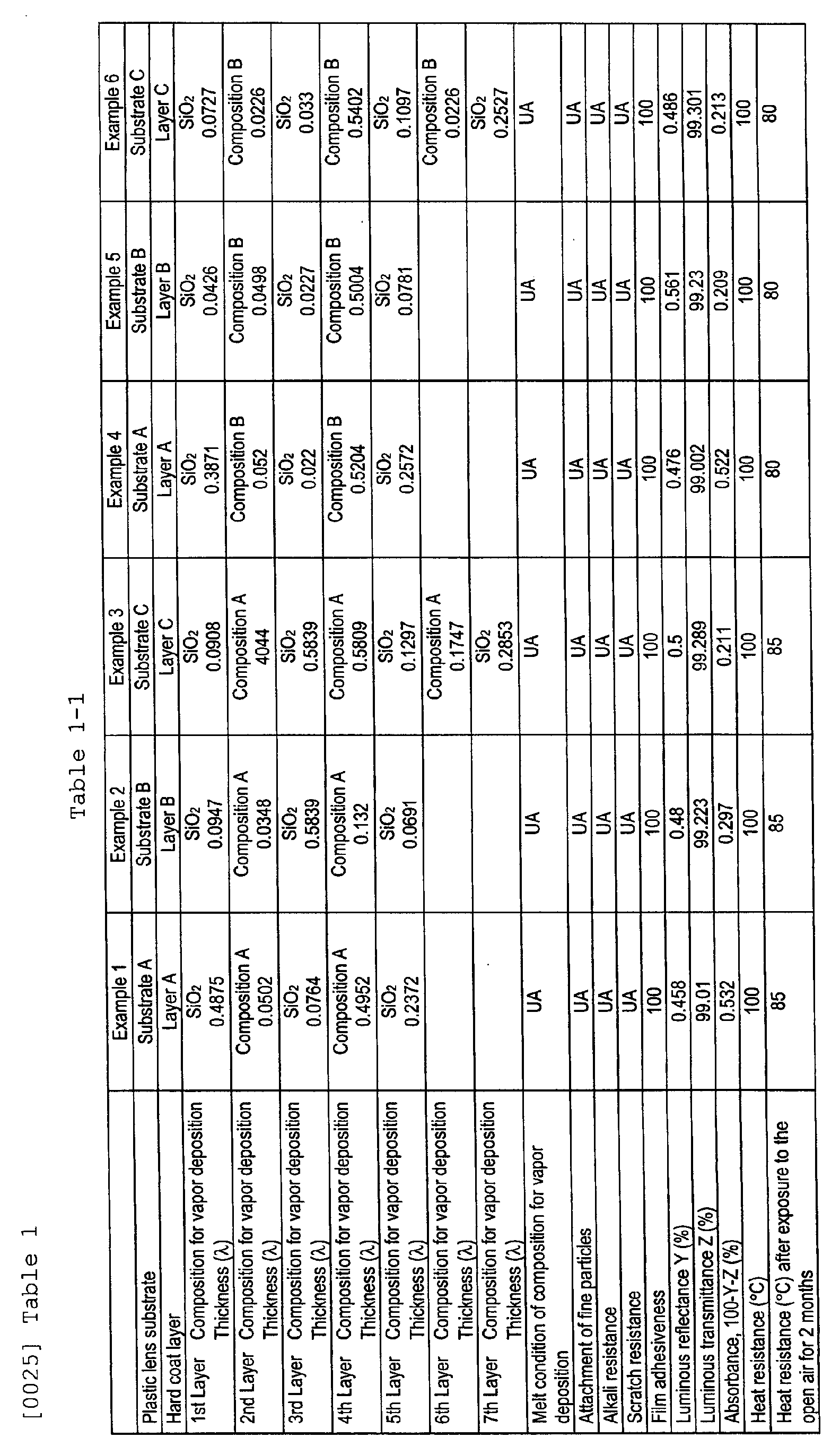
- Table 1 shows the plastic lens substrates, the hard coat layers, the composition for vapor deposition and the thickness of the constituent layers of the antireflection films, and the data of the physical properties in Examples and Comparative
- compositions A and B for vapor deposition of the invention used in Examples 1 to 6 were prevented from splashing, and stably deposited. Accordingly, attachment of fine particles by splashing was not found on the lens surface, and an excellent thin optical film was obtained.
- the antireflection film-coated plastic lenses of Examples 1 to 6 in which was used any of the composition A or B for vapor deposition of the invention all had better heat resistance as compared with the antireflection film-coated plastic lenses obtained in Comparative Examples 1 to 6, and their heat resistance lowered little with time.
- Composition A and Composition B in the Tables above mean that the layer was formed of the composition A or the composition B.
- compositions having compositional ratios between the compositions of the examples are also preferred.
- antireflection films having thicknesses between those disclosed in the examples are also preferred.
- optical elements, having layer structures between those disclosed in the examples are also preferred.
- the invention has made it possible to obtain an optical element having an antireflection film and having good heat resistance, which lowers little with time, even on a synthetic resin substrate that must be processed at low temperatures for vapor deposition thereon.
- composition of the invention and according to the method for forming an antireflection film of the invention, high-refraction layers can be formed within a shorter period of time, and the good physical properties intrinsic thereto are not worsened at all.
- the composition and the method of the invention ensure high working efficiency.
Landscapes
- Chemical & Material Sciences (AREA)
- Physics & Mathematics (AREA)
- Metallurgy (AREA)
- Chemical Kinetics & Catalysis (AREA)
- Engineering & Computer Science (AREA)
- Materials Engineering (AREA)
- Mechanical Engineering (AREA)
- Organic Chemistry (AREA)
- General Physics & Mathematics (AREA)
- Optics & Photonics (AREA)
- Inorganic Chemistry (AREA)
- Surface Treatment Of Optical Elements (AREA)
- Physical Vapour Deposition (AREA)
- Laminated Bodies (AREA)
- Compositions Of Oxide Ceramics (AREA)
Abstract
Description
It is desirable that the composition of the invention is formed by mixing a powder of niobium oxide (Nb2O5), a powder of zirconium oxide (ZrO2) and a powder of yttrium oxide (Y2O3), optionally, a powder of aluminum oxide (Al2O3), and optionally powders of other metal oxides (these powders mixed may sometimes be hereinafter referred to as powdery mixtures), and pressing the powdery mixture, followed by heating, for example, with electronic beams to thereby deposit its vapor on a substrate. The use of a sintered material in a pellet form prepared by pressing and sintering is more preferred because the vapor deposition time can be reduced. The amount of each oxide in the powdery mixture or in the sintered pellets may be properly varied, depending on the desired properties of the high-refraction layer to be formed.


Claims (15)
- A composition, which contains niobium oxide, zirconium oxide and yttrium oxide.
- The composition as claimed in claim 1, which comprises, based on the total amount of the composition, from 60 to 90 % by weight of niobium oxide (calculated in terms of Nb2O5).
- The composition according to claim 1 or 2, which comprises, based on the total amount of the composition, from 5 to 20 % by weight of zirconium oxide (calculated in terms of ZrO2).
- The composition according any one of claims 1 to 3, which comprises, based on the total amount of the composition, from 5 to 35 % by weight of yttrium oxide (calculated in terms of Y2O3).
- The composition as claimed in any one of claims 1 to 4, which additionally contains aluminum oxide.
- The composition as claimed in claim 5, wherein the aluminum oxide content (calculated in terms of Al2O3) is from 0.3 to 7.5 % by weight of the total of niobium oxide, zirconium oxide and yttrium oxide.
- Use of the composition according to any one of claims 1 to 6 for vapor deposition.
- A method for forming an antireflection film, which comprises sintering the composition
of any one of claims 1 to 6, vaporizing the resulting oxide, and depositing the vapor on a substrate. - The method according to claim 8, wherein the substrate is a plastic substrate optionally having formed one or more coating layers thereon.
- The method for forming an antireflection film as claimed in claim 8 or 9, which is combined with an ion-assisted process.
- An antireflection film comprising in an alternating fashion one or more layers of silicon dioxide and one or more layers obtainable according to the method of any one of claims 8 to 10.
- Use of the antireflection film according to claim 11 in an optical element.
- Use according to claim 12, wherein the optical element is selected from the group consisting of lenses for spectacles, lenses for cameras, windshields for automobiles, and optical filters to be fitted to displays of word processors.
- An optical element having a hard coat layer formed on a plastic substrate and having the antireflection film of claim 11 formed thereon.
- An optical element according to claim 14, which is selected from the group consisting of lenses for spectacles, lenses for cameras, windshields for automobiles, and optical filters to be fitted to displays of word processors.
Priority Applications (1)
| Application Number | Priority Date | Filing Date | Title |
|---|---|---|---|
| EP07007178A EP1801621B1 (en) | 2000-11-13 | 2001-11-13 | Optical coating material for vapor deposition, use of the material, and optical element |
Applications Claiming Priority (4)
| Application Number | Priority Date | Filing Date | Title |
|---|---|---|---|
| JP2000344928 | 2000-11-13 | ||
| JP2000344928 | 2000-11-13 | ||
| JP2001128157A JP3779174B2 (en) | 2000-11-13 | 2001-04-25 | Vapor deposition composition, method of forming antireflection film using the same, and optical member |
| JP2001128157 | 2001-04-25 |
Related Child Applications (1)
| Application Number | Title | Priority Date | Filing Date |
|---|---|---|---|
| EP07007178A Division EP1801621B1 (en) | 2000-11-13 | 2001-11-13 | Optical coating material for vapor deposition, use of the material, and optical element |
Publications (3)
| Publication Number | Publication Date |
|---|---|
| EP1205774A2 true EP1205774A2 (en) | 2002-05-15 |
| EP1205774A3 EP1205774A3 (en) | 2004-06-09 |
| EP1205774B1 EP1205774B1 (en) | 2007-05-30 |
Family
ID=26603823
Family Applications (2)
| Application Number | Title | Priority Date | Filing Date |
|---|---|---|---|
| EP07007178A Expired - Lifetime EP1801621B1 (en) | 2000-11-13 | 2001-11-13 | Optical coating material for vapor deposition, use of the material, and optical element |
| EP01126520A Expired - Lifetime EP1205774B1 (en) | 2000-11-13 | 2001-11-13 | Composition for vapor deposition, method for forming antireflection film using it, and optical element |
Family Applications Before (1)
| Application Number | Title | Priority Date | Filing Date |
|---|---|---|---|
| EP07007178A Expired - Lifetime EP1801621B1 (en) | 2000-11-13 | 2001-11-13 | Optical coating material for vapor deposition, use of the material, and optical element |
Country Status (11)
| Country | Link |
|---|---|
| US (1) | US7106515B2 (en) |
| EP (2) | EP1801621B1 (en) |
| JP (1) | JP3779174B2 (en) |
| KR (1) | KR100553010B1 (en) |
| CN (1) | CN1235065C (en) |
| AT (1) | ATE363667T1 (en) |
| AU (1) | AU752935B2 (en) |
| CA (1) | CA2360619C (en) |
| DE (1) | DE60128636T2 (en) |
| HU (1) | HU223735B1 (en) |
| TW (1) | TWI231864B (en) |
Cited By (2)
| Publication number | Priority date | Publication date | Assignee | Title |
|---|---|---|---|---|
| EP1211524A3 (en) * | 2000-11-30 | 2003-12-10 | Hoya Corporation | Method for producing composition for vapor deposition, composition for vapor deposition, and method for producing optical element with antireflection film |
| WO2009100750A1 (en) | 2008-02-14 | 2009-08-20 | Indo International S.A. | Polymeric based lens comprising a hardening layer, an interferential multi- layer and a hard layer sandwiched between both, and corresponding manufacturing method |
Families Citing this family (15)
| Publication number | Priority date | Publication date | Assignee | Title |
|---|---|---|---|---|
| JP3952198B2 (en) * | 2002-08-01 | 2007-08-01 | 日本ペイント株式会社 | Metal surface treatment method and galvanized steel sheet |
| CN100430754C (en) * | 2003-07-10 | 2008-11-05 | 柯尼卡美能达精密光学株式会社 | Optical component and optical pickup apparatus |
| JP2005302088A (en) * | 2004-04-07 | 2005-10-27 | Konica Minolta Opto Inc | Objective lens and optical pickup device |
| CN100361744C (en) * | 2005-08-23 | 2008-01-16 | 福州大学 | Hydrogen-rich water gas shift reaction catalyst and preparation method of the catalyst |
| MX2012010842A (en) * | 2010-03-22 | 2013-04-03 | Luxxotica Us Holdings Corp | Ion beam assisted deposition of ophthalmic lens coatings. |
| WO2011139856A2 (en) | 2010-04-29 | 2011-11-10 | Battelle Memorial Institute | High refractive index composition |
| JP2015505900A (en) * | 2011-11-29 | 2015-02-26 | コーニング インコーポレイテッド | Yttrium oxide coated optical element with improved mid-infrared performance |
| ES2536827B1 (en) * | 2013-11-27 | 2015-12-18 | Indo Optical S.L. | Ophthalmic lens comprising a base of polymeric material with a coating with a multilayer anti-reflective, anti-reflective and IR filter multilayer structure |
| CN205424492U (en) * | 2014-12-05 | 2016-08-03 | 嘉兴山蒲照明电器有限公司 | LED (Light -emitting diode) straight lamp |
| JP6443222B2 (en) * | 2015-05-26 | 2018-12-26 | 日亜化学工業株式会社 | Vapor deposition material and molded body thereof |
| KR101916778B1 (en) | 2017-07-28 | 2018-11-08 | 현대오트론 주식회사 | Camera apparatus for vehicle |
| CN110029310A (en) * | 2018-01-12 | 2019-07-19 | 北京优美科巨玻薄膜产品有限公司 | A kind of structural evaporation coating film material NbO2 and preparation method thereof |
| JP7121070B2 (en) | 2020-05-21 | 2022-08-17 | デクセリアルズ株式会社 | anti-reflection film |
| JP2022069258A (en) * | 2020-10-23 | 2022-05-11 | 東海光学株式会社 | Plastic optics and plastic eyeglass lenses |
| JP7203147B2 (en) * | 2020-11-09 | 2023-01-12 | ホヤ レンズ タイランド リミテッド | Spectacle lens manufacturing method |
Family Cites Families (25)
| Publication number | Priority date | Publication date | Assignee | Title |
|---|---|---|---|---|
| FR2276601A1 (en) * | 1974-06-27 | 1976-01-23 | France Etat | TAPE FILTERS AND APPLICATION TO THE MANUFACTURING OF PROTECTIVE GLASSES |
| US4116717A (en) * | 1976-12-08 | 1978-09-26 | The United States Of America As Represented By The Secretary Of The Air Force | Ion implanted eutectic gallium arsenide solar cell |
| DE2658418A1 (en) * | 1976-12-23 | 1978-06-29 | Leybold Heraeus Gmbh & Co Kg | PROCESS FOR THE PRODUCTION OF ANTIREFLEX COATING ON ACRYLIC GLASSES, OPTICAL BODIES PRODUCED BY THE PROCESS AND USE OF THE OPTICAL BODY |
| US4246043A (en) * | 1979-12-03 | 1981-01-20 | Solarex Corporation | Yttrium oxide antireflective coating for solar cells |
| JPS56116003A (en) | 1980-02-19 | 1981-09-11 | Hoya Corp | Optical part of synthetic resin having reflection preventing film |
| JPS59148002A (en) | 1983-02-15 | 1984-08-24 | Agency Of Ind Science & Technol | Zirconium oxide composition for vapor deposition and sputtering and production of optical thin film using said composition |
| JPS59154401A (en) | 1983-02-23 | 1984-09-03 | Canon Inc | Optical thin film and its manufacturing method |
| JP2613436B2 (en) * | 1988-06-10 | 1997-05-28 | 旭光学工業株式会社 | Method of forming antireflection film for plastic lens |
| CA1302547C (en) * | 1988-12-02 | 1992-06-02 | Jerzy A. Dobrowolski | Optical interference electroluminescent device having low reflectance |
| JP2561955B2 (en) | 1989-04-28 | 1996-12-11 | ホーヤ株式会社 | Multi-layer antireflection film for plastic lenses |
| US5181141A (en) | 1989-03-31 | 1993-01-19 | Hoya Corporation | Anti-reflection optical element |
| ES2075084T3 (en) | 1989-03-31 | 1995-10-01 | Hoya Corp | ANTI-REFLECTION OPTICAL ELEMENT. |
| JP2776553B2 (en) | 1989-04-28 | 1998-07-16 | ホーヤ株式会社 | Anti-reflective coating |
| ATE160107T1 (en) * | 1990-08-30 | 1997-11-15 | Viratec Thin Films Inc | METHOD FOR DEPOSING OPTICAL COATINGS CONTAINING NIOBOXIDE USING REACTIVE DC SPUTTING |
| JPH05188202A (en) * | 1992-01-10 | 1993-07-30 | Canon Inc | Multilayer optical thin film |
| US5521759A (en) * | 1993-06-07 | 1996-05-28 | National Research Council Of Canada | Optical filters for suppressing unwanted reflections |
| US5846649A (en) * | 1994-03-03 | 1998-12-08 | Monsanto Company | Highly durable and abrasion-resistant dielectric coatings for lenses |
| US5579162A (en) * | 1994-10-31 | 1996-11-26 | Viratec Thin Films, Inc. | Antireflection coating for a temperature sensitive substrate |
| IT1268814B1 (en) * | 1994-12-13 | 1997-03-06 | Calp Spa | GLAZING MIXTURE FOR QUALITY GLASS |
| FR2759360B1 (en) * | 1997-02-10 | 1999-03-05 | Commissariat Energie Atomique | INORGANIC POLYMERIC MATERIAL BASED ON TANTALOXIDE, IN PARTICULAR WITH A HIGH REFRACTION INDEX, MECHANICALLY RESISTANT TO ABRASION, ITS MANUFACTURING METHOD AND OPTICAL MATERIAL COMPRISING THE SAME |
| EP1051645A1 (en) * | 1998-01-27 | 2000-11-15 | Minnesota Mining And Manufacturing Company | Adhesion-enhancing coatings for optically functional coating materials |
| US6436541B1 (en) * | 1998-04-07 | 2002-08-20 | Ppg Industries Ohio, Inc. | Conductive antireflective coatings and methods of producing same |
| US6251813B1 (en) * | 1998-04-28 | 2001-06-26 | Hoya Corporation | Optical glass and its use |
| JP2000167969A (en) * | 1998-12-07 | 2000-06-20 | Nitto Denko Corp | Transparent laminate and filter for plasma display panel using the same |
| JP3712561B2 (en) | 1999-03-30 | 2005-11-02 | Hoya株式会社 | Optical member having cured coating |
-
2001
- 2001-04-25 JP JP2001128157A patent/JP3779174B2/en not_active Expired - Fee Related
- 2001-10-23 AU AU81552/01A patent/AU752935B2/en not_active Ceased
- 2001-10-29 CA CA002360619A patent/CA2360619C/en not_active Expired - Fee Related
- 2001-11-02 KR KR1020010068074A patent/KR100553010B1/en not_active Expired - Fee Related
- 2001-11-06 TW TW090127502A patent/TWI231864B/en not_active IP Right Cessation
- 2001-11-08 HU HU0104789A patent/HU223735B1/en not_active IP Right Cessation
- 2001-11-13 CN CNB011436859A patent/CN1235065C/en not_active Expired - Fee Related
- 2001-11-13 AT AT01126520T patent/ATE363667T1/en not_active IP Right Cessation
- 2001-11-13 US US09/986,907 patent/US7106515B2/en not_active Expired - Fee Related
- 2001-11-13 DE DE60128636T patent/DE60128636T2/en not_active Expired - Lifetime
- 2001-11-13 EP EP07007178A patent/EP1801621B1/en not_active Expired - Lifetime
- 2001-11-13 EP EP01126520A patent/EP1205774B1/en not_active Expired - Lifetime
Cited By (2)
| Publication number | Priority date | Publication date | Assignee | Title |
|---|---|---|---|---|
| EP1211524A3 (en) * | 2000-11-30 | 2003-12-10 | Hoya Corporation | Method for producing composition for vapor deposition, composition for vapor deposition, and method for producing optical element with antireflection film |
| WO2009100750A1 (en) | 2008-02-14 | 2009-08-20 | Indo International S.A. | Polymeric based lens comprising a hardening layer, an interferential multi- layer and a hard layer sandwiched between both, and corresponding manufacturing method |
Also Published As
| Publication number | Publication date |
|---|---|
| TWI231864B (en) | 2005-05-01 |
| HUP0104789A2 (en) | 2002-06-29 |
| HU0104789D0 (en) | 2002-01-28 |
| EP1801621B1 (en) | 2012-11-07 |
| HU223735B1 (en) | 2004-12-28 |
| US7106515B2 (en) | 2006-09-12 |
| CN1354370A (en) | 2002-06-19 |
| DE60128636T2 (en) | 2008-01-31 |
| JP2002205353A (en) | 2002-07-23 |
| JP3779174B2 (en) | 2006-05-24 |
| AU752935B2 (en) | 2002-10-03 |
| KR100553010B1 (en) | 2006-02-16 |
| KR20020037264A (en) | 2002-05-18 |
| CN1235065C (en) | 2006-01-04 |
| EP1205774A3 (en) | 2004-06-09 |
| DE60128636D1 (en) | 2007-07-12 |
| ATE363667T1 (en) | 2007-06-15 |
| EP1801621A3 (en) | 2009-12-02 |
| EP1801621A2 (en) | 2007-06-27 |
| CA2360619C (en) | 2007-06-12 |
| AU8155201A (en) | 2002-05-16 |
| EP1205774B1 (en) | 2007-05-30 |
| US20020089751A1 (en) | 2002-07-11 |
| CA2360619A1 (en) | 2002-05-13 |
Similar Documents
| Publication | Publication Date | Title |
|---|---|---|
| US6627320B2 (en) | Method for producing composition for vapor deposition, composition for vapor deposition, and method for producing optical element with antireflection film | |
| US6606196B2 (en) | Optical element having antireflection film | |
| US7106515B2 (en) | Composition for vapor deposition, method for forming an antireflection film, and optical element | |
| JP3737075B2 (en) | Optical member and antireflection film | |
| JP2020050945A (en) | Method for producing optical thin film, thin film forming material, optical thin film, and optical member | |
| JP2004300580A (en) | Method for manufacturing vapor deposition composition, and method for manufacturing optical component having vapor deposition composition and reflection preventive film | |
| JP2002328201A (en) | Optical member having antireflection film | |
| JP3547738B2 (en) | Optical member having antireflection film | |
| JPH03229202A (en) | Antireflection film for plastic lens |
Legal Events
| Date | Code | Title | Description |
|---|---|---|---|
| PUAI | Public reference made under article 153(3) epc to a published international application that has entered the european phase |
Free format text: ORIGINAL CODE: 0009012 |
|
| AK | Designated contracting states |
Kind code of ref document: A2 Designated state(s): AT BE CH CY DE DK ES FI FR GB GR IE IT LI LU MC NL PT SE TR |
|
| AX | Request for extension of the european patent |
Free format text: AL;LT;LV;MK;RO;SI |
|
| PUAL | Search report despatched |
Free format text: ORIGINAL CODE: 0009013 |
|
| AK | Designated contracting states |
Kind code of ref document: A3 Designated state(s): AT BE CH CY DE DK ES FI FR GB GR IE IT LI LU MC NL PT SE TR |
|
| AX | Request for extension of the european patent |
Extension state: AL LT LV MK RO SI |
|
| 17P | Request for examination filed |
Effective date: 20040705 |
|
| AKX | Designation fees paid |
Designated state(s): AT BE CH CY DE DK ES FI FR GB GR IE IT LI LU MC NL PT SE TR |
|
| 17Q | First examination report despatched |
Effective date: 20050504 |
|
| GRAP | Despatch of communication of intention to grant a patent |
Free format text: ORIGINAL CODE: EPIDOSNIGR1 |
|
| GRAS | Grant fee paid |
Free format text: ORIGINAL CODE: EPIDOSNIGR3 |
|
| GRAA | (expected) grant |
Free format text: ORIGINAL CODE: 0009210 |
|
| RAP1 | Party data changed (applicant data changed or rights of an application transferred) |
Owner name: HOYA CORPORATION |
|
| AK | Designated contracting states |
Kind code of ref document: B1 Designated state(s): AT BE CH CY DE DK ES FI FR GB GR IE IT LI LU MC NL PT SE TR |
|
| PG25 | Lapsed in a contracting state [announced via postgrant information from national office to epo] |
Ref country code: CH Free format text: LAPSE BECAUSE OF FAILURE TO SUBMIT A TRANSLATION OF THE DESCRIPTION OR TO PAY THE FEE WITHIN THE PRESCRIBED TIME-LIMIT Effective date: 20070530 Ref country code: FI Free format text: LAPSE BECAUSE OF FAILURE TO SUBMIT A TRANSLATION OF THE DESCRIPTION OR TO PAY THE FEE WITHIN THE PRESCRIBED TIME-LIMIT Effective date: 20070530 Ref country code: LI Free format text: LAPSE BECAUSE OF FAILURE TO SUBMIT A TRANSLATION OF THE DESCRIPTION OR TO PAY THE FEE WITHIN THE PRESCRIBED TIME-LIMIT Effective date: 20070530 |
|
| REG | Reference to a national code |
Ref country code: GB Ref legal event code: FG4D |
|
| REG | Reference to a national code |
Ref country code: CH Ref legal event code: EP |
|
| REG | Reference to a national code |
Ref country code: IE Ref legal event code: FG4D |
|
| REF | Corresponds to: |
Ref document number: 60128636 Country of ref document: DE Date of ref document: 20070712 Kind code of ref document: P |
|
| PG25 | Lapsed in a contracting state [announced via postgrant information from national office to epo] |
Ref country code: SE Free format text: LAPSE BECAUSE OF FAILURE TO SUBMIT A TRANSLATION OF THE DESCRIPTION OR TO PAY THE FEE WITHIN THE PRESCRIBED TIME-LIMIT Effective date: 20070830 |
|
| PG25 | Lapsed in a contracting state [announced via postgrant information from national office to epo] |
Ref country code: ES Free format text: LAPSE BECAUSE OF FAILURE TO SUBMIT A TRANSLATION OF THE DESCRIPTION OR TO PAY THE FEE WITHIN THE PRESCRIBED TIME-LIMIT Effective date: 20070910 |
|
| ET | Fr: translation filed | ||
| PG25 | Lapsed in a contracting state [announced via postgrant information from national office to epo] |
Ref country code: AT Free format text: LAPSE BECAUSE OF FAILURE TO SUBMIT A TRANSLATION OF THE DESCRIPTION OR TO PAY THE FEE WITHIN THE PRESCRIBED TIME-LIMIT Effective date: 20070530 |
|
| NLV1 | Nl: lapsed or annulled due to failure to fulfill the requirements of art. 29p and 29m of the patents act | ||
| REG | Reference to a national code |
Ref country code: CH Ref legal event code: PL |
|
| PG25 | Lapsed in a contracting state [announced via postgrant information from national office to epo] |
Ref country code: BE Free format text: LAPSE BECAUSE OF FAILURE TO SUBMIT A TRANSLATION OF THE DESCRIPTION OR TO PAY THE FEE WITHIN THE PRESCRIBED TIME-LIMIT Effective date: 20070530 |
|
| PG25 | Lapsed in a contracting state [announced via postgrant information from national office to epo] |
Ref country code: NL Free format text: LAPSE BECAUSE OF FAILURE TO SUBMIT A TRANSLATION OF THE DESCRIPTION OR TO PAY THE FEE WITHIN THE PRESCRIBED TIME-LIMIT Effective date: 20070530 Ref country code: DK Free format text: LAPSE BECAUSE OF FAILURE TO SUBMIT A TRANSLATION OF THE DESCRIPTION OR TO PAY THE FEE WITHIN THE PRESCRIBED TIME-LIMIT Effective date: 20070530 Ref country code: PT Free format text: LAPSE BECAUSE OF FAILURE TO SUBMIT A TRANSLATION OF THE DESCRIPTION OR TO PAY THE FEE WITHIN THE PRESCRIBED TIME-LIMIT Effective date: 20071030 |
|
| PLBE | No opposition filed within time limit |
Free format text: ORIGINAL CODE: 0009261 |
|
| STAA | Information on the status of an ep patent application or granted ep patent |
Free format text: STATUS: NO OPPOSITION FILED WITHIN TIME LIMIT |
|
| PG25 | Lapsed in a contracting state [announced via postgrant information from national office to epo] |
Ref country code: GR Free format text: LAPSE BECAUSE OF FAILURE TO SUBMIT A TRANSLATION OF THE DESCRIPTION OR TO PAY THE FEE WITHIN THE PRESCRIBED TIME-LIMIT Effective date: 20070831 Ref country code: IT Free format text: LAPSE BECAUSE OF FAILURE TO SUBMIT A TRANSLATION OF THE DESCRIPTION OR TO PAY THE FEE WITHIN THE PRESCRIBED TIME-LIMIT Effective date: 20070530 |
|
| 26N | No opposition filed |
Effective date: 20080303 |
|
| PG25 | Lapsed in a contracting state [announced via postgrant information from national office to epo] |
Ref country code: MC Free format text: LAPSE BECAUSE OF NON-PAYMENT OF DUE FEES Effective date: 20071130 |
|
| PG25 | Lapsed in a contracting state [announced via postgrant information from national office to epo] |
Ref country code: IE Free format text: LAPSE BECAUSE OF NON-PAYMENT OF DUE FEES Effective date: 20071113 |
|
| PG25 | Lapsed in a contracting state [announced via postgrant information from national office to epo] |
Ref country code: CY Free format text: LAPSE BECAUSE OF FAILURE TO SUBMIT A TRANSLATION OF THE DESCRIPTION OR TO PAY THE FEE WITHIN THE PRESCRIBED TIME-LIMIT Effective date: 20070530 |
|
| PG25 | Lapsed in a contracting state [announced via postgrant information from national office to epo] |
Ref country code: LU Free format text: LAPSE BECAUSE OF NON-PAYMENT OF DUE FEES Effective date: 20071113 |
|
| PG25 | Lapsed in a contracting state [announced via postgrant information from national office to epo] |
Ref country code: TR Free format text: LAPSE BECAUSE OF FAILURE TO SUBMIT A TRANSLATION OF THE DESCRIPTION OR TO PAY THE FEE WITHIN THE PRESCRIBED TIME-LIMIT Effective date: 20070530 |
|
| REG | Reference to a national code |
Ref country code: FR Ref legal event code: PLFP Year of fee payment: 15 |
|
| REG | Reference to a national code |
Ref country code: FR Ref legal event code: PLFP Year of fee payment: 16 |
|
| PGFP | Annual fee paid to national office [announced via postgrant information from national office to epo] |
Ref country code: FR Payment date: 20161014 Year of fee payment: 16 Ref country code: GB Payment date: 20161109 Year of fee payment: 16 Ref country code: DE Payment date: 20161108 Year of fee payment: 16 |
|
| REG | Reference to a national code |
Ref country code: DE Ref legal event code: R119 Ref document number: 60128636 Country of ref document: DE |
|
| GBPC | Gb: european patent ceased through non-payment of renewal fee |
Effective date: 20171113 |
|
| REG | Reference to a national code |
Ref country code: FR Ref legal event code: ST Effective date: 20180731 |
|
| PG25 | Lapsed in a contracting state [announced via postgrant information from national office to epo] |
Ref country code: DE Free format text: LAPSE BECAUSE OF NON-PAYMENT OF DUE FEES Effective date: 20180602 Ref country code: FR Free format text: LAPSE BECAUSE OF NON-PAYMENT OF DUE FEES Effective date: 20171130 |
|
| PG25 | Lapsed in a contracting state [announced via postgrant information from national office to epo] |
Ref country code: GB Free format text: LAPSE BECAUSE OF NON-PAYMENT OF DUE FEES Effective date: 20171113 |