EP1205747A2 - Humidity sensor - Google Patents
Humidity sensor Download PDFInfo
- Publication number
- EP1205747A2 EP1205747A2 EP01124532A EP01124532A EP1205747A2 EP 1205747 A2 EP1205747 A2 EP 1205747A2 EP 01124532 A EP01124532 A EP 01124532A EP 01124532 A EP01124532 A EP 01124532A EP 1205747 A2 EP1205747 A2 EP 1205747A2
- Authority
- EP
- European Patent Office
- Prior art keywords
- humidity
- gases
- signal
- transducer
- temperature
- Prior art date
- Legal status (The legal status is an assumption and is not a legal conclusion. Google has not performed a legal analysis and makes no representation as to the accuracy of the status listed.)
- Granted
Links
Images

Classifications
-
- G—PHYSICS
- G01—MEASURING; TESTING
- G01N—INVESTIGATING OR ANALYSING MATERIALS BY DETERMINING THEIR CHEMICAL OR PHYSICAL PROPERTIES
- G01N27/00—Investigating or analysing materials by the use of electric, electrochemical, or magnetic means
- G01N27/02—Investigating or analysing materials by the use of electric, electrochemical, or magnetic means by investigating impedance
- G01N27/22—Investigating or analysing materials by the use of electric, electrochemical, or magnetic means by investigating impedance by investigating capacitance
- G01N27/223—Investigating or analysing materials by the use of electric, electrochemical, or magnetic means by investigating impedance by investigating capacitance for determining moisture content, e.g. humidity
-
- A—HUMAN NECESSITIES
- A61—MEDICAL OR VETERINARY SCIENCE; HYGIENE
- A61M—DEVICES FOR INTRODUCING MEDIA INTO, OR ONTO, THE BODY; DEVICES FOR TRANSDUCING BODY MEDIA OR FOR TAKING MEDIA FROM THE BODY; DEVICES FOR PRODUCING OR ENDING SLEEP OR STUPOR
- A61M16/00—Devices for influencing the respiratory system of patients by gas treatment, e.g. ventilators; Tracheal tubes
- A61M16/10—Preparation of respiratory gases or vapours
- A61M16/14—Preparation of respiratory gases or vapours by mixing different fluids, one of them being in a liquid phase
- A61M16/16—Devices to humidify the respiration air
- A61M16/161—Devices to humidify the respiration air with means for measuring the humidity
-
- A—HUMAN NECESSITIES
- A61—MEDICAL OR VETERINARY SCIENCE; HYGIENE
- A61M—DEVICES FOR INTRODUCING MEDIA INTO, OR ONTO, THE BODY; DEVICES FOR TRANSDUCING BODY MEDIA OR FOR TAKING MEDIA FROM THE BODY; DEVICES FOR PRODUCING OR ENDING SLEEP OR STUPOR
- A61M16/00—Devices for influencing the respiratory system of patients by gas treatment, e.g. ventilators; Tracheal tubes
- A61M16/0057—Pumps therefor
- A61M16/0066—Blowers or centrifugal pumps
-
- A—HUMAN NECESSITIES
- A61—MEDICAL OR VETERINARY SCIENCE; HYGIENE
- A61M—DEVICES FOR INTRODUCING MEDIA INTO, OR ONTO, THE BODY; DEVICES FOR TRANSDUCING BODY MEDIA OR FOR TAKING MEDIA FROM THE BODY; DEVICES FOR PRODUCING OR ENDING SLEEP OR STUPOR
- A61M16/00—Devices for influencing the respiratory system of patients by gas treatment, e.g. ventilators; Tracheal tubes
- A61M16/10—Preparation of respiratory gases or vapours
- A61M16/14—Preparation of respiratory gases or vapours by mixing different fluids, one of them being in a liquid phase
- A61M16/16—Devices to humidify the respiration air
-
- A—HUMAN NECESSITIES
- A61—MEDICAL OR VETERINARY SCIENCE; HYGIENE
- A61M—DEVICES FOR INTRODUCING MEDIA INTO, OR ONTO, THE BODY; DEVICES FOR TRANSDUCING BODY MEDIA OR FOR TAKING MEDIA FROM THE BODY; DEVICES FOR PRODUCING OR ENDING SLEEP OR STUPOR
- A61M16/00—Devices for influencing the respiratory system of patients by gas treatment, e.g. ventilators; Tracheal tubes
- A61M16/0003—Accessories therefor, e.g. sensors, vibrators, negative pressure
- A61M2016/003—Accessories therefor, e.g. sensors, vibrators, negative pressure with a flowmeter
- A61M2016/0033—Accessories therefor, e.g. sensors, vibrators, negative pressure with a flowmeter electrical
- A61M2016/0039—Accessories therefor, e.g. sensors, vibrators, negative pressure with a flowmeter electrical in the inspiratory circuit
-
- A—HUMAN NECESSITIES
- A61—MEDICAL OR VETERINARY SCIENCE; HYGIENE
- A61M—DEVICES FOR INTRODUCING MEDIA INTO, OR ONTO, THE BODY; DEVICES FOR TRANSDUCING BODY MEDIA OR FOR TAKING MEDIA FROM THE BODY; DEVICES FOR PRODUCING OR ENDING SLEEP OR STUPOR
- A61M2205/00—General characteristics of the apparatus
- A61M2205/33—Controlling, regulating or measuring
- A61M2205/3368—Temperature
-
- A—HUMAN NECESSITIES
- A61—MEDICAL OR VETERINARY SCIENCE; HYGIENE
- A61M—DEVICES FOR INTRODUCING MEDIA INTO, OR ONTO, THE BODY; DEVICES FOR TRANSDUCING BODY MEDIA OR FOR TAKING MEDIA FROM THE BODY; DEVICES FOR PRODUCING OR ENDING SLEEP OR STUPOR
- A61M2205/00—General characteristics of the apparatus
- A61M2205/36—General characteristics of the apparatus related to heating or cooling
- A61M2205/3653—General characteristics of the apparatus related to heating or cooling by Joule effect, i.e. electric resistance
-
- G—PHYSICS
- G01—MEASURING; TESTING
- G01N—INVESTIGATING OR ANALYSING MATERIALS BY DETERMINING THEIR CHEMICAL OR PHYSICAL PROPERTIES
- G01N27/00—Investigating or analysing materials by the use of electric, electrochemical, or magnetic means
- G01N27/02—Investigating or analysing materials by the use of electric, electrochemical, or magnetic means by investigating impedance
- G01N27/04—Investigating or analysing materials by the use of electric, electrochemical, or magnetic means by investigating impedance by investigating resistance
- G01N27/12—Investigating or analysing materials by the use of electric, electrochemical, or magnetic means by investigating impedance by investigating resistance of a solid body in dependence upon absorption of a fluid; of a solid body in dependence upon reaction with a fluid, for detecting components in the fluid
- G01N27/121—Investigating or analysing materials by the use of electric, electrochemical, or magnetic means by investigating impedance by investigating resistance of a solid body in dependence upon absorption of a fluid; of a solid body in dependence upon reaction with a fluid, for detecting components in the fluid for determining moisture content, e.g. humidity, of the fluid
Definitions
- the present invention relates to the use of heated humidity sensors particularly though not solely to the use of heated humidity sensors with respiratory humidifiers for assisted patient breathing.
- Heated humidity sensors are hereby described that allow the measurement of humidity in gases having a dewpoint above the temperature of the surrounding environment. Problems associated with such gas streams include lack of sensor accuracy at high relative humidity and the possibility of liquid condensate flowing onto the sensor. A further disadvantage of measurement in high dewpoint gases is the possibility of sensor failure or misreading.
- Such humidity sensors could be used, for example, as part of a humidity-controlled medical humidifier. This introduces design constraints such as small size, robustness and ability to be sterilised to prevent cross-contamination between patients.
- capacitive-type humidity sensor is described, as well as how a heater and temperature sensor can be incorporated into the humidity sensor to allow stable temperature control of the humidity sensor at temperatures above that of the surrounding gas. This enables the humidity sensor to avoid condensation in gases of high humidity.
- the heater can be manufactured around or underneath the humidity sensor. It also describes how the heater element can be simultaneously used to measure temperature, i.e. the heater element and temperature sensor are combined in one element. This makes sensor construction easier.
- United States Patent No. 5,777,206 also describes a heated capacitive-type humidity sensor.
- a single resistor is used in this patent both as a heater and a temperature sensor, for controlling the humidity sensor temperature above the gas temperature.
- US5,777,206 also describes calculating the absolute or relative humidity from knowledge of the temperature of the sensor. Further disclosure includes a method for determining the gas flow rate based on the amount of heat being supplied to the beated capacitive sensor to determine the gas flow rate past the sensor.
- US5,777,206 uses a resistor to provide sensor beating and temperature measurement
- US4,143,177 uses a P-N semiconductor diode junction to provide the same functions.
- the present invention consists in a humidity sensing apparatus for sensing the absolute humidity of gases comprising:
- the present invention consists in a humidity sensing apparatus for sensing the absolute humidity of a flow of gases comprising:
- the invention may broadly be said to consist in a humidity sensing apparatus for sensing the absolute humidity of gases comprising:
- the present invention to consists in a gases delivery apparatus for suppling a flow of gases to a patient comprising:
- the present invention to consists in a method of sensing the absolute humidity of gases comprising the steps:
- the present invention to consists in a method of sensing the absolute humidity of gases comprising the steps:
- the present invention to consists in a method of sensing the absolute humidity of gases comprising the steps:
- the present invention to consists in a method of sensing the absolute humidity of gases comprising the steps:
- the present invention relates to a humidity sensor which is designed:
- Polymer absorption sensors are well known in the prior art and consist of two parts: a water-vapour porous polymer matrix, and a set of electrical sensing electrodes.
- the amount of water vapour which is absorbed into the polymer matrix is determined by the relative humidity of the gas in close contact with the polymer matrix,
- the electrodes allow the measurement of electrical properties related to the amount of water vapour in the polymer matrix.
- capacitance of the electrodes is measured, as the permittivity of the matrix changes with water content.
- electrical resistance or impedance can be measured.
- the invention as shown consists of a relative humidity sensor 1, which is mounted in close thermal contact with a heater 2 and a separate temperature sensor 3 to form assembly 11.
- Measurement circuitry 4 is connected to the humidity sensor 1 and gives an output in relative humidity 5.
- An adjustable power supply 6 is connected to the heater 2.
- Measurement circuitry 7 is connected to temperature sensor 3 to give a temperature signal 8 at its output.
- Control system 9 takes the temperature signal 8 and generates a control signal 10 so that temperature signal 8 remains constant at the desired temperature. In this way all of the elements of assembly 11 are kept at a constant temperature.
- the relative humidity sensor 1 is preferably of the polymer absorption type.
- the sensing mechanism measures capacitance of the polymer matrix 13 using the electrodes 12, although it could alternatively use resistance or impedance measurements of the polymer matrix.
- Absolute humidity of a gas can be calculated if the relative humidity and temperature are both known. This calculation is based on well-known physical principles. Due to its mode of operation, the polymer sensor measures the relative humidity of the measured gas at the temperature of the polymer matrix 13. Therefore absolute humidity of the gas can be calculated from the relative humidity measured by sensor 1 and the temperature of sensor 1 as measured by temperature sensor 3.
- Such a sensor can be used for measuring absolute humidity of any gases.
- the sensor is to be used for measuring medical gases.
- the medical gases are also respiratory gases, such as are found in a patient breathing circuit.
- a breathing circuit can be used to connect a patient to either a source of flowing gases, or to a respiratory ventilator.
- the senor is heated above the temperature of the gas to be measured, although it may be heated to any desired temperature.
- the temperature sensor 3 and heater 2 are separate components that are both thermally linked by being part of assembly 11. US4,143,177 and US5,777,206 both describe systems where the temperature sensing and hearing functions are combined in a single component.
- humidity sensor 1 Since there will be times when the sensing assembly 11 will be in an environment containing liquid water while the heater is off, it is essential that humidity sensor 1 be a water resistant sensor. Such sensors have only recently become available. Such a sensor will recover quickly from contact with liquid water, and this will have no lasting effects on the humidity calibration.
- the sensor as described may be mounted in several different ways.
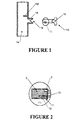
- a probe 110 could be inserted into a hole 18 in a tube 109 to measure the humidity of the gas inside 14, as shown in Figure 1.
- An alternative arrangement would be as a sensor permanently mounted inside a tube. With either arrangement it may be desirable to orient the sensing element in a particular direction in the tube. For instance, a horizontally facing sensing element 1 will cause liquid water on the sensor assembly 11 to run off the probe rather than onto the sensing element.
- a key 15 and keyway 16 can be used, as shown in Figure 1.
- FIG. 3 A respiratory system for delivering humidified gases to a patient 100 is shown, including a gases supply 102, a humidifier 104, a conduit 106 connecting the gases supply 102 to the humidifier 104, and a conduit 108 connecting the humidifier 104 to the patient 100.
- the conduit 108 conveying air flow from the humidifier 104 is substantially vertical in the section 109 immediately adjacent the humidifier 104.
- the humidity sensor 110 would be located in this vertical section 109.
- any liquids that were to condense in this vertical section 109 would likely flow down the sides of the conduit 108, some of which would then end up on the humidity sensor 110.
- a protruding lip 112 in the conduit 108 located above the humidity sensor 110 can be used to deflect liquid water to flow around the sensing assembly.
- the humidity sensor In a medical environment it is important to be able to sterilise the humidity sensor. Traditional methods such as autoclaving can be very harsh on a humidity sensor. Preferably the sensor assembly 11 would be able to survive autoclaving using steam at 136°C. Other common methods of sterilising a probe are to immerse the probe in a disinfectant. Preferably the sensor assembly 11 would survive this treatment.
- Another way of sterilising the heated humidity sensor would be to heat it above the pasteurisation temperature of common pathogens (bacteria and viruses).
- the hardiest bacteria, Legionella can be killed by temperatures of 60°C.
- the temperature of the sensor is high enough that it kills common pathogens.
- the temperature of the sensor is raised to a high temperature at turn-on to kill pathogens.
- the sensor is periodically heated to a high temperature to kill pathogens.
- the semi permeable membrane could be a cap which fits over the probe and attaches to the probe, or alternatively it could be attached to the hole in the tube which the humidity probe fits into.
- a further way to reduce the potential of cross-contamination would be to construct the sensor assembly out of bactericidal plastic.
- a humidity sensor When a humidity sensor is used as part of a humidity control system it is important to be able to detect whether the humidity sensor is functioning correctly or not. This is particularly important if the humidity sensor is used to control a medical humidifier, because excessive levels of absolute humidity can result in patient bums and inadequate levels can cause drying of bodily tissues.
- the sensor will read 100% relative humidity. If 100% relative humidity is measured, the amount of heating being supplied to heater 2 can be increased so that the temperature of assembly 11 increases. If the 100% relative humidity reading remains after the sensor has been heated to a sufficiently high temperature, then the sensor can be judged to be faulty (or covered in water).
- the power to heater 2 can be discontinued, and the temperature sensor 3 used to give an estimate of the dewpoint of the gas. This can be converted to an absolute humidity figure assuming 100% relative humidity. The true absolute humidity will only be equal or less than the estimated absolute humidity, so this method provides an upper limit on the humidity control to prevent patient burns.
- Flow can be measured directly using a flow rate sensor, e.g. by measuring heat loss from a heated body.
- the heated humidity sensor as described is such a heated body, and the amount of power required to keep the sensor assembly at a particular temperature will give an indication of the gas rate.
- a separate flow sensor could be used, or this information may be obtained electronically from the ventilator.
Landscapes
- Health & Medical Sciences (AREA)
- Chemical & Material Sciences (AREA)
- Life Sciences & Earth Sciences (AREA)
- General Health & Medical Sciences (AREA)
- Chemical Kinetics & Catalysis (AREA)
- Electrochemistry (AREA)
- Physics & Mathematics (AREA)
- Analytical Chemistry (AREA)
- Biochemistry (AREA)
- General Physics & Mathematics (AREA)
- Immunology (AREA)
- Pathology (AREA)
- Emergency Medicine (AREA)
- Animal Behavior & Ethology (AREA)
- Engineering & Computer Science (AREA)
- Anesthesiology (AREA)
- Biomedical Technology (AREA)
- Heart & Thoracic Surgery (AREA)
- Hematology (AREA)
- Pulmonology (AREA)
- Public Health (AREA)
- Veterinary Medicine (AREA)
- Investigating Or Analyzing Materials By The Use Of Electric Means (AREA)
- Investigating Or Analyzing Materials By The Use Of Fluid Adsorption Or Reactions (AREA)
- Investigating Or Analyzing Materials Using Thermal Means (AREA)
- Air Humidification (AREA)
- Apparatus For Disinfection Or Sterilisation (AREA)
Abstract
Description
Claims (21)
- A humidity sensing apparatus for sensing the absolute humidity of gases comprising:Characterised in that said apparatus further comprisinga humidity transducer providing a first signal, said first signal indicative of the relative humidity of said gases,heating means associated with or in substantial thermal contact with said humidity transducer and adapted to heat at least a portion of said humidity transducer depending on energisation power supplied thereto,temperature sensing means associated with or in substantial thermal contact with said humidity transducer and providing a second signal, said second signal indicative of the temperature of said humidity transducer, andcontrol means adapted to provide a first said energisation power to said heating means to heat said humidity transducer to an operating temperature and receives said first signal and said second signal and calculates an estimate of the absolute humidity of said gases based thereon,
wherein at least at some point during the operation of said apparatus said control means adapted to provide a second said energisation power to said heating means to heat said humidity transducer to a pasteurisation temperature, said pasteurisation temperature being adequate to substantially kill any common pathogens present on said humidity transducer. - A humidity sensing apparatus as claimed in claim 1 wherein said pasteurisation temperature is above 60°C.
- A humidity sensing apparatus as claimed in claims 1 or 2 wherein said operating temperature is above the temperature of said gases.
- A humidity sensing apparatus for sensing the absolute humidity of a flow of gases comprising:Characterised in that said apparatus further comprisinga humidity transducer providing a first signal, said first signal indicative of the relative humidity of said flow of gases,heating means associated with or in substantial thermal contact with said humidity transducer and adapted to heat at least a portion of said humidity transducer depending on energisation power supplied thereto,temperature sensing means associated with or in substantial thermal contact with said humidity transducer and providing a second signal, said second signal indicative of the temperature of said humidity transducer and,control means having storage means, and adapted to execute instructions stored in said storage means, said instructions comprising steps of:(i) providing a first said energisation power to said heating means to heat said humidity transducer to an operating temperature;(ii) receiving said first signal and said second signal;(iii) calculating an estimate of the absolute humidity of said flow of gases based on at least one of said first signal and/or said second signal;(iv) storing information on said absolute humidity over a period of time;(v) estimating the flow rate of said flow of gases based on at least one of said first signal, said second signal and/or said energisation power supplied to said heating means;(vi) storing information on said flow rate of said gases over said period of time in said storage means; and(vii) calculating a corrected absolute humidity value for said flow of gases during a portion of said period of time based on said information on said flow rate of gases during said portion in relation to said information on said flow rate of gases over said period of time and said information on said absolute humidity.
- A humidity sensing apparatus as claimed in claim 4 wherein said period of time at least relates to one breathing cycle of a patient receiving respiratory therapy using said flow of gases.
- A humidity sensing apparatus as claimed in claims 4 or 5 wherein said portion of said period of time relates to the inspiratory phase of said patient's breathing cycle.
- A humidity sensing apparatus as claimed in any one of claims 4 to 6 wherein said humidity sensing apparatus further comprises a flow rate sensor, providing a third signal, said third signal being indicative of the flow rate of said flow of gases and said step (v) instead comprising determining the flow rate of said flow of gases based on said third signal.
- A humidity sensing apparatus for sensing the absolute humidity of gases comprising:Characterised in that said apparatus further comprisinga humidity transducer providing a first signal, said first signal indicative of the relative humidity of said gases,heating means associated with or in substantial thermal contact with said humidity transducer and adapted to heat at least a portion of said humidity transducer depending on energisation power supplied thereto,temperature sensing means associated with or in substantial thermal contact with said humidity transducer and providing a second signal, said second signal indicative of the temperature of said humidity transducer, andcontrol means adapted to provide a first said energisation power to said heating means to heat said humidity transducer to an operating temperature and receives said first signal and said second signal and calculate an estimate of the absolute humidity of said gases based thereon,
wherein at least at some point during the operation of said apparatus said control mean adapted to determine whether the apparatus is operating correctly, based on at least one of said first signal, said second signal and/or said energisation power provided to said heating means. - A humidity sensing apparatus as claimed in claim 8 wherein said correct operation of said apparatus at least relates to whether said estimate of the absolute humidity of said gases is accurate within predetermined limits.
- A humidity sensing apparatus as claimed in claims 8 or 9 wherein said accuracy of said absolute humidity is monitored in at least one aspect by detecting the presence of liquid water on said humidity transducer,
- A humidity sensing apparatus as claimed in any of claims 8 to 10 wherein said detection of liquid water comprises the steps:a) storing absolute humidity values during normal operation;b) providing a third said energisation power to said heating means to heat said humidity transducer to the dewpoint of said gases (where the relative humidity just reaches 100%);c) comparing the absolute humidity reading at dew point with that during normal operating (stored in step (a)): and if there is a substantial difference providing a fourth signal indicative of incorrect or faulty operation.
- A humidity sensing apparatus as claimed in any one of claims 8 to 10 wherein said detection of liquid water comprises the steps of:a) determining whether said first signal indicates 100% relative humidity,h) providing a fourth said energisation power to said heating means to heat said humidity transducer to a substantially higher temperature;c) if the relative humidity does not reduce from 100% providing a fourth signal indicative of incorrect or faulty operation.
- A humidity sensing apparatus as claimed in claims 11 or 12 wherein if said fourth signal indicates incorrect or faulty operation said control means provides a fifth said energisation power to said heating means to heat said humidity transducer to substantially evaporate said liquid water therefrom.
- A humidity sensing apparatus as claimed in claims 11 or 12 wherein, if said fourth signal indicates incorrect or faulty operation said control means discontinuing said energisation power to said healing means, and using said second signal to estimate an upper limit for the absolute humidity of said flow of gases.
- A gases delivery apparatus for suppling a flow of gases to a patient comprising:Characterised in that said apparatus further comprisingcases supply means adapted to provide a flow of gases at a desired pressure,humidification means having and inlet and an outlet, said inlet adapted to be in fluid communication with said gases supply means said humidification means thereby providing water vapour to humidify said flow of gases as they pass through said humidification means,a conduit adapted to be connected to said outlet and accepting said flow of gases therefrom, said conduit including an interior and an exterior, said conduit conveying said flow of gases through said interior, and including a protrusion located in said interior, andhumidity sensing means adapted to be located in said interior providing an estimate of the absolute humidity of said flow of gases, in use said humidity sensing means fuxtapositioned below said protrusion, said protrusion thereby substantially preventing any liquid water from flowing down said conduit onto said humidity sensing means.
- A gases delivery apparatus as claimed in claim 15 wherein said gases conduit having an aperture including a keyway, said humidity sensing means comprising a humidity transducer provided in a sensor housing, said housing adapted to engage with said aperture and having a key which engages with said keyway in said aperture such that said housing can only be installed in said aperture in a single orientation.
- A gases delivery apparatus as claimed in claim 15 wherein said humidity sensing means is permanently housed within said conduit.
- A method of sensing the absolute humidity of gases comprising the steps:Characterised in that said apparatus further comprisingusing a humidity transducer to sense the relative humidity of said gases,heating at least a portion of said humidity transducer and sensing the temperature of said humidity transducer, andcalculating an estimate of the absolute humidity of said gases based on the power to heat said transducer, the temperature of said transducer and/or the relative humidity andheating said humidity transducer to a pasteurisation temperature, said pasteurisation temperature being adequate to substantially kill any common pathogens present on said humidity transducer.
- A method of sensing the absolute humidity of gases comprising the steps:Characterised in that said apparatus further comprisingusing a humidity sensor to sense the relative humidity of said gases,heating at least a portion of said humidity sensor to an operating temperature,calculating an estimate of the absolute humidity of said flow of gases based on at least one of said relative humidity and/or temperature of said sensor,storing information on said absolute humidity over a period of time,estimating the flow rate of said flow of gases based on at least one of said relative humidity, said temperature and/or the power required to heat said transducer,storing information on said flow rate of said gases over said period of time, andcalculating a corrected absolute humidity value for said flow of gases during a portion of said period of time based on said information on said flow rate of gases during said portion in relation to said information on said flow rate of gases over said period of time and said information on said absolute humidity.
- A method of sensing the absolute humidity of gases comprising the steps:Characterised in that said apparatus further comprisingusing a humidity sensor to sense the relative humidity of said gases,heating at least a portion of said humidity sensor to an operating temperature,calculating an estimate of the absolute humidity of said gases based on at least one of said relative humidity, said temperature and the power required to heat said sensor detecting whether the apparatus is operating correctly, based on at least one of said relative humidity, said temperature and/or the power required to heat said sensor.
- A method of sensing the absolute humidity of gases comprising the steps:Characterised in that said apparatus further comprisingproviding a flow of gases at a desired pressure,humidifying said flow of gases,conveying said flow of gases through the said interior of a conduit and providing a protrusion in said interior,positioning a humidity sensor below said protrusion, said protrusion thereby substantially preventing any liquid water from flowing down said interior onto said humidity sensor, andproviding an estimate of the absolute humidity of said flow of gases, based at least from the output of said humidity sensor.
Priority Applications (1)
| Application Number | Priority Date | Filing Date | Title |
|---|---|---|---|
| EP08103877A EP1965200A3 (en) | 2000-10-20 | 2001-10-12 | Humidity sensor |
Applications Claiming Priority (2)
| Application Number | Priority Date | Filing Date | Title |
|---|---|---|---|
| NZ50768200 | 2000-10-20 | ||
| NZ50768200 | 2000-10-20 |
Related Child Applications (1)
| Application Number | Title | Priority Date | Filing Date |
|---|---|---|---|
| EP08103877A Division EP1965200A3 (en) | 2000-10-20 | 2001-10-12 | Humidity sensor |
Publications (3)
| Publication Number | Publication Date |
|---|---|
| EP1205747A2 true EP1205747A2 (en) | 2002-05-15 |
| EP1205747A3 EP1205747A3 (en) | 2004-01-28 |
| EP1205747B1 EP1205747B1 (en) | 2009-04-08 |
Family
ID=19928194
Family Applications (2)
| Application Number | Title | Priority Date | Filing Date |
|---|---|---|---|
| EP01124532A Expired - Lifetime EP1205747B1 (en) | 2000-10-20 | 2001-10-12 | Humidity sensor |
| EP08103877A Withdrawn EP1965200A3 (en) | 2000-10-20 | 2001-10-12 | Humidity sensor |
Family Applications After (1)
| Application Number | Title | Priority Date | Filing Date |
|---|---|---|---|
| EP08103877A Withdrawn EP1965200A3 (en) | 2000-10-20 | 2001-10-12 | Humidity sensor |
Country Status (8)
| Country | Link |
|---|---|
| US (1) | US6895803B2 (en) |
| EP (2) | EP1205747B1 (en) |
| JP (2) | JP4131788B2 (en) |
| CN (2) | CN1249429C (en) |
| AT (1) | ATE428109T1 (en) |
| AU (1) | AU782173B2 (en) |
| CA (1) | CA2359520C (en) |
| DE (1) | DE60138259D1 (en) |
Cited By (5)
| Publication number | Priority date | Publication date | Assignee | Title |
|---|---|---|---|---|
| WO2005079670A1 (en) * | 2004-02-23 | 2005-09-01 | Sherwood Services Ag | Receptacle for sensors |
| JP2014528814A (en) * | 2011-10-14 | 2014-10-30 | フィッシャー アンド ペイケル ヘルスケア リミテッド | Medical tube and manufacturing method thereof |
| GB2567075A (en) * | 2012-04-05 | 2019-04-03 | Fisher & Paykel Healthcare Ltd | Respiratory assistance apparatus |
| US11433210B2 (en) | 2014-05-27 | 2022-09-06 | Fisher & Paykel Healthcare Limited | Gases mixing and measuring for a medical device |
| US11666720B2 (en) | 2015-12-02 | 2023-06-06 | Fisher & Paykel Healthcare Limited | Flow path sensing for flow therapy apparatus |
Families Citing this family (73)
| Publication number | Priority date | Publication date | Assignee | Title |
|---|---|---|---|---|
| DE10139881B4 (en) * | 2001-08-20 | 2017-06-08 | Resmed R&D Germany Gmbh | Apparatus for supplying a breathing gas and method for controlling the same |
| US6867602B2 (en) * | 2002-07-09 | 2005-03-15 | Honeywell International Inc. | Methods and systems for capacitive balancing of relative humidity sensors having integrated signal conditioning |
| CA2492637A1 (en) * | 2002-07-31 | 2004-02-05 | Fisher & Paykel Healthcare Limited | Isolated temperature sensor for humidification system |
| AU2003258918B2 (en) * | 2002-08-30 | 2005-11-17 | Fisher & Paykel Healthcare Limited | Humidification system |
| US7465425B1 (en) * | 2002-09-09 | 2008-12-16 | Yizhong Sun | Sensor and method for detecting analytes in fluids |
| AU2003278649B2 (en) * | 2002-11-01 | 2009-06-11 | Fisher & Paykel Healthcare Limited | System for sensing the delivery of gases to a patient |
| CN100398914C (en) * | 2003-04-25 | 2008-07-02 | 乐金电子(天津)电器有限公司 | Relative humidity sensor control circuit of microwave oven and cooking control method thereof |
| US20050247106A1 (en) * | 2004-05-06 | 2005-11-10 | Honeywell International, Inc. | Relative humidity sensor enclosed with ceramic heater |
| JP5058982B2 (en) * | 2005-05-26 | 2012-10-24 | フィッシャー アンド ペイケル ヘルスケア リミテッド | Respiratory device |
| US8739780B2 (en) | 2005-08-15 | 2014-06-03 | Resmed Limited | Low cost CPAP flow generator and humidifier assembly |
| CA2633151C (en) | 2005-12-15 | 2012-05-29 | Fisher & Paykel Healthcare Limited | Breathing assistance apparatus |
| DE102007011544B3 (en) * | 2007-03-09 | 2008-06-05 | Dräger Medical AG & Co. KG | Breathing moistener controlling method, involves adjusting output of dampness of gas, where measured electrical resistance or capacitance lies as measure of dew of gas, in preset desired value range with maximum and minimum values |
| US8118023B2 (en) * | 2008-01-09 | 2012-02-21 | Short Michael J | CPAP system and method of use |
| US9802022B2 (en) * | 2008-03-06 | 2017-10-31 | Resmed Limited | Humidification of respiratory gases |
| EP4706722A3 (en) | 2008-05-27 | 2026-05-06 | Fisher & Paykel Healthcare Limited | Control of humidifier chamber temperature for accurate humidity control |
| JP5230508B2 (en) * | 2009-03-31 | 2013-07-10 | アズビル株式会社 | Degradation diagnosis method for humidity sensor |
| JP5235756B2 (en) * | 2009-03-31 | 2013-07-10 | アズビル株式会社 | Degradation diagnosis method for humidity sensor |
| AU2010206053B2 (en) | 2009-07-31 | 2014-08-07 | ResMed Pty Ltd | Wire Heated Tube with Temperature Control System, Tube Type Detection, and Active Over Temperature Protection for Humidifier for Respiratory Apparatus |
| US8230716B2 (en) * | 2009-11-09 | 2012-07-31 | Delphi Technologies, Inc. | Method and system for diagnostics of a particulate matter sensor |
| JP5995289B2 (en) * | 2010-04-27 | 2016-09-21 | フィッシャー アンド ペイケル ヘルスケア リミテッド | Water out alarm |
| JP6382513B2 (en) | 2010-04-27 | 2018-08-29 | フィッシャー アンド ペイケル ヘルスケア リミテッド | Device for supplying gas to a patient |
| DE102010030338A1 (en) * | 2010-06-22 | 2011-12-22 | Robert Bosch Gmbh | Sensor module and operating method for this |
| JP5769462B2 (en) * | 2011-03-24 | 2015-08-26 | 株式会社エアレックス | Decontamination condition determination method |
| US8511651B2 (en) | 2011-03-29 | 2013-08-20 | Smiths Medical Asd, Inc. | Heater unit humidification chamber monitor |
| US20130201316A1 (en) | 2012-01-09 | 2013-08-08 | May Patents Ltd. | System and method for server based control |
| JP5884238B2 (en) * | 2012-03-05 | 2016-03-15 | ナガノサイエンス株式会社 | Humidity detection device and environmental test device equipped with the same |
| CA3176668A1 (en) * | 2012-03-15 | 2013-09-19 | Fisher & Paykel Healthcare Limited | Respiratory gas humidification system |
| US9974921B2 (en) | 2012-04-27 | 2018-05-22 | Fisher & Paykel Healthcare Limited | Usability features for respiratory humidification system |
| EP3912667B1 (en) | 2013-01-30 | 2025-03-19 | Fisher & Paykel Healthcare Limited | Respiratory assistance apparatus and disinfection method |
| NZ743034A (en) | 2013-02-01 | 2019-12-20 | ResMed Pty Ltd | Wire heated tube with temperature control system for humidifier for respiratory apparatus |
| US9746438B2 (en) * | 2013-02-06 | 2017-08-29 | Veris Industries, Llc | Humidity sensor with temperature compensation |
| WO2014142678A1 (en) | 2013-03-14 | 2014-09-18 | Fisher & Paykel Healthcare Limited | Catheter mount with suction port |
| US9329160B2 (en) * | 2013-04-05 | 2016-05-03 | Ford Global Technologies, Llc | Humidity sensor diagnostic method using condensation clearing heater |
| EP2816352B1 (en) * | 2013-06-21 | 2016-12-28 | Sensirion AG | Concentration measurements with a mobile device |
| GB2534496B (en) | 2013-09-13 | 2020-04-01 | Fisher & Paykel Healthcare Ltd | A cartridge for a respiratory humidifier |
| WO2015038014A1 (en) | 2013-09-13 | 2015-03-19 | Fisher And Paykel Healthcare Limited | Humidification system |
| EP3081929B1 (en) * | 2013-12-10 | 2019-04-10 | Hitachi Automotive Systems, Ltd. | Humidity measurement device |
| CN110947069A (en) | 2013-12-20 | 2020-04-03 | 费雪派克医疗保健有限公司 | Humidification system connection |
| WO2015119515A1 (en) | 2014-02-07 | 2015-08-13 | Fisher & Paykel Healthcare Limited | Respiratory humidification system |
| CN111481797B (en) | 2014-03-13 | 2023-03-21 | 瑞思迈私人有限公司 | Humidifier for respiratory therapy device |
| CN106164657B (en) * | 2014-04-04 | 2020-12-08 | 日立汽车系统株式会社 | Humidity detection device |
| CN116440376A (en) | 2014-04-16 | 2023-07-18 | 费雪派克医疗保健有限公司 | Method and system for delivering gas to a patient |
| WO2015159663A1 (en) * | 2014-04-16 | 2015-10-22 | 日立オートモティブシステムズ株式会社 | Humidity measurement device |
| US11173272B2 (en) | 2014-05-02 | 2021-11-16 | Fisher & Paykel Healthcare Limited | Gas humidification arrangement |
| AU2015259944B2 (en) | 2014-05-13 | 2020-07-02 | Fisher & Paykel Healthcare Limited | Usability features for respiratory humidification system |
| CN112370630A (en) | 2014-06-03 | 2021-02-19 | 费雪派克医疗保健有限公司 | Flow mixer for respiratory therapy system |
| US11278689B2 (en) | 2014-11-17 | 2022-03-22 | Fisher & Paykel Healthcare Limited | Humidification of respiratory gases |
| KR102538489B1 (en) | 2014-12-09 | 2023-05-30 | 플렉시케어, 인크. | Systems and methods for heating and humidifying inspired gases during mechanical ventilation |
| WO2016139645A1 (en) | 2015-03-05 | 2016-09-09 | Resmed Limited | A humidifier for a respiratory therapy device |
| CN104841054B (en) * | 2015-06-13 | 2017-01-18 | 高本梅 | Oxygen humidification device with functions of automatic alarming and timing |
| CN108027334B (en) * | 2015-09-30 | 2021-04-23 | 日立汽车系统株式会社 | Physical Quantity Detection Device |
| JP6421763B2 (en) * | 2016-01-13 | 2018-11-14 | トヨタ自動車株式会社 | Abnormality detection device for humidity sensor |
| PL3487571T3 (en) | 2016-07-21 | 2024-07-29 | Fisher & Paykel Healthcare Limited | Medical tubes for breathing circuit |
| US10364926B2 (en) | 2016-09-02 | 2019-07-30 | Veris Industries, Llc | Endcap for dry pressure insertion probe |
| WO2018106126A1 (en) | 2016-12-07 | 2018-06-14 | Fisher And Paykel Healthcare Limited | Sensing arrangements for medical devices |
| CN106691516B (en) * | 2017-03-06 | 2023-05-05 | 桂林市威诺敦医疗器械有限公司 | Skin tester with moisture detection function |
| WO2019043446A1 (en) | 2017-09-04 | 2019-03-07 | Nng Software Developing And Commercial Llc | A method and apparatus for collecting and using sensor data from a vehicle |
| JP7661041B2 (en) | 2018-01-24 | 2025-04-14 | フィッシャー アンド ペイケル ヘルスケア リミテッド | Medical tubing for breathing circuits |
| JP6960645B2 (en) * | 2018-06-21 | 2021-11-05 | フィガロ技研株式会社 | Gas detector and gas detection method |
| TWI665416B (en) * | 2018-08-07 | 2019-07-11 | 捷騰光電股份有限公司 | Sensing method of temperature and humidity sensing module |
| WO2020170237A1 (en) | 2019-02-19 | 2020-08-27 | Edgy Bees Ltd. | Estimating real-time delay of a video data stream |
| CN113631128A (en) * | 2019-03-25 | 2021-11-09 | 凯希特许有限公司 | Absorbent dressing with remote measurement of dressing moisture |
| EP4078162A1 (en) * | 2020-02-12 | 2022-10-26 | Gorenje, d.o.o. | Environmental control system suitable to operate at high temperatures for transient conditions with controled condensation effect |
| DE102020105479A1 (en) * | 2020-03-02 | 2021-09-02 | Hamm Ag | Work machine that can be moved on a ground |
| CN111529846A (en) * | 2020-03-10 | 2020-08-14 | 湖南明康中锦医疗科技发展有限公司 | Temperature and humidity sensor mounting structure and breathing machine |
| ES2974316T3 (en) * | 2020-03-16 | 2024-06-26 | Bayer Cropscience Kk | Information processor to diagnose the status of a humidity sensor |
| KR102438554B1 (en) * | 2020-03-26 | 2022-08-31 | (주)씨엠테크 | Sterilization apparatus and method of measuring hydrogen peroxide concentration of the sterilization apparatus |
| JP2023526599A (en) * | 2020-05-15 | 2023-06-22 | フィッシャー アンド ペイケル ヘルスケア リミテッド | Moisture detection in medical conduits carrying gases |
| CN113109378B (en) * | 2021-04-06 | 2022-09-27 | 山东省鲁南地质工程勘察院(山东省地勘局第二地质大队) | Steep rock surface water vapor condensation monitoring method |
| CN113587976B (en) * | 2021-06-09 | 2024-04-09 | 合肥通用机械研究院有限公司 | A wide temperature range air temperature and humidity sampling and measuring device |
| US20230044168A1 (en) * | 2021-08-04 | 2023-02-09 | Infosys Limited | Air purifier mask and method thereof |
| CN114432564B (en) * | 2022-01-28 | 2024-04-02 | 广州医软智能科技有限公司 | Method and device for monitoring humidity of ventilator pipeline |
| JP2024078904A (en) * | 2022-11-30 | 2024-06-11 | 株式会社村田製作所 | CPAP device |
Family Cites Families (18)
| Publication number | Priority date | Publication date | Assignee | Title |
|---|---|---|---|---|
| US3703696A (en) * | 1971-11-23 | 1972-11-21 | Gen Electric | Humidity sensor |
| US4143177A (en) | 1977-01-31 | 1979-03-06 | Panametrics, Inc. | Absolute humidity sensors and methods of manufacturing humidity sensors |
| JPS58105046A (en) * | 1981-12-18 | 1983-06-22 | Hitachi Ltd | Sensing element for temperature and humidity |
| JPS6076655A (en) * | 1983-10-03 | 1985-05-01 | Matsushita Electric Ind Co Ltd | Fault diagnosing type humidity detector |
| JPH0415554A (en) * | 1990-05-10 | 1992-01-20 | Ngk Spark Plug Co Ltd | Humidity measuring method |
| US5228436A (en) * | 1992-08-12 | 1993-07-20 | Marvin Bein | Proximal fluid trap |
| US5349946A (en) * | 1992-10-07 | 1994-09-27 | Mccomb R Carter | Microprocessor controlled flow regulated molecular humidifier |
| US5429123A (en) * | 1993-12-15 | 1995-07-04 | Temple University - Of The Commonwealth System Of Higher Education | Process control and apparatus for ventilation procedures with helium and oxygen mixtures |
| JP3358683B2 (en) * | 1994-10-03 | 2002-12-24 | リコーエレメックス株式会社 | Temperature and humidity measurement method and device |
| ATE239224T1 (en) | 1995-06-30 | 2003-05-15 | Klaus Zuechner | MEASURING DEVICE AND METHOD FOR DETERMINING THE WATER CONTENT IN A GAS |
| JPH09234247A (en) * | 1995-12-27 | 1997-09-09 | Nikkiso Y S I Kk | Ventilators and improved humidifiers |
| US5712421A (en) * | 1996-01-30 | 1998-01-27 | Arizona Instrument Corporation | Moisture analyzer |
| AT1469U1 (en) * | 1996-04-10 | 1997-05-26 | E & E Elektronik Gmbh | METHOD FOR DETERMINING ABSOLUTE HUMIDITY |
| JPH1057493A (en) * | 1996-08-19 | 1998-03-03 | Fuji R C Kk | Respirator humidity alarm |
| US5792938A (en) * | 1996-12-13 | 1998-08-11 | Panametrics, Inc. | Humidity sensor with differential thermal detection and method of sensing |
| CA2619893C (en) * | 1997-06-17 | 2011-11-15 | Fisher & Paykel Healthcare Limited | Respiratory humidification system |
| US6039696A (en) * | 1997-10-31 | 2000-03-21 | Medcare Medical Group, Inc. | Method and apparatus for sensing humidity in a patient with an artificial airway |
| AU3508799A (en) | 1998-06-19 | 2000-01-06 | Fisher & Paykel Healthcare Limited | Humidified sleep apnea treatment apparatus |
-
2001
- 2001-10-10 US US09/974,226 patent/US6895803B2/en not_active Expired - Lifetime
- 2001-10-12 EP EP01124532A patent/EP1205747B1/en not_active Expired - Lifetime
- 2001-10-12 AT AT01124532T patent/ATE428109T1/en not_active IP Right Cessation
- 2001-10-12 EP EP08103877A patent/EP1965200A3/en not_active Withdrawn
- 2001-10-12 DE DE60138259T patent/DE60138259D1/en not_active Expired - Lifetime
- 2001-10-17 AU AU79456/01A patent/AU782173B2/en not_active Ceased
- 2001-10-19 CA CA002359520A patent/CA2359520C/en not_active Expired - Lifetime
- 2001-10-19 CN CNB011364890A patent/CN1249429C/en not_active Expired - Fee Related
- 2001-10-19 JP JP2001321954A patent/JP4131788B2/en not_active Expired - Lifetime
- 2001-10-19 CN CNB2005100563820A patent/CN100573130C/en not_active Expired - Fee Related
-
2007
- 2007-09-11 JP JP2007235125A patent/JP4684270B2/en not_active Expired - Lifetime
Cited By (13)
| Publication number | Priority date | Publication date | Assignee | Title |
|---|---|---|---|---|
| WO2005079670A1 (en) * | 2004-02-23 | 2005-09-01 | Sherwood Services Ag | Receptacle for sensors |
| US7360398B2 (en) | 2004-02-23 | 2008-04-22 | Sherwood Services Ag | Receptacle for sensors |
| JP2014528814A (en) * | 2011-10-14 | 2014-10-30 | フィッシャー アンド ペイケル ヘルスケア リミテッド | Medical tube and manufacturing method thereof |
| US12263307B2 (en) | 2011-10-14 | 2025-04-01 | Fisher & Paykel Healthcare Limited | Medical tubes and methods of manufacture |
| US10980967B2 (en) | 2012-04-05 | 2021-04-20 | Fisher & Paykel Healthcare Limited | Respiratory assistance apparatus |
| GB2567075B (en) * | 2012-04-05 | 2019-08-21 | Fisher & Paykel Healthcare Ltd | Respiratory assistance apparatus |
| US10357629B2 (en) | 2012-04-05 | 2019-07-23 | Fisher & Paykel Healthcare Limited | Respiratory assistance apparatus |
| US11918748B2 (en) | 2012-04-05 | 2024-03-05 | Fisher & Paykel Healthcare Limited | Respiratory assistance apparatus |
| GB2567075A (en) * | 2012-04-05 | 2019-04-03 | Fisher & Paykel Healthcare Ltd | Respiratory assistance apparatus |
| US12296103B2 (en) | 2012-04-05 | 2025-05-13 | Fisher & Paykel Healthcare Limited | Respiratory assistance apparatus |
| US11433210B2 (en) | 2014-05-27 | 2022-09-06 | Fisher & Paykel Healthcare Limited | Gases mixing and measuring for a medical device |
| US12053585B2 (en) | 2014-05-27 | 2024-08-06 | Fisher & Paykel Healthcare Limited | Gases mixing and measuring for a medical device |
| US11666720B2 (en) | 2015-12-02 | 2023-06-06 | Fisher & Paykel Healthcare Limited | Flow path sensing for flow therapy apparatus |
Also Published As
| Publication number | Publication date |
|---|---|
| JP2007333750A (en) | 2007-12-27 |
| ATE428109T1 (en) | 2009-04-15 |
| JP4131788B2 (en) | 2008-08-13 |
| CN1667400A (en) | 2005-09-14 |
| EP1205747A3 (en) | 2004-01-28 |
| CA2359520A1 (en) | 2002-04-20 |
| EP1205747B1 (en) | 2009-04-08 |
| CA2359520C (en) | 2007-05-08 |
| CN1249429C (en) | 2006-04-05 |
| JP4684270B2 (en) | 2011-05-18 |
| AU7945601A (en) | 2002-05-02 |
| US20020078733A1 (en) | 2002-06-27 |
| EP1965200A3 (en) | 2008-10-29 |
| US6895803B2 (en) | 2005-05-24 |
| AU782173B2 (en) | 2005-07-07 |
| CN1350177A (en) | 2002-05-22 |
| EP1965200A2 (en) | 2008-09-03 |
| JP2002286677A (en) | 2002-10-03 |
| DE60138259D1 (en) | 2009-05-20 |
| CN100573130C (en) | 2009-12-23 |
Similar Documents
| Publication | Publication Date | Title |
|---|---|---|
| CA2359520C (en) | Humidity sensor | |
| US11458273B2 (en) | Apparatus for measuring properties of gases supplied to a patient | |
| JP7384850B2 (en) | Device that supplies gas to the patient | |
| US6102037A (en) | Respiration humidifier | |
| JP2002286677A5 (en) | ||
| US9440042B2 (en) | Humidified gases delivery apparatus and methods for controlling same | |
| JP3559551B2 (en) | Humidifier | |
| JP2019505297A5 (en) | ||
| US20080216829A1 (en) | Process for regulating a respiration humidifier as well as a corresponding device | |
| AU2005200071B2 (en) | Humidity sensor | |
| AU2017204480B2 (en) | Apparatus for Supplying Gases to a Patient |
Legal Events
| Date | Code | Title | Description |
|---|---|---|---|
| PUAI | Public reference made under article 153(3) epc to a published international application that has entered the european phase |
Free format text: ORIGINAL CODE: 0009012 |
|
| AK | Designated contracting states |
Kind code of ref document: A2 Designated state(s): AT BE CH CY DE DK ES FI FR GB GR IE IT LI LU MC NL PT SE TR |
|
| AX | Request for extension of the european patent |
Free format text: AL;LT;LV;MK;RO;SI |
|
| PUAL | Search report despatched |
Free format text: ORIGINAL CODE: 0009013 |
|
| AK | Designated contracting states |
Kind code of ref document: A3 Designated state(s): AT BE CH CY DE DK ES FI FR GB GR IE IT LI LU MC NL PT SE TR |
|
| AX | Request for extension of the european patent |
Extension state: AL LT LV MK RO SI |
|
| RIC1 | Information provided on ipc code assigned before grant |
Ipc: 7A 61M 16/00 B Ipc: 7G 01N 25/56 A |
|
| 17P | Request for examination filed |
Effective date: 20040423 |
|
| AKX | Designation fees paid |
Designated state(s): AT BE CH CY DE DK ES FI FR GB GR IE IT LI LU MC NL PT SE TR |
|
| 17Q | First examination report despatched |
Effective date: 20071126 |
|
| GRAP | Despatch of communication of intention to grant a patent |
Free format text: ORIGINAL CODE: EPIDOSNIGR1 |
|
| GRAS | Grant fee paid |
Free format text: ORIGINAL CODE: EPIDOSNIGR3 |
|
| GRAA | (expected) grant |
Free format text: ORIGINAL CODE: 0009210 |
|
| AK | Designated contracting states |
Kind code of ref document: B1 Designated state(s): AT BE CH CY DE DK ES FI FR GB GR IE IT LI LU MC NL PT SE TR |
|
| REG | Reference to a national code |
Ref country code: GB Ref legal event code: FG4D |
|
| REG | Reference to a national code |
Ref country code: CH Ref legal event code: EP |
|
| REG | Reference to a national code |
Ref country code: IE Ref legal event code: FG4D |
|
| REF | Corresponds to: |
Ref document number: 60138259 Country of ref document: DE Date of ref document: 20090520 Kind code of ref document: P |
|
| NLV1 | Nl: lapsed or annulled due to failure to fulfill the requirements of art. 29p and 29m of the patents act | ||
| PG25 | Lapsed in a contracting state [announced via postgrant information from national office to epo] |
Ref country code: PT Free format text: LAPSE BECAUSE OF FAILURE TO SUBMIT A TRANSLATION OF THE DESCRIPTION OR TO PAY THE FEE WITHIN THE PRESCRIBED TIME-LIMIT Effective date: 20090908 Ref country code: FI Free format text: LAPSE BECAUSE OF FAILURE TO SUBMIT A TRANSLATION OF THE DESCRIPTION OR TO PAY THE FEE WITHIN THE PRESCRIBED TIME-LIMIT Effective date: 20090408 Ref country code: ES Free format text: LAPSE BECAUSE OF FAILURE TO SUBMIT A TRANSLATION OF THE DESCRIPTION OR TO PAY THE FEE WITHIN THE PRESCRIBED TIME-LIMIT Effective date: 20090719 Ref country code: AT Free format text: LAPSE BECAUSE OF FAILURE TO SUBMIT A TRANSLATION OF THE DESCRIPTION OR TO PAY THE FEE WITHIN THE PRESCRIBED TIME-LIMIT Effective date: 20090408 |
|
| PG25 | Lapsed in a contracting state [announced via postgrant information from national office to epo] |
Ref country code: SE Free format text: LAPSE BECAUSE OF FAILURE TO SUBMIT A TRANSLATION OF THE DESCRIPTION OR TO PAY THE FEE WITHIN THE PRESCRIBED TIME-LIMIT Effective date: 20090708 Ref country code: NL Free format text: LAPSE BECAUSE OF FAILURE TO SUBMIT A TRANSLATION OF THE DESCRIPTION OR TO PAY THE FEE WITHIN THE PRESCRIBED TIME-LIMIT Effective date: 20090408 |
|
| PG25 | Lapsed in a contracting state [announced via postgrant information from national office to epo] |
Ref country code: DK Free format text: LAPSE BECAUSE OF FAILURE TO SUBMIT A TRANSLATION OF THE DESCRIPTION OR TO PAY THE FEE WITHIN THE PRESCRIBED TIME-LIMIT Effective date: 20090408 |
|
| PLBE | No opposition filed within time limit |
Free format text: ORIGINAL CODE: 0009261 |
|
| STAA | Information on the status of an ep patent application or granted ep patent |
Free format text: STATUS: NO OPPOSITION FILED WITHIN TIME LIMIT |
|
| PG25 | Lapsed in a contracting state [announced via postgrant information from national office to epo] |
Ref country code: BE Free format text: LAPSE BECAUSE OF FAILURE TO SUBMIT A TRANSLATION OF THE DESCRIPTION OR TO PAY THE FEE WITHIN THE PRESCRIBED TIME-LIMIT Effective date: 20090408 |
|
| 26N | No opposition filed |
Effective date: 20100111 |
|
| PG25 | Lapsed in a contracting state [announced via postgrant information from national office to epo] |
Ref country code: MC Free format text: LAPSE BECAUSE OF NON-PAYMENT OF DUE FEES Effective date: 20091031 |
|
| REG | Reference to a national code |
Ref country code: CH Ref legal event code: PL |
|
| PG25 | Lapsed in a contracting state [announced via postgrant information from national office to epo] |
Ref country code: LI Free format text: LAPSE BECAUSE OF NON-PAYMENT OF DUE FEES Effective date: 20091031 Ref country code: IE Free format text: LAPSE BECAUSE OF NON-PAYMENT OF DUE FEES Effective date: 20091012 Ref country code: CH Free format text: LAPSE BECAUSE OF NON-PAYMENT OF DUE FEES Effective date: 20091031 Ref country code: GR Free format text: LAPSE BECAUSE OF FAILURE TO SUBMIT A TRANSLATION OF THE DESCRIPTION OR TO PAY THE FEE WITHIN THE PRESCRIBED TIME-LIMIT Effective date: 20090709 |
|
| PG25 | Lapsed in a contracting state [announced via postgrant information from national office to epo] |
Ref country code: IT Free format text: LAPSE BECAUSE OF FAILURE TO SUBMIT A TRANSLATION OF THE DESCRIPTION OR TO PAY THE FEE WITHIN THE PRESCRIBED TIME-LIMIT Effective date: 20090408 |
|
| PG25 | Lapsed in a contracting state [announced via postgrant information from national office to epo] |
Ref country code: LU Free format text: LAPSE BECAUSE OF NON-PAYMENT OF DUE FEES Effective date: 20091012 |
|
| PG25 | Lapsed in a contracting state [announced via postgrant information from national office to epo] |
Ref country code: TR Free format text: LAPSE BECAUSE OF FAILURE TO SUBMIT A TRANSLATION OF THE DESCRIPTION OR TO PAY THE FEE WITHIN THE PRESCRIBED TIME-LIMIT Effective date: 20090408 |
|
| PG25 | Lapsed in a contracting state [announced via postgrant information from national office to epo] |
Ref country code: CY Free format text: LAPSE BECAUSE OF FAILURE TO SUBMIT A TRANSLATION OF THE DESCRIPTION OR TO PAY THE FEE WITHIN THE PRESCRIBED TIME-LIMIT Effective date: 20090408 |
|
| REG | Reference to a national code |
Ref country code: FR Ref legal event code: PLFP Year of fee payment: 15 |
|
| REG | Reference to a national code |
Ref country code: FR Ref legal event code: PLFP Year of fee payment: 16 |
|
| REG | Reference to a national code |
Ref country code: FR Ref legal event code: PLFP Year of fee payment: 17 |
|
| REG | Reference to a national code |
Ref country code: FR Ref legal event code: PLFP Year of fee payment: 18 |
|
| PGFP | Annual fee paid to national office [announced via postgrant information from national office to epo] |
Ref country code: FR Payment date: 20191024 Year of fee payment: 19 |
|
| PGFP | Annual fee paid to national office [announced via postgrant information from national office to epo] |
Ref country code: GB Payment date: 20191029 Year of fee payment: 19 Ref country code: DE Payment date: 20191227 Year of fee payment: 19 |
|
| REG | Reference to a national code |
Ref country code: DE Ref legal event code: R119 Ref document number: 60138259 Country of ref document: DE |
|
| GBPC | Gb: european patent ceased through non-payment of renewal fee |
Effective date: 20201012 |
|
| PG25 | Lapsed in a contracting state [announced via postgrant information from national office to epo] |
Ref country code: DE Free format text: LAPSE BECAUSE OF NON-PAYMENT OF DUE FEES Effective date: 20210501 Ref country code: FR Free format text: LAPSE BECAUSE OF NON-PAYMENT OF DUE FEES Effective date: 20201031 |
|
| PG25 | Lapsed in a contracting state [announced via postgrant information from national office to epo] |
Ref country code: GB Free format text: LAPSE BECAUSE OF NON-PAYMENT OF DUE FEES Effective date: 20201012 |