EP1205441A1 - Device for magnetically modifying fluid - Google Patents
Device for magnetically modifying fluid Download PDFInfo
- Publication number
- EP1205441A1 EP1205441A1 EP00927784A EP00927784A EP1205441A1 EP 1205441 A1 EP1205441 A1 EP 1205441A1 EP 00927784 A EP00927784 A EP 00927784A EP 00927784 A EP00927784 A EP 00927784A EP 1205441 A1 EP1205441 A1 EP 1205441A1
- Authority
- EP
- European Patent Office
- Prior art keywords
- ring
- magnets
- pipe
- core
- magnetic
- Prior art date
- Legal status (The legal status is an assumption and is not a legal conclusion. Google has not performed a legal analysis and makes no representation as to the accuracy of the status listed.)
- Granted
Links
Images


Classifications
-
- C—CHEMISTRY; METALLURGY
- C02—TREATMENT OF WATER, WASTE WATER, SEWAGE, OR SLUDGE
- C02F—TREATMENT OF WATER, WASTE WATER, SEWAGE, OR SLUDGE
- C02F1/00—Treatment of water, waste water, or sewage
- C02F1/48—Treatment of water, waste water, or sewage with magnetic or electric fields
- C02F1/481—Treatment of water, waste water, or sewage with magnetic or electric fields using permanent magnets
-
- F—MECHANICAL ENGINEERING; LIGHTING; HEATING; WEAPONS; BLASTING
- F02—COMBUSTION ENGINES; HOT-GAS OR COMBUSTION-PRODUCT ENGINE PLANTS
- F02M—SUPPLYING COMBUSTION ENGINES IN GENERAL WITH COMBUSTIBLE MIXTURES OR CONSTITUENTS THEREOF
- F02M27/00—Apparatus for treating combustion-air, fuel, or fuel-air mixture, by catalysts, electric means, magnetism, rays, sound waves, or the like
- F02M27/04—Apparatus for treating combustion-air, fuel, or fuel-air mixture, by catalysts, electric means, magnetism, rays, sound waves, or the like by electric means, ionisation, polarisation or magnetism
- F02M27/045—Apparatus for treating combustion-air, fuel, or fuel-air mixture, by catalysts, electric means, magnetism, rays, sound waves, or the like by electric means, ionisation, polarisation or magnetism by permanent magnets
Definitions
- This invention relates to an apparatus for magnetically modifying fluid and more particularly, to such an apparatus for magnetically modifying fluid passing through a pipe.
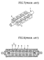
- FIG.7 of the accompanying drawings discloses an apparatus for magnetizing water wherein as shown in Fig.7 of the accompanying drawings, magnets 2 and 3 are disposed along the length of a pipe 1 on its opposite sides, the south and north poles of the magnets being oriented opposite to each other so that the magnetic lines of force are generated perpendicularly to a direction of flow of water through the pipe 11.
- Japanese Utility Model Publication Hei 6-1232 discloses an apparatus for modification of fluidic material comprising a barrel 1 of magnetic material, a block 4 including annular magnets 2 and annular pole pieces 3 of magnetic material arranged alternatively and disposed within the barrel 1, the same poles of the two adjacent magnets being oriented opposite to each other, and a fastening means for retaining the block 4 in it's assembled relation.
- the block 4 also includes a plurality of legs 5 of non-magnetic material and projecting from the periphery thereof for abutting the inner wall of the barrel 1 to define a passage 6 around the block 4 and between it and the barrel 1. Closed magnetic circuits are formed from the annular magnets through ones of the annular pole pieces 3, and the barrel 1 to the other adjacent annular pole pieces 3 to define magnetic paths across the fluid passage.
- the magnetic field id formed horizontally rather than over the entire interior of the pipe 11. For this reason, the activation of water is effected with a low efficiency.
- troublesome assembly is required because the block 4 includes many components and the plurality of legs 5 are acquired to support the block 4 within the barrel 1.
- the apparatus is of a weak construction incapable of resisting shock from the exterior.
- a main object of the invention is to provide an apparatus for magnetically modifying fluid, capable of forming high magnetic field over the entire interior of the pipe through which the fluid flows, and efficiently activating the fluid.
- Another object of the invention is to provide such an apparatus having simpler construction and which is easy to assembly and is strong enough to resist any shock from the exterior.
- an apparatus comprising a ring-like magnetic block including a ring-like core of magnetic material and a pair of ring-like magnets disposed on opposite sides of the core, and fitted over a pipe extending through a casing, fluid flowing through the pipe, each of the magnets having on its one side the north pole and on its other side the south pole, the south poles of the magnets in pair being oriented opposite to each other, and a P-type semiconductor on the inner peripheral surface of the ring-like core.
- a N-type semiconductor is provided on the inner peripheral surface of the casing in which the ring-like magnetic block is contained. This functions to absorb the N-pole magnetic field which is not required for modification of water.
- the ring-like core serve to prevent demagnetization of the magnets and may be of a different thickness to enlarge a range of electric field (Lorentz electric field). From these reasons.
- the casing containing the ring-like magnetic block is filled with weak magnetic oil such as vegetable oil, animal oil, CH oil or mixture of these oils.
- weak magnetic oil such as vegetable oil, animal oil, CH oil or mixture of these oils.
- FIG. 1 to 5 of the accompanying drawings there is shown therein an apparatus for magnetically modifying fluid, constructed in accordance with an embodiment of the invention.
- reference numeral 11 indicates a length of pipe through which fluid such as service water flows. External threads 12,12 are formed on the periphery of the pipe 11 at its opposite ends.
- a magnetic block 13 is mounted on the pipe 11 and comprises a pair of spaced apart ring-like magnets 14 and 14, and a ring-like core 15 of magnetic material interposed between the ring-like magnets 14 and 14.
- retainers 16 and 16 for retaining the ring-like magnets 14,14 and the ring-like core 15 on the pipe 11 in an abutment relation.
- the ring-like magnets 14 and 14 in pair have on their opposite faces the south poles and on their other faces the north poles.
- Each of the ring-like magnets 14, 14 and the ring- like core 15 includes a bore having an inner diameter substantially equal to an outer diameter of the pipe 11.
- the ring-like magnets 14,14 and the ring-like core 15 also have substantially the same outer diameter.
- Each of the retainers 16 and 16 has a larger outer diameter than that of each of the ring-like magnets 14,14 retainer and is provided with a circular recess 17 formed on the inward face thereof, in which each of the ring-like magnets 14,14 is fitted.
- Internal threads 18 are formed on the inner wall of a bore of each of the retainers 16,16 to engage the external threads 12 on the pipe 11.
- a casing 9 including a barrel 20 of magnetic material, and a pair of end caps 21, 21 positioned at the opposite ends of the barrel 20.
- the barrel 20 has an inner diameter slightly larger than the outer diameter of the retainers 16,16.
- Each of the end caps 21,21 has internal threads 22 formed on the inner wall of a bore therein to engage the external threads 12 on the pipe 11.
- the magnetic block 13 is provided by arranging the pair of ring-like magnets 14,14 such that their south poles are in a face to face relation, and interposing the ring-like core 15 between the ring-like magnets 14 and 14.
- the pipe 11 is then inserted into bores of the magnets 14 and the core 15 of the magnetic block 13.
- Each of the retainers 16, 16 is then threaded onto one of the opposite ends of the pipe 11 to retain on the later the ring- like magnets 14, 14 and the ring-like core 15 interposed therebetween. Inserted into the barrel 20 is the magnetic block 3 retained on the pipe 11 by the retainers 16, 16.
- the end caps 21,21 are threaded onto the threaded ends of the pipe 11 until they abut the end faces of the barrel 20 to sealingly containing the magnetic block 13 within the casing 19.
- the ring-like core 15 which may be of a predetermined thickness and interposed between the ring-like magnets 14 and 14, serves to reduce the self-demagnetizing force so that the magnetic lines of force act on the water.
- the magnetic lines of force also remove rust, scale or the like which would be deposited on the inner wall of the pipe 11.
- the ring- like core 15 having a different thickness may be employed to enlarge a range of the Lorentz electric field in addition to preventing the demagnetizing force of the ring-like magnets 14 and 14.
- a P-type semiconductor P is provided on the inner peripheral surface of the bore of the ring-like core 15 while a N-type semiconductor N is provided on the inner peripheral surface of the barrel 20 of the casing 19.
- the P-type semiconductor P causes a larger amount of the positive electric charge to be supplied into the magnetic field, thereby amplifying phenomenon of excitation of water. In addition, this results in generation of high uniform magnetic field through the pile 11 to make it possible to significantly improve the activation of the water molecular.
- N-type semiconductor N functions to absorb N-pole magnetic field which is not required for modification of the water, to obtain a high quality of water.
- the apparatus constructed in accordance with the present invention has, over a long distance, an ability to activate the water molecular, thereby modifying the water.
- the casing 19 may be filled with weak magnetic oil such as vegetable oil, animal oil, CH oil or mixture of these oils so that the magnetic field of the ring-like magnets 14 apparatus is not affected by magnetic action from the exterior. Thus, stabilization of the magnetic field 14 is achieved and in addition, any oxidation of the ring-like magnets 14 and the casing 19 can be prevented.
- Fig. 6 illustrates another embodiment of the apparatus according to the invention, which is substantially the same construction as the first embodiment with the exception that any retainers are not used.
- the apparatus for magnetically modifying fluid according to the invention is useful as apparatus for activating liquid such as service water and suitable for use in some circumstance being subject to magnetic effect from the exterior.
Landscapes
- Engineering & Computer Science (AREA)
- Chemical & Material Sciences (AREA)
- Life Sciences & Earth Sciences (AREA)
- Combustion & Propulsion (AREA)
- Mechanical Engineering (AREA)
- General Engineering & Computer Science (AREA)
- Chemical Kinetics & Catalysis (AREA)
- Hydrology & Water Resources (AREA)
- Environmental & Geological Engineering (AREA)
- Water Supply & Treatment (AREA)
- Organic Chemistry (AREA)
- Water Treatment By Electricity Or Magnetism (AREA)
- Physical Or Chemical Processes And Apparatus (AREA)
Abstract
Description
Claims (3)
- An apparatus comprising a ring-like magnetic block including a ring-like core of magnetic material and a pair of ring-like magnets disposed on opposite sides of the core, and fitted over a pipe extending through a casing, fluid flowing through said pipe, each of said magnets having on its one side the north pole and on its other side the south pole, the south poles of the magnets in pair being oriented opposite to each other, and a P-type semiconductor on the inner peripheral surface of said ring-like core.
- An apparatus according to claim 1, wherein a N-type semiconductor is provided on the inner peripheral surface of said casing.
- An apparatus according to claim 1 or 2, wherein the casing is filled with weak magnetic oil.
Applications Claiming Priority (3)
| Application Number | Priority Date | Filing Date | Title |
|---|---|---|---|
| JP13860299 | 1999-05-19 | ||
| JP13860299A JP3234915B2 (en) | 1999-05-19 | 1999-05-19 | Fluid magnetic reformer |
| PCT/JP2000/003150 WO2000071470A1 (en) | 1999-05-19 | 2000-05-17 | Device for magnetically modifying fluid |
Publications (3)
| Publication Number | Publication Date |
|---|---|
| EP1205441A1 true EP1205441A1 (en) | 2002-05-15 |
| EP1205441A4 EP1205441A4 (en) | 2003-01-02 |
| EP1205441B1 EP1205441B1 (en) | 2005-03-23 |
Family
ID=15225935
Family Applications (1)
| Application Number | Title | Priority Date | Filing Date |
|---|---|---|---|
| EP00927784A Expired - Lifetime EP1205441B1 (en) | 1999-05-19 | 2000-05-17 | Device for magnetically modifying fluid |
Country Status (6)
| Country | Link |
|---|---|
| US (1) | US6576126B1 (en) |
| EP (1) | EP1205441B1 (en) |
| JP (1) | JP3234915B2 (en) |
| AU (1) | AU762335B2 (en) |
| DE (1) | DE60018941T2 (en) |
| WO (1) | WO2000071470A1 (en) |
Cited By (2)
| Publication number | Priority date | Publication date | Assignee | Title |
|---|---|---|---|---|
| FR2856434A1 (en) * | 2003-06-17 | 2004-12-24 | Jen Chieh Wang | Liquid molecule e.g. fuel molecule, rearranging magnetic body for vehicle fuel tank cap, has magnetic powder layers mixed with viscous liquid and spread over outer surface of support for producing radiated magnetic field in tank |
| JP2023095249A (en) * | 2021-12-24 | 2023-07-06 | 三和レジン工業株式会社 | Vehicle improvement block and its mounting method |
Families Citing this family (8)
| Publication number | Priority date | Publication date | Assignee | Title |
|---|---|---|---|---|
| DE60023782T2 (en) | 1999-03-30 | 2006-07-20 | Mabuchi Motor Co., Ltd., Matsudo | Micromotor and its manufacturing process |
| JP2002203715A (en) * | 2000-12-28 | 2002-07-19 | Yoshino Corporation:Kk | Magnet body and fluid activation device using this magnet body |
| WO2003000596A1 (en) * | 2001-06-26 | 2003-01-03 | David Systems & Technology S.L. | Magnetic liquid treatment system |
| WO2005040047A1 (en) * | 2003-10-27 | 2005-05-06 | Y.T.Magnet Co., Ltd. | Process for producing reduced hydrogen water and apparatus therefor |
| KR100790340B1 (en) | 2007-03-13 | 2008-01-03 | 주식회사 파이랜드 | Magnetizer. |
| US20090092540A1 (en) * | 2007-10-05 | 2009-04-09 | Realm Industries | Method and apparatus of modifying bond angles of molecules |
| US7793621B2 (en) * | 2007-10-05 | 2010-09-14 | Realm Industries | Alternative fuel engine |
| US11322980B2 (en) * | 2018-10-31 | 2022-05-03 | Nissan North America, Inc. | Inductive power distribution in a vehicle |
Family Cites Families (13)
| Publication number | Priority date | Publication date | Assignee | Title |
|---|---|---|---|---|
| US4428837A (en) * | 1981-10-19 | 1984-01-31 | Trig International, Inc. | Fluid treatment device |
| US4605498A (en) * | 1984-04-06 | 1986-08-12 | Kulish Peter A | Apparatus for magnetic treatment of liquids |
| US4716024A (en) * | 1986-06-25 | 1987-12-29 | Goliarda Mugnai Trust | Magnetizing hydrocarbon fuels and other fluids |
| US4711271A (en) * | 1986-12-15 | 1987-12-08 | Weisenbarger Gale M | Magnetic fluid conditioner |
| US4933151A (en) * | 1988-12-16 | 1990-06-12 | Song Ben C | Device for magnetically treating hydrocarbon fuels |
| JPH0350236U (en) * | 1989-09-19 | 1991-05-16 | ||
| US5122277A (en) * | 1990-04-04 | 1992-06-16 | Jones Clifford I | Magnetic conditioner for fluid flow line |
| JP3050236B2 (en) | 1990-06-27 | 2000-06-12 | 株式会社島津製作所 | heatsink |
| JPH061232A (en) | 1992-06-19 | 1994-01-11 | Yamaha Motor Co Ltd | Rail cutoff mechanism of carrier |
| JPH0833840A (en) * | 1994-06-28 | 1996-02-06 | Aavan Ekorojii:Kk | Magnetizer and magnetization treatment and chemical reaction control method |
| JP2804458B2 (en) | 1995-05-16 | 1998-09-24 | 輝義 野田 | Water magnetizer |
| JPH09314150A (en) * | 1996-05-30 | 1997-12-09 | Tokin Corp | Magnetic processing device |
| JP3508089B2 (en) * | 1998-02-27 | 2004-03-22 | 博士 木口 | Electromagnetic wave generation complex |
-
1999
- 1999-05-19 JP JP13860299A patent/JP3234915B2/en not_active Expired - Fee Related
-
2000
- 2000-05-17 WO PCT/JP2000/003150 patent/WO2000071470A1/en not_active Ceased
- 2000-05-17 US US09/914,597 patent/US6576126B1/en not_active Expired - Fee Related
- 2000-05-17 EP EP00927784A patent/EP1205441B1/en not_active Expired - Lifetime
- 2000-05-17 AU AU56460/00A patent/AU762335B2/en not_active Ceased
- 2000-05-17 DE DE60018941T patent/DE60018941T2/en not_active Expired - Fee Related
Cited By (2)
| Publication number | Priority date | Publication date | Assignee | Title |
|---|---|---|---|---|
| FR2856434A1 (en) * | 2003-06-17 | 2004-12-24 | Jen Chieh Wang | Liquid molecule e.g. fuel molecule, rearranging magnetic body for vehicle fuel tank cap, has magnetic powder layers mixed with viscous liquid and spread over outer surface of support for producing radiated magnetic field in tank |
| JP2023095249A (en) * | 2021-12-24 | 2023-07-06 | 三和レジン工業株式会社 | Vehicle improvement block and its mounting method |
Also Published As
| Publication number | Publication date |
|---|---|
| EP1205441A4 (en) | 2003-01-02 |
| AU762335B2 (en) | 2003-06-26 |
| JP2000325962A (en) | 2000-11-28 |
| AU5646000A (en) | 2000-12-12 |
| EP1205441B1 (en) | 2005-03-23 |
| US6576126B1 (en) | 2003-06-10 |
| DE60018941D1 (en) | 2005-04-28 |
| DE60018941T2 (en) | 2005-07-28 |
| JP3234915B2 (en) | 2001-12-04 |
| WO2000071470A1 (en) | 2000-11-30 |
Similar Documents
| Publication | Publication Date | Title |
|---|---|---|
| US6576126B1 (en) | Device for magnetically modifying fluid | |
| US4372852A (en) | Magnetic device for treating hydrocarbon fuels | |
| US6768407B2 (en) | Magnetic field generator | |
| US7607430B2 (en) | Magnetically coupled humidifier container components | |
| US6427813B1 (en) | Magnetorheological fluid devices exhibiting settling stability | |
| US5024759A (en) | Magnetic treatment of fluids | |
| KR102338654B1 (en) | Bearing with magnetic fluid seal and reel for fishing including the same | |
| US5269916A (en) | Pipe protector/fluid ionizer employing magnetic condenser for producing concentrated force lines perpendicular to fluid flow | |
| US20070262028A1 (en) | Method and device for magnetically filtering fluids | |
| KR20050061507A (en) | Magnetic conditioning apparatus for diesel engine fuel | |
| CN1246865C (en) | Compound magnet of electromagnet and permanent magnet | |
| JP6830737B2 (en) | Magnetic force enhancer and water activation system | |
| WO1994018682A1 (en) | Permanent magnet | |
| JP3933516B2 (en) | Liquid magnetizer for use in flow path | |
| CA2312178A1 (en) | Magnetic apparatus for treating fluid fuels | |
| US6649053B2 (en) | Magnet assembly for an oil filter and an oil pan | |
| KR200374259Y1 (en) | Apparatus for generating water that form hexagon ring structure | |
| JP2004195341A (en) | Magnetic substance powder attracting device and magnet for the attracting device | |
| RU2091323C1 (en) | Apparatus for magnetically treating liquid | |
| JPH0615791U (en) | Magnetic device for water treatment | |
| RU98104229A (en) | MAGNET TUNNEL | |
| KR920001616Y1 (en) | Apparatus for scale preventives or preventing corrosion to use magnet in the inner parts of piping equipments | |
| RU32484U1 (en) | Apparatus for magnetic processing of matter | |
| JP2527907B2 (en) | Magnet attachment | |
| KR200321331Y1 (en) | Magnetizer |
Legal Events
| Date | Code | Title | Description |
|---|---|---|---|
| PUAI | Public reference made under article 153(3) epc to a published international application that has entered the european phase |
Free format text: ORIGINAL CODE: 0009012 |
|
| 17P | Request for examination filed |
Effective date: 20010523 |
|
| AK | Designated contracting states |
Kind code of ref document: A1 Designated state(s): DE FR GB IT |
|
| A4 | Supplementary search report drawn up and despatched |
Effective date: 20021115 |
|
| AK | Designated contracting states |
Kind code of ref document: A4 Designated state(s): DE FR GB IT |
|
| RIC1 | Information provided on ipc code assigned before grant |
Free format text: 7C 02F 1/48 A, 7B 03C 1/12 B, 7B 01J 19/08 B, 7B 01J 19/12 B, 7B 03C 1/30 B |
|
| 17Q | First examination report despatched |
Effective date: 20030207 |
|
| GRAP | Despatch of communication of intention to grant a patent |
Free format text: ORIGINAL CODE: EPIDOSNIGR1 |
|
| GRAS | Grant fee paid |
Free format text: ORIGINAL CODE: EPIDOSNIGR3 |
|
| GRAA | (expected) grant |
Free format text: ORIGINAL CODE: 0009210 |
|
| AK | Designated contracting states |
Kind code of ref document: B1 Designated state(s): DE FR GB IT |
|
| REG | Reference to a national code |
Ref country code: GB Ref legal event code: FG4D |
|
| REF | Corresponds to: |
Ref document number: 60018941 Country of ref document: DE Date of ref document: 20050428 Kind code of ref document: P |
|
| ET | Fr: translation filed | ||
| PLBE | No opposition filed within time limit |
Free format text: ORIGINAL CODE: 0009261 |
|
| STAA | Information on the status of an ep patent application or granted ep patent |
Free format text: STATUS: NO OPPOSITION FILED WITHIN TIME LIMIT |
|
| 26N | No opposition filed |
Effective date: 20051227 |
|
| PGFP | Annual fee paid to national office [announced via postgrant information from national office to epo] |
Ref country code: DE Payment date: 20070330 Year of fee payment: 8 |
|
| PGFP | Annual fee paid to national office [announced via postgrant information from national office to epo] |
Ref country code: GB Payment date: 20070502 Year of fee payment: 8 |
|
| PGFP | Annual fee paid to national office [announced via postgrant information from national office to epo] |
Ref country code: IT Payment date: 20070529 Year of fee payment: 8 |
|
| PGFP | Annual fee paid to national office [announced via postgrant information from national office to epo] |
Ref country code: FR Payment date: 20070330 Year of fee payment: 8 |
|
| GBPC | Gb: european patent ceased through non-payment of renewal fee |
Effective date: 20080517 |
|
| REG | Reference to a national code |
Ref country code: FR Ref legal event code: ST Effective date: 20090119 |
|
| PG25 | Lapsed in a contracting state [announced via postgrant information from national office to epo] |
Ref country code: FR Free format text: LAPSE BECAUSE OF NON-PAYMENT OF DUE FEES Effective date: 20080602 Ref country code: DE Free format text: LAPSE BECAUSE OF NON-PAYMENT OF DUE FEES Effective date: 20081202 |
|
| PG25 | Lapsed in a contracting state [announced via postgrant information from national office to epo] |
Ref country code: GB Free format text: LAPSE BECAUSE OF NON-PAYMENT OF DUE FEES Effective date: 20080517 |
|
| PG25 | Lapsed in a contracting state [announced via postgrant information from national office to epo] |
Ref country code: IT Free format text: LAPSE BECAUSE OF NON-PAYMENT OF DUE FEES Effective date: 20080517 |