EP1205052B1 - Verfahren zur einstellung einer datenübertragungsrate in einem feldbussystem - Google Patents
Verfahren zur einstellung einer datenübertragungsrate in einem feldbussystem Download PDFInfo
- Publication number
- EP1205052B1 EP1205052B1 EP00960393A EP00960393A EP1205052B1 EP 1205052 B1 EP1205052 B1 EP 1205052B1 EP 00960393 A EP00960393 A EP 00960393A EP 00960393 A EP00960393 A EP 00960393A EP 1205052 B1 EP1205052 B1 EP 1205052B1
- Authority
- EP
- European Patent Office
- Prior art keywords
- fieldbus
- transmission rate
- data transmission
- central unit
- bus
- Prior art date
- Legal status (The legal status is an assumption and is not a legal conclusion. Google has not performed a legal analysis and makes no representation as to the accuracy of the status listed.)
- Expired - Lifetime
Links
- 238000000034 method Methods 0.000 title claims abstract description 51
- 238000012546 transfer Methods 0.000 title description 85
- 230000001105 regulatory effect Effects 0.000 title 1
- 230000005540 biological transmission Effects 0.000 claims abstract description 37
- 230000008569 process Effects 0.000 claims abstract description 32
- 230000004044 response Effects 0.000 claims description 12
- 238000001514 detection method Methods 0.000 claims description 4
- 230000000977 initiatory effect Effects 0.000 claims 1
- 238000003860 storage Methods 0.000 description 19
- 238000004891 communication Methods 0.000 description 10
- 230000008901 benefit Effects 0.000 description 8
- 238000012545 processing Methods 0.000 description 7
- 230000007423 decrease Effects 0.000 description 5
- 238000011161 development Methods 0.000 description 5
- 230000006870 function Effects 0.000 description 4
- 230000035484 reaction time Effects 0.000 description 4
- 230000007246 mechanism Effects 0.000 description 3
- 230000008859 change Effects 0.000 description 2
- 238000010586 diagram Methods 0.000 description 2
- 238000005259 measurement Methods 0.000 description 2
- 238000012544 monitoring process Methods 0.000 description 2
- 238000003825 pressing Methods 0.000 description 2
- 230000001681 protective effect Effects 0.000 description 2
- 230000004888 barrier function Effects 0.000 description 1
- 238000001311 chemical methods and process Methods 0.000 description 1
- 238000012790 confirmation Methods 0.000 description 1
- 238000010276 construction Methods 0.000 description 1
- 238000012937 correction Methods 0.000 description 1
- 125000004122 cyclic group Chemical group 0.000 description 1
- 230000003247 decreasing effect Effects 0.000 description 1
- 230000004069 differentiation Effects 0.000 description 1
- 238000004519 manufacturing process Methods 0.000 description 1
- 230000001360 synchronised effect Effects 0.000 description 1
Images

Classifications
-
- H—ELECTRICITY
- H04—ELECTRIC COMMUNICATION TECHNIQUE
- H04L—TRANSMISSION OF DIGITAL INFORMATION, e.g. TELEGRAPHIC COMMUNICATION
- H04L12/00—Data switching networks
- H04L12/28—Data switching networks characterised by path configuration, e.g. LAN [Local Area Networks] or WAN [Wide Area Networks]
- H04L12/40—Bus networks
- H04L12/4013—Management of data rate on the bus
-
- H—ELECTRICITY
- H04—ELECTRIC COMMUNICATION TECHNIQUE
- H04L—TRANSMISSION OF DIGITAL INFORMATION, e.g. TELEGRAPHIC COMMUNICATION
- H04L12/00—Data switching networks
- H04L12/28—Data switching networks characterised by path configuration, e.g. LAN [Local Area Networks] or WAN [Wide Area Networks]
- H04L12/40—Bus networks
- H04L12/403—Bus networks with centralised control, e.g. polling
-
- G—PHYSICS
- G05—CONTROLLING; REGULATING
- G05B—CONTROL OR REGULATING SYSTEMS IN GENERAL; FUNCTIONAL ELEMENTS OF SUCH SYSTEMS; MONITORING OR TESTING ARRANGEMENTS FOR SUCH SYSTEMS OR ELEMENTS
- G05B2219/00—Program-control systems
- G05B2219/30—Nc systems
- G05B2219/31—From computer integrated manufacturing till monitoring
- G05B2219/31135—Fieldbus
-
- H—ELECTRICITY
- H04—ELECTRIC COMMUNICATION TECHNIQUE
- H04L—TRANSMISSION OF DIGITAL INFORMATION, e.g. TELEGRAPHIC COMMUNICATION
- H04L12/00—Data switching networks
- H04L12/28—Data switching networks characterised by path configuration, e.g. LAN [Local Area Networks] or WAN [Wide Area Networks]
- H04L12/40—Bus networks
- H04L2012/40208—Bus networks characterized by the use of a particular bus standard
- H04L2012/40215—Controller Area Network CAN
-
- H—ELECTRICITY
- H04—ELECTRIC COMMUNICATION TECHNIQUE
- H04L—TRANSMISSION OF DIGITAL INFORMATION, e.g. TELEGRAPHIC COMMUNICATION
- H04L12/00—Data switching networks
- H04L12/28—Data switching networks characterised by path configuration, e.g. LAN [Local Area Networks] or WAN [Wide Area Networks]
- H04L12/40—Bus networks
- H04L2012/4026—Bus for use in automation systems
-
- Y—GENERAL TAGGING OF NEW TECHNOLOGICAL DEVELOPMENTS; GENERAL TAGGING OF CROSS-SECTIONAL TECHNOLOGIES SPANNING OVER SEVERAL SECTIONS OF THE IPC; TECHNICAL SUBJECTS COVERED BY FORMER USPC CROSS-REFERENCE ART COLLECTIONS [XRACs] AND DIGESTS
- Y02—TECHNOLOGIES OR APPLICATIONS FOR MITIGATION OR ADAPTATION AGAINST CLIMATE CHANGE
- Y02D—CLIMATE CHANGE MITIGATION TECHNOLOGIES IN INFORMATION AND COMMUNICATION TECHNOLOGIES [ICT], I.E. INFORMATION AND COMMUNICATION TECHNOLOGIES AIMING AT THE REDUCTION OF THEIR OWN ENERGY USE
- Y02D30/00—Reducing energy consumption in communication networks
- Y02D30/50—Reducing energy consumption in communication networks in wire-line communication networks, e.g. low power modes or reduced link rate
Definitions
- the present invention relates to a method for adjustment a data transfer rate in a fieldbus system, the is suitable for controlling safety-critical processes and the at least one participant connected to a fieldbus includes.
- the invention further relates to a fieldbus system for Control of safety-critical processes with a fieldbus to which at least one participant is connected.
- Fieldbus systems of the aforementioned type have long been used in the different areas and used for different purposes.
- a safety device with a microprocessor discloses, in which a fieldbus for the transmission of data is proposed becomes.
- a fieldbus system is generally understood to be a system for data communication, ideally any Participants can be connected via the common Fieldbus communicate with each other. The communication of the Participants take place on the fieldbus using specified Protocols. Such a communication system is in conflict to an individual point-to-point communication connection between two participants, from their communication other participants completely excluded are. Examples of known fieldbus systems are the so-called CAN bus, the so-called Profibus or the so-called Interbus.
- field buses Although the use of field buses has numerous advantages all in view of the otherwise required, high cabling effort owns, their use was practical Previously used to control safety-critical processes not possible. The reason for this was that the fieldbuses given its freely accessible to any participant Structure required to control safety-critical processes Failure to guarantee failure. The However, the applicant has meanwhile developed a fieldbus system this also includes the requirements for safety-critical processes enough.
- safety-critical Process in the present case Process understood, of which an error occurs not negligible danger to humans or material Goods runs out. In a safety-critical process therefore guaranteed with 100% certainty in the ideal case be that the process in the presence of an error in a safe state is transferred.
- security critical Processes can also be sub-processes of larger, higher-level ones Overall processes.
- safety-critical processes are chemical processes where critical parameters must be kept in a specified area or even complex machine controls, such as hydraulic ones Press or an entire production line. at A hydraulic press can, for example, feed the material a safety-critical sub-process, the commissioning the pressing tool, on the other hand, is a safety-critical one Sub-process within the overall process. Further examples monitoring is for safety-critical (sub) processes of protective grids, protective doors or light barriers that Control of two-hand switches or the response to Emergency switch.
- a fieldbus system for Control of safety-critical processes is a defined and fast response time, which with the known systems for data transmission, for example via modem, does not matter.
- Such a fieldbus system must be able to operate within a predetermined defined response time, for example after the Pressing an emergency stop button to stop the process or interrupt to avoid possible damage.
- the attainable Response time essentially depends on the transmission rate of the fieldbus system. A high data transfer rate leads to a short reaction time because the load on the Fieldbus compared to lower data transfer rates decreases with the same number of participants. So that decreased the maximum time a participant can spend on the Release of the fieldbus for the own transmission of data have to wait.
- a communication architecture is known from EP 0 559 214 A1, which, for example, in motion control systems for Robot systems is used.
- the communication architecture sees a central control node (CCN) as well as distributed Control node (DCN).
- the central control node (CCN) controls the network function, including the setting belongs to the data transfer rate.
- the setting of the Data transfer rate takes place in that the CCN with a low default data transfer rate over a command the network sends to the DCNs with a higher data transfer rate to work. After submitting this The CCN must command the new data transfer rate of each node confirm in the network. In other words, that means the CCN sends a message to each node upon its confirmation then he waits.
- the object of the present invention is therefore to the method mentioned at the beginning for setting a data transmission rate and the fieldbus system mentioned above to further develop that a simple and flexible setting can be achieved is, in particular the response time of the fieldbus system remains within the required framework.
- the setting the data transfer rate must not have any influence on the safety of the fieldbus system.
- the object underlying the invention is in a method of the type mentioned in that the participant (s) in a first phase with a lower first Data transfer rate for a central one connected to the fieldbus Register the unit (central unit), the central unit in a second phase the data transfer rate the participant (s) to a predetermined higher second Value sets, the participant (s) in a third phase the higher data transfer rate again at the central unit log in and the central unit switches off the fieldbus if they have a variation in the number in the first and third Phase registered participants.
- control units clients
- signal units servers
- the advantage of the present invention is that by means of the central unit a setting of the data transfer rate possible that also meets safety-critical requirements. This is how the fieldbus system is switched on checked which nodes are connected to the fieldbus. For this, the central unit uses the lowest data transfer rate, for example 20 kbaud. The low data transfer rate ensures that regardless of the data link all participants can be reached. Subsequently the central unit sends a telegram to the connected Participants, with the command, set the data transfer rate to one increase the predetermined higher value (target value). This target value is selected so that all safety-critical parameters, such as bus load, response time etc. stay. The data transfer rate setting is now complete.
- the method according to the invention therefore leaves a very simple one and flexible setting of the data transfer rate without manual To have to intervene on the individual participants. Rather, the user can use the for the existing fieldbus system permissible data transmission rates (previously determined to be secure) on the central unit.
- Another advantage is that the security of the Fieldbus system is increased. If one should be in the first Phase of registered participants no new registration with the higher one Can make data transfer rate, for example because it is too far away from the transmitter, the fieldbus becomes immediate off. The process controlled via the fieldbus system will be placed in a safe state in response.
- the first Phase started when the fieldbus system was switched on.
- This measure has the advantage that the data transmission with the lower first data transfer rate occurs in one stage, in which the safety-critical process to be controlled still is not running, so that the short-term low data transfer rate and the associated longer response time is not critical.
- the central unit sends in the second phase to all participants data telegrams that the Command to switch the data transfer rate to the second Value included.
- the central unit preferably ends the third phase if since a participant's last registration a specified period of time without a new registration of a participant has passed.
- the data transmission rate is particularly preferred as the first value the standard transmission rate, for example 20 kbaud and the second value is the target value of the fieldbus system, for example 250 kbaud. These values have proven to be special in practice emphasized advantageous.
- This measure has the advantage that the fieldbus system does not must be completely switched off to connect a new participant to be able to. Should it not be possible for the participant The fieldbus system can be to register with the central unit be restarted to the process of setting the Let the data transfer rate run again, then a new second value can be used.
- the object underlying the invention is in one Fieldbus system of the type mentioned by the characterizing Features of claim 7 solved.
- Central unit provided with the Communicates with participants and includes a switching device, the data transfer rate on the fieldbus and among the participants from a first lower value to a second higher value Change value.
- the central unit has a first storage unit in which the first and second values of the data transfer rate is filed.
- the central unit includes furthermore a second and a third storage unit for storage of registration data, the registration data of the on Fieldbus connected participants are transmitted. Further the central unit includes a comparator device which credentials stored in the second and third storage units compares, the central unit if there is a mismatch performs a shutdown of the fieldbus.
- This fieldbus system enables only once in the system existing central unit a very simple Setting the data transfer rate of all on the fieldbus connected participants is taken over. If one or several participants are unable to deal with the from the Switching device predetermined higher data transfer rate The fieldbus system will register again with the central unit switched off immediately. The one controlled by the fieldbus system safety-critical process is thus in a safe state convicted so that it is not or faulty transmitting participants cannot be damaged.
- the central unit preferably comprises a time measuring device, which is connected to the comparator device and the comparison after a predetermined time has elapsed the data transfer rate initiated.
- the fieldbus is a serial one Bus, preferably a CAN bus.
- CAN buses are already being used on a large scale, so that corresponding control modules, for example Bus controller, as standard building blocks for building an inventive Fieldbus systems are available inexpensively.
- the participant has one Detection device that detects the data transmission rate and the subscriber's data transfer rate in response established.
- This measure has the advantage that a participant on the fieldbus can be connected without having to reset the fieldbus system start. Rather, the subscriber records the data transfer rate on the fieldbus and provides them for your own transmission accordingly. In other words, it is synchronized the newly connected participant on the running fieldbus without disturbing it. As soon as the participant receives the has found a suitable data transfer rate, he logs on the central unit.
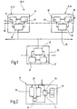
- Fig. 1 is a safe fieldbus system connected to it Bus participants marked with the reference number 10.
- the fieldbus system 10 is in the present exemplary embodiment a so-called CAN field bus system 11 (hereinafter briefly bus system called).
- the bus system 11 comprises a plurality of bus subscribers 12, 14, which via a so-called fieldbus 20 (hereinafter also called bus) are electrically connected to each other.
- a so-called fieldbus 20 hereinafter also called bus
- this bus consists of a two-wire line.
- the bus subscribers 12, 14 can be so-called control units (also called client) or so-called signal units act (also called server). As an example, let us assume that the bus subscriber 12 a control unit 13 and the Bus subscriber 14 forms a signal unit 15.
- Such a bus system 11 is suitable, for example, for certain To control processes.
- the control program necessary for control runs in the control unit 13, that of signal units Receives 15 data, for example measured values, this processes and corresponding control signals on signal units 15 sends.
- Signal units 15 can for example be connected to sensors and / or actuators. in principle the signal units therefore serve as input / output units (I / O units) while the control units 13 are processing of the measured values and in response the execution initiate defined actions.
- the communication of the bus participants 12, 14, i.e. the transfer the data via the bus 20 is based on certain rules, so-called protocols.
- data is transferred in accordance with the CAN protocol, that is known and therefore not described further for this reason shall be.
- controller module 16 which establishes the connection to the bus 20 and the user data to be transferred in protocol-compliant data frames packed and there on the bus 20 for transmission. It deals these controller modules 16 are standard elements, which are offered by different manufacturers. For this reason, their structure should not be discussed further become.
- the useful data to be transmitted for example measurement signals or Control commands are provided by units 17, 18.
- This Units 17, 18 can perform a wide variety of functions and be structured differently accordingly.
- the exemplary embodiment is that assigned to the control unit 13 Unit 17 is designed as a microcontroller, the corresponding performs defined algorithms while the unit 18 assigned to the signal unit 15, for example is an A / D converter, the measurement signals supplied by a sensor converted into digital signals.
- the two additional units 17 ', 18' should same functions as the corresponding units 17 and 18 to achieve a redundant system.
- the additional units are 17 ', 18' constructed identically to units 17 and 18, respectively (redundant system).
- the Build units 17, 17 'and 18, 18' as diverse systems, each having the same functionality additional units 17 'and 18' over the other units 17, 18 with other processors or processors of others Manufacturers are built.
- An example of an error check is, for example, the so-called “cyclic redundancy Check "(CRC).
- a line 19 is shown in dashed lines, the two bus participants 12, 14 in an upper safe part and separates a lower unsafe part.
- the non-secure Part includes the controller blocks 16 and the bus 20.
- Der safe part comprises the units 17, 17 ', 18, 18', which are themselves itself and the traffic on bus 20 with a very monitor the small probability of undetected errors.
- the data transmission via the bus 20 takes place with a specific one Speed, the so-called data transfer rate.
- a specific one Speed the so-called data transfer rate.
- a data transfer with the CAN bus system allows different data transfer rates 11 not too.
- the data transfer rate must be so high for safe bus systems be chosen so that the reaction time of the bus participants is one does not exceed the specified value.
- the response time mentioned is particularly affected by the availability of bus 20 certainly.
- the basic principle here is that the load on the Busses decreases with increasing data transfer rate. In order to the time that a bus subscriber 12, 14 has to wait also decreases, to transmit data over the bus 20.
- the maximum data transfer rate that can be set is limited due to the local expansion of the bus 20.
- This central processing unit 30 is connected to the bus 20 and comes only once in the bus system 11 in front. It takes over the setting of the data transfer rates for all bus users 12, 14 connected to bus 20. Of course, it is also conceivable that the bus participants 12, 14 are divided into groups and via the central unit 30 can be addressed in groups.
- the central processing unit 30 is also in a non-safe part and a safe part separately.
- the unsafe part also includes a controller chip 16, the management of data transmission over the bus 20 takes over.
- this controller module 16 there is a redundant one diverse system consisting of two units 31, 31 ' intended.
- the two units 31, 31 ' have the same Functionality that will be explained in more detail later.
- the unit 31 comprises a control unit 33 which is connected to a first Storage unit 35 is connected.
- the storage unit 35 comprises multiple memory cells to store multiple data.
- the control unit 33 is also equipped with two further storage units 36, 37 connected to the storage of so-called Registration data are designed.
- the two storage units 36, 37 are in turn connected to a comparator unit 38, which supplies an output signal to the control unit 33.
- the control unit 33 is still with one so-called timer block 39 provided.
- the central unit 30 and in particular the unit 31 now exercises the following function, referring to the flowchart for explanation 3 is referred to.
- the controller modules 16 lower predetermined data transfer rate, preferably 20 kBaud.
- This lower value (default value) is in one Memory cell of the memory unit 35 of the central unit and in corresponding memory cells (not shown) of the bus subscribers 12, 14 filed.
- the selected value should ensure that all bus subscribers 12, 14 connected to the bus 20 regardless of the extension of the bus 20 - communicate can.
- the electrical properties of the bus Lines are said to be at this low data transfer rate not have a negative impact.
- the bus subscribers 12, 14 transmit at the lower data transmission rate now in this first phase data telegrams over the bus 20, all of which are addressed to the central processing unit 30.
- These data telegrams contain data that a recognition or Allow identification of the sending bus subscriber 12, 14.
- These so-called login data are processed by the central unit 30 received and stored in the second storage unit 36.
- the control unit 33 reads from the first storage unit 35 there before switching on the bus system filed date.
- This date represents one Value of a data transfer rate that is based on security Aspects of the maximum permissible data transfer rate equivalent. This date or this value is stored in a data telegram packed and over the bus 20 to all bus participants 12, 14 sent.
- the bus participants 12, 14 receive this data telegram (For example, a so-called broadcast telegram that is sent to everyone Is addressed) and process the contained User data such that they the set data transfer rate switch to the new value.
- the aforementioned data telegram is still from the central processing unit 30 at the lower data transfer rate Posted.
- the bus participants 12, 14 After receiving the data telegram and converting the data transfer rate to the larger value, preferably 200-250 kBaud, the bus participants 12, 14 report again to the central unit 30 on. For this they send with the higher data transfer rate data telegrams addressed to the central processing unit 30, that contain the login information. These credentials are stored in the third storage unit 37.
- the control unit 33 issues the command the comparator unit 38 that in the two storage units 36, 37 compare stored login data. It turns out that after increasing the data transfer rate certain bus participants have not logged on again have, the control unit 33 concludes an error and switches the bus system off immediately, so that the controlled safety-critical processes in a safe state be transferred.
- a possible error could be, for example, that a bus device for the set higher data transfer rate is too far away from the central unit 30. Around To fix this error, it is necessary to use the bus system drive a lower data transfer rate. Such a the lower value is in another of the memory cells Storage unit 35 filed.
- the bus system 11 can with the set Data transfer rate work. All participants are in the Able to communicate at this data transfer rate.
- the CPU 30 cyclically checked whether all initially registered Participants still exist, i.e. ready to send and receive are. This check is carried out by the central unit 30 sends a data telegram via the bus 20, that contains the command for the bus subscribers 12, 14, login data returned. These credentials are in turn in the third storage unit 37 stored and after a through the timer block 39 predetermined period of time with the initially detected Login data compared. A mismatch of the Registration data leads to immediate shutdown of the bus system 11, during a match of the data no further actions entails.
- bus participants 12, 14 during the operation of the Bus system 11 connected with the high data transfer rate units 17, 17 ', 18 and 18' should have one Data transfer rate detection unit 40.
- These recognition units 40 serve the existing on the bus 20 Detect data transfer rate and the controller block 16 set accordingly.
- the new one sends Bus participants 12, 14 send a data telegram to the central unit 30 to log in there.
- the corresponding login data are stored in the second memory unit 36 in this case.
- the registration data of the newly connected bus participant in the third Storage unit 37 filed, so that the comparison to a Match.
- the first storage unit 35 comprises one Variety of memory cells that have different values for Can record data transfer rates. These data transfer rates can be set up before starting the central unit 30 enter. Of course, it is also conceivable to use this data change during operation. Typical values for saved Data transfer rates are 20 kbaud as the standard starting value, 50 kBaud, 100 kBaud, 125 kBaud, 150 kBaud, 200 kBaud, 250 kBaud and 500 KBaud. Of course, too other gradations conceivable.
- central unit 30 can be combined with the functionality of other bus users can without departing from the scope of the invention. It is conceivable to integrate the central unit 30 into a control unit 13. In addition, it is entirely possible to use unit 31 in a different way than shown in FIG. 2 in order to to achieve the same functionality.
Landscapes
- Engineering & Computer Science (AREA)
- Computer Networks & Wireless Communication (AREA)
- Signal Processing (AREA)
- Quality & Reliability (AREA)
- Small-Scale Networks (AREA)
- Safety Devices In Control Systems (AREA)
Applications Claiming Priority (3)
| Application Number | Priority Date | Filing Date | Title |
|---|---|---|---|
| DE19939568 | 1999-08-20 | ||
| DE19939568A DE19939568C1 (de) | 1999-08-20 | 1999-08-20 | Verfahren zur Einstellung einer Datenübertragungsrate in einem Feldbussystem |
| PCT/EP2000/007583 WO2001015391A1 (de) | 1999-08-20 | 2000-08-04 | Verfahren zur einstellung einer datenübertragungsrate in einem feldbussystem |
Publications (2)
| Publication Number | Publication Date |
|---|---|
| EP1205052A1 EP1205052A1 (de) | 2002-05-15 |
| EP1205052B1 true EP1205052B1 (de) | 2004-07-28 |
Family
ID=7919069
Family Applications (1)
| Application Number | Title | Priority Date | Filing Date |
|---|---|---|---|
| EP00960393A Expired - Lifetime EP1205052B1 (de) | 1999-08-20 | 2000-08-04 | Verfahren zur einstellung einer datenübertragungsrate in einem feldbussystem |
Country Status (7)
| Country | Link |
|---|---|
| US (1) | US7020711B2 (enExample) |
| EP (1) | EP1205052B1 (enExample) |
| JP (1) | JP4486772B2 (enExample) |
| AT (1) | ATE272280T1 (enExample) |
| AU (1) | AU7272300A (enExample) |
| DE (1) | DE19939568C1 (enExample) |
| WO (1) | WO2001015391A1 (enExample) |
Families Citing this family (42)
| Publication number | Priority date | Publication date | Assignee | Title |
|---|---|---|---|---|
| JP4178010B2 (ja) * | 2002-08-27 | 2008-11-12 | アルプス電気株式会社 | データ伝送方法 |
| DE10246895B3 (de) * | 2002-10-08 | 2004-06-09 | Siemens Ag | Verfahren zur Änderung eines Parameters für den Betrieb eines Netzwerks sowie Teilnehmer zur Durchführung des Verfahrens |
| JP2005182624A (ja) * | 2003-12-22 | 2005-07-07 | Sharp Corp | 情報処理装置、情報処理システム、通信速度設定方法、通信速度設定プログラム、およびそのプログラムを記録した記録媒体 |
| DE102004014793A1 (de) * | 2004-03-24 | 2005-10-20 | Bosch Rexroth Ag | Verfahren zur Datenübertragung |
| US20050278258A1 (en) * | 2004-06-14 | 2005-12-15 | O'donnell Michael | User software for facilitating copyright licensing and compliance |
| US7904488B2 (en) | 2004-07-21 | 2011-03-08 | Rockwell Automation Technologies, Inc. | Time stamp methods for unified plant model |
| US8756521B1 (en) | 2004-09-30 | 2014-06-17 | Rockwell Automation Technologies, Inc. | Systems and methods for automatic visualization configuration |
| DE102004062683A1 (de) * | 2004-12-21 | 2006-06-29 | Bosch Rexroth Aktiengesellschaft | Verfahren zur Regelung einer Übertragung mit kurzen Datentelegrammen |
| DE102005010820C5 (de) | 2005-03-07 | 2014-06-26 | Phoenix Contact Gmbh & Co. Kg | Kopplung von sicheren Feldbussystemen |
| CN100541459C (zh) * | 2005-03-22 | 2009-09-16 | 富士通株式会社 | 信息传输装置以及信息传输方法 |
| US8799800B2 (en) | 2005-05-13 | 2014-08-05 | Rockwell Automation Technologies, Inc. | Automatic user interface generation |
| US7676281B2 (en) | 2005-05-13 | 2010-03-09 | Rockwell Automation Technologies, Inc. | Distributed database in an industrial automation environment |
| US7672737B2 (en) | 2005-05-13 | 2010-03-02 | Rockwell Automation Technologies, Inc. | Hierarchically structured data model for utilization in industrial automation environments |
| WO2006124650A1 (en) * | 2005-05-13 | 2006-11-23 | Fisher-Rosemount Systems, Inc. | Fieldbus process communications using error correction |
| US7809683B2 (en) * | 2005-05-13 | 2010-10-05 | Rockwell Automation Technologies, Inc. | Library that includes modifiable industrial automation objects |
| US7650405B2 (en) | 2005-05-13 | 2010-01-19 | Rockwell Automation Technologies, Inc. | Tracking and tracing across process boundaries in an industrial automation environment |
| US20070067458A1 (en) * | 2005-09-20 | 2007-03-22 | Rockwell Software, Inc. | Proxy server for integration of industrial automation data over multiple networks |
| US7881812B2 (en) * | 2005-09-29 | 2011-02-01 | Rockwell Automation Technologies, Inc. | Editing and configuring device |
| US7548789B2 (en) * | 2005-09-29 | 2009-06-16 | Rockwell Automation Technologies, Inc. | Editing lifecycle and deployment of objects in an industrial automation environment |
| US7801628B2 (en) | 2005-09-30 | 2010-09-21 | Rockwell Automation Technologies, Inc. | Industrial operator interfaces interacting with higher-level business workflow |
| US7660638B2 (en) * | 2005-09-30 | 2010-02-09 | Rockwell Automation Technologies, Inc. | Business process execution engine |
| US8484250B2 (en) * | 2005-09-30 | 2013-07-09 | Rockwell Automation Technologies, Inc. | Data federation with industrial control systems |
| US7526794B2 (en) * | 2005-09-30 | 2009-04-28 | Rockwell Automation Technologies, Inc. | Data perspectives in controller system and production management systems |
| US8275680B2 (en) * | 2005-09-30 | 2012-09-25 | Rockwell Automation Technologies, Inc. | Enabling transactional mechanisms in an automated controller system |
| US7734590B2 (en) | 2005-09-30 | 2010-06-08 | Rockwell Automation Technologies, Inc. | Incremental association of metadata to production data |
| DE102007004044B4 (de) * | 2007-01-22 | 2009-09-10 | Phoenix Contact Gmbh & Co. Kg | Verfahren und Anlage zur optimierten Übertragung von Daten zwischen einer Steuereinrichtung und mehreren Feldgeräten |
| US20110163966A1 (en) | 2010-01-06 | 2011-07-07 | Imran Chaudhri | Apparatus and Method Having Multiple Application Display Modes Including Mode with Display Resolution of Another Apparatus |
| AU2011203833B2 (en) | 2010-01-11 | 2014-07-10 | Apple Inc. | Electronic text manipulation and display |
| US20110175826A1 (en) | 2010-01-15 | 2011-07-21 | Bradford Allen Moore | Automatically Displaying and Hiding an On-screen Keyboard |
| US8984533B2 (en) | 2010-04-15 | 2015-03-17 | Rockwell Automation Technologies, Inc. | Systems and methods for conducting communications among components of multidomain industrial automation system |
| US8484401B2 (en) | 2010-04-15 | 2013-07-09 | Rockwell Automation Technologies, Inc. | Systems and methods for conducting communications among components of multidomain industrial automation system |
| US9392072B2 (en) | 2010-04-15 | 2016-07-12 | Rockwell Automation Technologies, Inc. | Systems and methods for conducting communications among components of multidomain industrial automation system |
| US8631174B2 (en) * | 2010-04-21 | 2014-01-14 | General Electric Company | Systems, methods, and apparatus for facilitating communications between an external controller and fieldbus devices |
| US8972903B2 (en) | 2010-07-08 | 2015-03-03 | Apple Inc. | Using gesture to navigate hierarchically ordered user interface screens |
| US8972879B2 (en) | 2010-07-30 | 2015-03-03 | Apple Inc. | Device, method, and graphical user interface for reordering the front-to-back positions of objects |
| JP5641217B2 (ja) * | 2010-10-21 | 2014-12-17 | 横河電機株式会社 | フィールド機器通信装置 |
| DE102013002648B3 (de) | 2013-02-15 | 2014-05-22 | Audi Ag | Master-Busgerät für einen Fahrzeugkommunikationsbus eines Kraftwagens |
| SG11201605357QA (en) * | 2013-12-30 | 2016-07-28 | Schneider Electric It Corp | System and method for automatically selecting baud rate in a can network |
| WO2017095743A1 (en) | 2015-11-30 | 2017-06-08 | Hubbell Incorporated | Systems, apparatuses and methods for synchronization pulse control of channel bandwidth on data communication bus |
| EP3453144B1 (de) | 2016-05-02 | 2019-08-07 | Sew-Eurodrive GmbH & Co. KG | Verfahren zur integration eines weiteren busteilnehmers in ein bussystem und bussystem |
| DE102018202615A1 (de) * | 2018-02-21 | 2019-08-22 | Robert Bosch Gmbh | Teilnehmerstation für ein Bussystem und Verfahren zur Erhöhung der Datenrate eines Bussystems |
| KR20200114629A (ko) * | 2019-03-29 | 2020-10-07 | 엘에스일렉트릭(주) | 모드버스 멀티 드롭 방식으로 연결된 네트워크 기기의 통신 설정 방법 |
Family Cites Families (15)
| Publication number | Priority date | Publication date | Assignee | Title |
|---|---|---|---|---|
| US4853850A (en) * | 1985-09-10 | 1989-08-01 | Krass Jr James E | Vehicle computer diagnostic interface apparatus |
| JPS62151903A (ja) * | 1985-12-25 | 1987-07-06 | Nippon Denso Co Ltd | 車両に搭載される電子制御装置 |
| US5124943A (en) * | 1988-08-22 | 1992-06-23 | Pacific Bell | Digital network utilizing telephone lines |
| SE466726B (sv) * | 1990-08-20 | 1992-03-23 | Kent Lennartsson | Anordning vid distribuerat datorsystem |
| EP0559214A1 (en) * | 1992-03-06 | 1993-09-08 | Pitney Bowes Inc. | Event driven commnication network |
| DE4242936A1 (de) * | 1992-12-18 | 1994-06-23 | Beckhausen Karlheinz | Sicherheitseinrichtung mit Mikroprozessor |
| US5881240A (en) * | 1995-03-29 | 1999-03-09 | Brother Kogyo Kabushiki Kaisha | Method and device for setting speed of data transmission |
| US6017143A (en) * | 1996-03-28 | 2000-01-25 | Rosemount Inc. | Device in a process system for detecting events |
| US6047222A (en) * | 1996-10-04 | 2000-04-04 | Fisher Controls International, Inc. | Process control network with redundant field devices and buses |
| US6005890A (en) * | 1997-08-07 | 1999-12-21 | Pittway Corporation | Automatically adjusting communication system |
| US6421570B1 (en) * | 1997-08-22 | 2002-07-16 | Honeywell Inc. | Systems and methods for accessing data using a cyclic publish/subscribe scheme with report by exception |
| US5971581A (en) * | 1997-09-17 | 1999-10-26 | National Instruments Corp. | Fieldbus network configuration utility with improved scheduling and looping |
| US6738388B1 (en) * | 1998-09-10 | 2004-05-18 | Fisher-Rosemount Systems, Inc. | Shadow function block interface for use in a process control network |
| US6564268B1 (en) * | 1999-03-17 | 2003-05-13 | Rosemount Inc. | Fieldbus message queuing method and apparatus |
| US6501995B1 (en) * | 1999-06-30 | 2002-12-31 | The Foxboro Company | Process control system and method with improved distribution, installation and validation of components |
-
1999
- 1999-08-20 DE DE19939568A patent/DE19939568C1/de not_active Expired - Fee Related
-
2000
- 2000-08-04 WO PCT/EP2000/007583 patent/WO2001015391A1/de not_active Ceased
- 2000-08-04 AU AU72723/00A patent/AU7272300A/en not_active Abandoned
- 2000-08-04 AT AT00960393T patent/ATE272280T1/de not_active IP Right Cessation
- 2000-08-04 EP EP00960393A patent/EP1205052B1/de not_active Expired - Lifetime
- 2000-08-04 JP JP2001518993A patent/JP4486772B2/ja not_active Expired - Lifetime
-
2002
- 2002-02-08 US US10/071,035 patent/US7020711B2/en not_active Expired - Lifetime
Also Published As
| Publication number | Publication date |
|---|---|
| ATE272280T1 (de) | 2004-08-15 |
| AU7272300A (en) | 2001-03-19 |
| DE19939568C1 (de) | 2001-02-08 |
| JP4486772B2 (ja) | 2010-06-23 |
| WO2001015391A1 (de) | 2001-03-01 |
| US20020091838A1 (en) | 2002-07-11 |
| EP1205052A1 (de) | 2002-05-15 |
| US7020711B2 (en) | 2006-03-28 |
| JP2003507966A (ja) | 2003-02-25 |
Similar Documents
| Publication | Publication Date | Title |
|---|---|---|
| EP1205052B1 (de) | Verfahren zur einstellung einer datenübertragungsrate in einem feldbussystem | |
| EP1297394B1 (de) | Redundantes steuerungssystem sowie steuerrechner und peripherieeinheit für ein derartiges steuerungssystem | |
| EP1221075A1 (de) | Vorrichtung zum steuern von sicherheitskritischen prozessen | |
| DE19928517C2 (de) | Steuerungssystem zum Steuern von sicherheitskritischen Prozessen | |
| EP1533673A2 (de) | Steuerungssystem | |
| EP2825921B1 (de) | Steuerungsvorrichtung zum steuern von sicherheitskritischen prozessen in einer automatisierten anlage und verfahren zur parameterierung der steuerungsvorrichtung | |
| EP2626789A2 (de) | Alternative Synchronisationsverbindungen zwischen redundanten Steuerungseinrichtungen | |
| DE102018102067B4 (de) | Drahtloses IO-Link-Kommunikationsnetzwerk mit einem zusätzlichen Master und Verfahren zu dessen Betrieb | |
| DE102005053103B4 (de) | Verfahren sowie System zur Übertragung von zyklischen und azyklischen Daten | |
| DE102017109886A1 (de) | Steuerungssystem zum Steuern von sicherheitskritischen und nichtsicherheitskritischen Prozessen mit Master-Slave-Funktionalität | |
| EP2538609A1 (de) | Energieeinsparung in einem Netzwerkknoten eines Automatisierungsnetzwerks | |
| DE10324380A1 (de) | Programmierbare Steuerung mit CPU und Kommunikationseinheiten sowie Verfahren zur Steuerung derselben | |
| EP1068561A1 (de) | Fehlersicheres datenübertragungssystem und -verfahren | |
| DE69330812T2 (de) | Steuerungsgerät für Duplex-Kommunikation | |
| EP3681833B1 (de) | Statusüberprüfung von feldgeräten einer gebäudegebundenen personenbeförderungsanlage | |
| EP3573290B1 (de) | Verfahren zum betreiben einer sensoranordnung in einem kraftfahrzeug auf basis eines dsi-protokolls | |
| DE112016006338T5 (de) | Kommunikationsvorrichtung, Kommunikationssystem und Kommunikationsverfahren | |
| EP1540905B1 (de) | Verfahren zur übertragung von datentelegrammen in einem geschalteten, zyklischen kommunikationssystem | |
| DE102005009707A1 (de) | Modulares numerisches Steuergerät | |
| EP4214905B1 (de) | Automatisierungssystem mit einer master-slave-struktur, verteiler und verfahren zur telegrammübertragung | |
| DE10325263A1 (de) | Sicherstellung von maximalen Reaktionszeiten in komplexen oder verteilten sicheren und/oder nicht sicheren Systemen | |
| DE102022119309B3 (de) | Automatisierungssystem | |
| DE102004061013A1 (de) | Sichere Eingabe-/Ausgabe-Baugruppe für eine Steuerung | |
| DE102007041621B4 (de) | Verfahren und Vorrichtung zur Stabilisierung einer Datenfunkverbindung | |
| DE102010027286A1 (de) | Verfahren und Vorrichtung zur Übertragung von Daten in einem Automatisierungssystem |
Legal Events
| Date | Code | Title | Description |
|---|---|---|---|
| PUAI | Public reference made under article 153(3) epc to a published international application that has entered the european phase |
Free format text: ORIGINAL CODE: 0009012 |
|
| 17P | Request for examination filed |
Effective date: 20011218 |
|
| AK | Designated contracting states |
Kind code of ref document: A1 Designated state(s): AT BE CH CY DE DK ES FI FR GB GR IE IT LI LU MC NL PT SE |
|
| AX | Request for extension of the european patent |
Free format text: AL;LT;LV;MK;RO;SI |
|
| GRAP | Despatch of communication of intention to grant a patent |
Free format text: ORIGINAL CODE: EPIDOSNIGR1 |
|
| GRAS | Grant fee paid |
Free format text: ORIGINAL CODE: EPIDOSNIGR3 |
|
| GRAA | (expected) grant |
Free format text: ORIGINAL CODE: 0009210 |
|
| AK | Designated contracting states |
Kind code of ref document: B1 Designated state(s): AT BE CH CY DE DK ES FI FR GB GR IE IT LI LU MC NL PT SE |
|
| PG25 | Lapsed in a contracting state [announced via postgrant information from national office to epo] |
Ref country code: IE Free format text: LAPSE BECAUSE OF FAILURE TO SUBMIT A TRANSLATION OF THE DESCRIPTION OR TO PAY THE FEE WITHIN THE PRESCRIBED TIME-LIMIT Effective date: 20040728 Ref country code: FI Free format text: LAPSE BECAUSE OF FAILURE TO SUBMIT A TRANSLATION OF THE DESCRIPTION OR TO PAY THE FEE WITHIN THE PRESCRIBED TIME-LIMIT Effective date: 20040728 Ref country code: CY Free format text: LAPSE BECAUSE OF FAILURE TO SUBMIT A TRANSLATION OF THE DESCRIPTION OR TO PAY THE FEE WITHIN THE PRESCRIBED TIME-LIMIT Effective date: 20040728 Ref country code: NL Free format text: LAPSE BECAUSE OF FAILURE TO SUBMIT A TRANSLATION OF THE DESCRIPTION OR TO PAY THE FEE WITHIN THE PRESCRIBED TIME-LIMIT Effective date: 20040728 |
|
| REG | Reference to a national code |
Ref country code: GB Ref legal event code: FG4D Free format text: NOT ENGLISH |
|
| REG | Reference to a national code |
Ref country code: CH Ref legal event code: EP |
|
| PG25 | Lapsed in a contracting state [announced via postgrant information from national office to epo] |
Ref country code: AT Free format text: LAPSE BECAUSE OF NON-PAYMENT OF DUE FEES Effective date: 20040804 |
|
| RBV | Designated contracting states (corrected) |
Designated state(s): AT BE CH CY DK ES FI FR GB GR IE IT LI LU MC NL PT SE |
|
| REG | Reference to a national code |
Ref country code: IE Ref legal event code: FG4D Free format text: GERMAN |
|
| PG25 | Lapsed in a contracting state [announced via postgrant information from national office to epo] |
Ref country code: MC Free format text: LAPSE BECAUSE OF NON-PAYMENT OF DUE FEES Effective date: 20040831 Ref country code: CH Free format text: LAPSE BECAUSE OF NON-PAYMENT OF DUE FEES Effective date: 20040831 Ref country code: BE Free format text: LAPSE BECAUSE OF NON-PAYMENT OF DUE FEES Effective date: 20040831 Ref country code: LI Free format text: LAPSE BECAUSE OF NON-PAYMENT OF DUE FEES Effective date: 20040831 |
|
| PG25 | Lapsed in a contracting state [announced via postgrant information from national office to epo] |
Ref country code: LU Free format text: LAPSE BECAUSE OF NON-PAYMENT OF DUE FEES Effective date: 20040928 |
|
| REG | Reference to a national code |
Ref country code: SE Ref legal event code: TRGR |
|
| PG25 | Lapsed in a contracting state [announced via postgrant information from national office to epo] |
Ref country code: DK Free format text: LAPSE BECAUSE OF FAILURE TO SUBMIT A TRANSLATION OF THE DESCRIPTION OR TO PAY THE FEE WITHIN THE PRESCRIBED TIME-LIMIT Effective date: 20041028 Ref country code: GR Free format text: LAPSE BECAUSE OF FAILURE TO SUBMIT A TRANSLATION OF THE DESCRIPTION OR TO PAY THE FEE WITHIN THE PRESCRIBED TIME-LIMIT Effective date: 20041028 |
|
| PG25 | Lapsed in a contracting state [announced via postgrant information from national office to epo] |
Ref country code: ES Free format text: LAPSE BECAUSE OF FAILURE TO SUBMIT A TRANSLATION OF THE DESCRIPTION OR TO PAY THE FEE WITHIN THE PRESCRIBED TIME-LIMIT Effective date: 20041108 |
|
| NLV1 | Nl: lapsed or annulled due to failure to fulfill the requirements of art. 29p and 29m of the patents act | ||
| LTIE | Lt: invalidation of european patent or patent extension |
Effective date: 20040728 |
|
| BERE | Be: lapsed |
Owner name: PILZ G.M.B.H. & CO. Effective date: 20040831 |
|
| REG | Reference to a national code |
Ref country code: IE Ref legal event code: FD4D |
|
| REG | Reference to a national code |
Ref country code: CH Ref legal event code: PL |
|
| REG | Reference to a national code |
Ref country code: DE Ref legal event code: 8566 |
|
| PLBE | No opposition filed within time limit |
Free format text: ORIGINAL CODE: 0009261 |
|
| STAA | Information on the status of an ep patent application or granted ep patent |
Free format text: STATUS: NO OPPOSITION FILED WITHIN TIME LIMIT |
|
| REG | Reference to a national code |
Ref country code: DE Ref legal event code: 8566 |
|
| ET | Fr: translation filed | ||
| REG | Reference to a national code |
Ref country code: DE Ref legal event code: 8566 |
|
| 26N | No opposition filed |
Effective date: 20050429 |
|
| REG | Reference to a national code |
Ref country code: DE Ref legal event code: 8566 |
|
| REG | Reference to a national code |
Ref country code: DE Ref legal event code: 8566 |
|
| REG | Reference to a national code |
Ref country code: DE Ref legal event code: 8566 |
|
| REG | Reference to a national code |
Ref country code: DE Ref legal event code: 8566 |
|
| BERE | Be: lapsed |
Owner name: *PILZ G.M.B.H. & CO. Effective date: 20040831 |
|
| PG25 | Lapsed in a contracting state [announced via postgrant information from national office to epo] |
Ref country code: PT Free format text: LAPSE BECAUSE OF NON-PAYMENT OF DUE FEES Effective date: 20041228 |
|
| PGFP | Annual fee paid to national office [announced via postgrant information from national office to epo] |
Ref country code: GB Payment date: 20090827 Year of fee payment: 10 |
|
| GBPC | Gb: european patent ceased through non-payment of renewal fee |
Effective date: 20100804 |
|
| PG25 | Lapsed in a contracting state [announced via postgrant information from national office to epo] |
Ref country code: GB Free format text: LAPSE BECAUSE OF NON-PAYMENT OF DUE FEES Effective date: 20100804 |
|
| PGFP | Annual fee paid to national office [announced via postgrant information from national office to epo] |
Ref country code: SE Payment date: 20150819 Year of fee payment: 16 |
|
| REG | Reference to a national code |
Ref country code: FR Ref legal event code: PLFP Year of fee payment: 17 |
|
| REG | Reference to a national code |
Ref country code: SE Ref legal event code: EUG |
|
| PG25 | Lapsed in a contracting state [announced via postgrant information from national office to epo] |
Ref country code: SE Free format text: LAPSE BECAUSE OF NON-PAYMENT OF DUE FEES Effective date: 20160805 |
|
| REG | Reference to a national code |
Ref country code: FR Ref legal event code: PLFP Year of fee payment: 18 |
|
| REG | Reference to a national code |
Ref country code: FR Ref legal event code: PLFP Year of fee payment: 19 |
|
| PGFP | Annual fee paid to national office [announced via postgrant information from national office to epo] |
Ref country code: IT Payment date: 20180830 Year of fee payment: 19 Ref country code: FR Payment date: 20180827 Year of fee payment: 19 |
|
| PG25 | Lapsed in a contracting state [announced via postgrant information from national office to epo] |
Ref country code: FR Free format text: LAPSE BECAUSE OF NON-PAYMENT OF DUE FEES Effective date: 20190831 |
|
| PG25 | Lapsed in a contracting state [announced via postgrant information from national office to epo] |
Ref country code: IT Free format text: LAPSE BECAUSE OF NON-PAYMENT OF DUE FEES Effective date: 20190804 |