EP1204195A2 - Stator arrangement of rotary electric machine - Google Patents
Stator arrangement of rotary electric machine Download PDFInfo
- Publication number
- EP1204195A2 EP1204195A2 EP01126142A EP01126142A EP1204195A2 EP 1204195 A2 EP1204195 A2 EP 1204195A2 EP 01126142 A EP01126142 A EP 01126142A EP 01126142 A EP01126142 A EP 01126142A EP 1204195 A2 EP1204195 A2 EP 1204195A2
- Authority
- EP
- European Patent Office
- Prior art keywords
- winding
- stator
- electric machine
- rotary electric
- joints
- Prior art date
- Legal status (The legal status is an assumption and is not a legal conclusion. Google has not performed a legal analysis and makes no representation as to the accuracy of the status listed.)
- Granted
Links
Images


Classifications
-
- H—ELECTRICITY
- H02—GENERATION; CONVERSION OR DISTRIBUTION OF ELECTRIC POWER
- H02K—DYNAMO-ELECTRIC MACHINES
- H02K19/00—Synchronous motors or generators
- H02K19/16—Synchronous generators
- H02K19/22—Synchronous generators having windings each turn of which co-operates alternately with poles of opposite polarity, e.g. heteropolar generators
-
- H—ELECTRICITY
- H02—GENERATION; CONVERSION OR DISTRIBUTION OF ELECTRIC POWER
- H02K—DYNAMO-ELECTRIC MACHINES
- H02K3/00—Details of windings
- H02K3/04—Windings characterised by the conductor shape, form or construction, e.g. with bar conductors
- H02K3/12—Windings characterised by the conductor shape, form or construction, e.g. with bar conductors arranged in slots
-
- H—ELECTRICITY
- H02—GENERATION; CONVERSION OR DISTRIBUTION OF ELECTRIC POWER
- H02K—DYNAMO-ELECTRIC MACHINES
- H02K15/00—Methods or apparatus specially adapted for manufacturing, assembling, maintaining or repairing of dynamo-electric machines
- H02K15/0056—Manufacturing winding connections
-
- H—ELECTRICITY
- H02—GENERATION; CONVERSION OR DISTRIBUTION OF ELECTRIC POWER
- H02K—DYNAMO-ELECTRIC MACHINES
- H02K15/00—Methods or apparatus specially adapted for manufacturing, assembling, maintaining or repairing of dynamo-electric machines
- H02K15/0056—Manufacturing winding connections
- H02K15/0068—Connecting winding sections; Forming leads; Connecting leads to terminals
- H02K15/0081—Connecting winding sections; Forming leads; Connecting leads to terminals for form-wound windings
-
- H—ELECTRICITY
- H02—GENERATION; CONVERSION OR DISTRIBUTION OF ELECTRIC POWER
- H02K—DYNAMO-ELECTRIC MACHINES
- H02K3/00—Details of windings
- H02K3/32—Windings characterised by the shape, form or construction of the insulation
- H02K3/38—Windings characterised by the shape, form or construction of the insulation around winding heads, equalising connectors, or connections thereto
-
- Y—GENERAL TAGGING OF NEW TECHNOLOGICAL DEVELOPMENTS; GENERAL TAGGING OF CROSS-SECTIONAL TECHNOLOGIES SPANNING OVER SEVERAL SECTIONS OF THE IPC; TECHNICAL SUBJECTS COVERED BY FORMER USPC CROSS-REFERENCE ART COLLECTIONS [XRACs] AND DIGESTS
- Y10—TECHNICAL SUBJECTS COVERED BY FORMER USPC
- Y10T—TECHNICAL SUBJECTS COVERED BY FORMER US CLASSIFICATION
- Y10T29/00—Metal working
- Y10T29/49—Method of mechanical manufacture
- Y10T29/49002—Electrical device making
- Y10T29/49009—Dynamoelectric machine
-
- Y—GENERAL TAGGING OF NEW TECHNOLOGICAL DEVELOPMENTS; GENERAL TAGGING OF CROSS-SECTIONAL TECHNOLOGIES SPANNING OVER SEVERAL SECTIONS OF THE IPC; TECHNICAL SUBJECTS COVERED BY FORMER USPC CROSS-REFERENCE ART COLLECTIONS [XRACs] AND DIGESTS
- Y10—TECHNICAL SUBJECTS COVERED BY FORMER USPC
- Y10T—TECHNICAL SUBJECTS COVERED BY FORMER US CLASSIFICATION
- Y10T29/00—Metal working
- Y10T29/49—Method of mechanical manufacture
- Y10T29/49002—Electrical device making
- Y10T29/4902—Electromagnet, transformer or inductor
- Y10T29/49073—Electromagnet, transformer or inductor by assembling coil and core
Definitions
- U.S. Patent 5,998,903 or its basic application, JP-A-2000-69729 discloses a vehicle AC generator.
- a stator winding is formed from a plurality of conductor segments, and conductor segments that extend from different layer of different slots are connected, in order to increase the space factor of, or decrease the resistance of, the stator winding.
Abstract
Description
- The present invention relates to a vehicle rotary electric machine for a passenger car, a truck, etc.
- Recently, in order to solve environmental problems, various efforts to reduce idling rotation speed of a vehicle and vehicle weight for improving fuel consumption, and to narrow the engine compartment for increasing the passenger compartment have been made. As a result, the vehicle rotary electric machine that is driven by an engine has been required to reduce the size and to increase the output power thereof. In order to meet the above requirement, U.S. Patent 5,998,903 or its basic application, JP-A-2000-69729, discloses a vehicle AC generator. In this vehicle AC generator, a stator winding is formed from a plurality of conductor segments, and conductor segments that extend from different layer of different slots are connected, in order to increase the space factor of, or decrease the resistance of, the stator winding.
- On the other hand, the engine compartment of a running vehicle, where the vehicle rotary electric machine is mounted, is subjected to foreign particles including electrolyte, such as car shampoo or salt water, and dust. Particularly, because the vehicle AC generator is cooled by a fan, electrolyte or foreign particles may reach the inside of the vehicle AC generator. Thus, it is important to protect the stator core against such environmental hazard.
- The vehicle AC generator disclosed in the above publication, the stator winding in which a plurality of conductor segments is welded together at joints of winding. Therefore, temperature of the joints of winding becomes high. For example, if the joints of winding are coated with insulation film, the insulation film may deteriorate due to thermal stress applied while the joints of winding are welded, resulting in peeling off or cracking of the insulation film. Accordingly, electrolyte or other foreign particle may enter the gaps formed due to the peeling or cracking and stay there. If the insulation film coats the gaps, it may be mingled when the joints of winding are welded. Therefore, the joints of winding are not stable, and electrolyte or other foreign particle may enter the gaps formed between insulation films due to peeling or cracking and stay there. In order to improve insulation performance, the joints of winding are coated by additional insulation film. However, if the additional insulation film peels off or cracks due to deterioration caused by thermal stress, the joints of winding are not sufficiently maintained. Moreover, when the joints of winding are welded, the segment ends of the conductor segments melt, brim over in circumferential and radial directions and solidifies again. Therefore, the distance between the joints of winding aligned in a ring becomes so narrow that the joints of winding may be short-circuited.
- The present invention has been made in view of the above problems and has an object of providing a vehicle rotary electric machine that can prevent electrolyte or foreign particles from staying at the joints of winding of the stator winding.
- In order to solve the above problems, each of a plurality of conductor segments has segment ends aligned circumferentially to form rings and welded to each other at joints of winding. Further, each the joint of winding has a bare surface. Although temperature of the joint of winding and its vicinities becomes high while welding, foreign particles or electrolyte would not stay because no insulation film, which may be deteriorated by high temperature, exists there. If the joints of winding are subsequently or additionally coated with insulation resin thereafter, it can easily adhere to the joints of winding. Therefore, only a small amount of the insulation resin is necessary. In view of the environmental condition, it is preferable that the insulation film is removed from portions where peeling or cracking is likely, before welding is carried out.
- Further, it is preferable that gaps are formed between said joints of winding that are aligned in rings. This reduces the draft resistance of cooling air, thereby improving cooling performance and discharging foreign particles from the pair of frames more efficiently.
- Each of the above-described joints of winding is coated with insulation film and forms circumferential undulations. Since there is no deteriorated insulation film on the conductor segments, additional insulation film can readily stick thereto so that a small amount of insulation resin is necessary for the film. As a result, short-circuiting of the joints of winding can be prevented. The undulations increases the surface area and improves cooling effect.
- The above described conductor segments are radially aligned in two layers in the slots of the stator core, and the radial length of the joint of winding is shorter than a sum of radial length of the conductor segments. Therefore, distances between radially neighboring joints of winding and between outermost joints of winding and the inner wall of the pair of frames can be made sufficient to prevent short-circuiting.
- The bare portion of the joints of winding have flat surfaces at portions in contact with each other. Therefore, stability of the joints of winding can be improved.
- The bare portions may have a flat surface on the side of the portions in contact with each other. Therefore, the distance between circumferentially neighboring joints of winding can be ensured so that draft resistance of cooling air can be reduced and that foreign particles can be readily discharged.
- In addition, a cross-section of the bare portion is approximately polygonal. Since the surface adjoining the bare portion can be made small, insulation film can easily adhere to portions other than the bare portion, thereby improving environmental condition.
- Other objects, features and characteristics of the present invention as well as the functions of related parts of the present invention will become clear from a study of the following detailed description, the appended claims and the drawings. In the drawings:
- Fig. 1 is a cross-sectional view illustrating the whole structure of a vehicle AC generator according to a preferred embodiment of the invention;
- Fig. 2 is a perspective view schematically illustrating a pair of conductor segments of a stator winding of the vehicle AC generator;
- Fig. 3 is a fragmentary perspective view illustrating segment ends of the conductor segments before being welded;
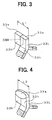
- Fig. 4 is a perspective view illustrating segment ends after being welded or a joint of winding of the conductor segments;
- Fig. 5 is a plan view of a stator viewed from above coil ends;
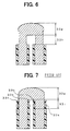
- Fig. 6 is a cross-sectional view illustrating a joint of winding of the stator coated with insulation film of the conductor segments;
- Fig. 7 is a cross-sectional side view illustrating a joint of winding of a stator of a prior art;
- Fig. 8 is a side view of a stator winding of the vehicle AC generator according to the preferred embodiment with the joint of windings coated with insulation film;
- Fig. 9 is a perspective view illustrating a conductor segment according to a variation of the preferred embodiment; and
- Fig. 10 is a perspective view illustrating segment ends of the conductor segments according to another variation of the preferred embodiment.
-
- A vehicle AC generator according to a preferred embodiment of the invention is described in detail with reference to the appended drawings.
- As shown in Fig. 1, the
vehicle AC generator 1 according to the preferred embodiment is comprised of arotor 2, astator 3, a pair offrames 4, arectifier unit 5, etc. - The
rotor 2 is comprised of afield coil 8 having a cylindrically wound insulation-film-coated copper wire, a pair ofpole cores 7, each having six craw poles, and a shaft 6. The shaft 6 penetrates thefield coil 8 and the pair of claw poles. The claw poles envelop thefield coil 8 from opposite ends thereof. A mixed-flow-type cooling fan 11 is welded to the front end of thepole core 7 to blow air from the front end in the axial and radial directions. Acentrifugal cooling fan 12 is also welded to the rear end of thepole core 7 to blow air from the rear end in the radially outer direction. - The
stator 3 is comprised of astator core 32, a stator winding 31 that is formed of a plurality ofconductor segments 33 andinsulators 34 that insulates theconductor segments 33 from thestator core 32. Thestator core 32 is a laminate of thin steel sheets that has a plurality of slots formed at the inner surface thereof. The sheet-like insulators 34 are disposed on the inner wall of the slots. Theconductor segments 33 are insulated from the slots by the insulation film coated thereon andinsulators 34.Coil ends 35 of the stator winding 31 are formed from theconductor segments 33 projecting from thestator core 32. - The pair of
frame 4 accommodates therotor 2 and thestator 3. Therotor 2 is supported by the pair offrames 4 to rotate about the shaft 6, and the stator is fixed around thepole core 7 at a gap. The pair offrames 4 hasair discharge windows 42 at portions thereof opposite the coil ends 35 of thestator 3 andair intake windows 41 at axial end portions thereof. - The
rotor 2 of the above-describedvehicle AC generator 1 rotates in a direction when engine torque is transmitted to the pulley 20 via a belt. If field current is supplied to thefield coil 8 of therotor 2 from outside, the claw poles of thepole core 7 are excited so that the stator winding 31 can generate three-phase AC voltage. Thus, DC power is provided at an output terminal of therectifier unit 5. - The stator winding 31 is formed from a plurality of
U-shaped conductor segments 33 that is arranged and connected at the segment ends thereof in a prescribed rule. - As shown in Fig. 2, a pair of the conductor segments 33a and 33b forms a basic unit. A plurality of pairs of the conductor segments 33a and 33b is arranged to form the stator winding 31. Each
U-shaped conductor segments 33 has aturn portion 33c and segment ends 33e. Theturn portion 33c and adjoining inclined portions 33d form one of the rear (counter pulley side) coil ends 35. The segment ends 33e and the adjoining inclined portion 33f form one of the drive-side (pulley side) coil ends 35. - The
conductor segments 33 are connected at the ends 3e thereof by means of TIG (tungsten inert-gas) welding. As shown in Fig.3, the segment ends 33e of the adjoiningconductor segments 33 are brought in contact with each other and a tungsten electrode is put close thereto, thereby melting part of the segment ends, which are solidified again. Thus, as shown in Fig. 4, the raindrop-shape joints of winding 33g are formed. Since each of the joints of winding 33g is melted and formed into such a raindrop-shape, the radial length L2 of the joint of winding 33g after being welded is shorter than the radial length L1 of the two segment ends 33e before being welded. - The stator winding 31, as shown in Fig 2, has two kinds of conductor segments 33a and 33b as a base unit. Therefore, each base unit has two joints of winding, and the joints of winding 33g are aligned in two coaxial rings, as shown in Fig. 5.
- The
conductor segment 33 has an adjoiningbare portion 33h, from which insulating film is removed. Thisbare portion 33h prevents insulation film, which otherwise deteriorates due to heat while the joint of winding 33g is formed by means of the TIG welding, from peeling off or cracking. As shown in Fig. 7, if insulation film is removed from only a minimum area that is necessary for welding,insulation film 33k in the area 33i that adjoins the joint of winding 33g may deteriorate due to welding heat transmitted thereto and peel off or crack. The area of thebare portion 33h is decided according to temperature of the welding and the dimension of the conductor segments, etc. Thebare portion 33h should be formed at a portion of one conductor segment adjoining the joint of winding 33g that does not cross another conductor segment, in order to prevent the conductor segments crossing each other from short-circuiting. - As shown in Figs. 2, 3 and 4, contact surfaces 33M of the joint of winding 33g, opposite
surface 33L that is opposite to thecontact surface 33M andside surface 33N that is on the side of thecontact surface 33M of the joint of winding 33g are preferably flat. Theflat surface 33M stabilizes the weld condition of the joint of winding. Theflat surface 33L provides gaps between the radially adjoining joint of winding 33g and thebare portion 33h or between the bare portion of the radially outermost joint of winding 33g and the inner wall of theframe 4. Theflat surface 33N provides gaps between circumferentially neighboring joints of winding 33g. Thus, the gaps prevent short-circuiting and improve cooling effect and environmental condition. - As shown in Fig. 8, the joints of winding 33g are formed and covered with
insulation resin 36, which have gaps among circumferentially neighboring joints of winding 33g and a top having undulations or concavities-and-convexities. - Thus, because the
conductor segments 33 of the stator winding 31 havebare portions 33h, there is no insulation film to deteriorate due to heat on surfaces of the conductor segments that adjoin the joints of winding 33g. Therefore, electrolyte or other foreign particles will not enter or stay in such deteriorated film. If the joints of winding 33g are coated withadditional insulation resin 36, theresin 36 can readily stick thereto. Thus, the joints of winding 33g can be coated with a small amount of resin, resulting in low cost and good environmental condition. - As the amount of the resin to be used is reduced, the gaps between the adjoining joints of winding 33g can be widened, so that draft resistance of the cooling air can be reduced. Therefore, cooling effect can be increased and foreign particles can be readily discharged from the inside of the pair of
frames 4. Because the radial length of the joint of winding 33g is made shorter than the radial length of the two segment ends 33e, the gaps between two radially neighboring joints of winding 33g and between the outermost joints of winding 33g and the inner wall of the pair offrames 4 around the joints of winding 33g can be increased to thereby preventing short-circuiting. - As shown in Fig. 9, the
U-shaped conductor segments 33 can be substituted byconductor segments 331 that have no turn portion. The number of the conductor segments and the rings thereof can be changed to meet various requirements. - As shown in Fig. 10, cut-out portions are formed at portions of two segment ends 33e' opposite the surfaces in contact with each other, so that the radial length can be further reduced. In this case, gaps between the radially neighboring joints of winding or between the outermost joint of winding and the inner wall of the pair of
frames 4 can be widen further. Thus, short-circuiting can be well prevented, cooling effect and environmental condition can be improved further. - The cross-section of the
bare portion 33h can be made polygonal instead of rectangular. Since the contact surface of the bare portions can be reduced, it is easier for insulation resin to enter between the bare portions. - In the foregoing description of the present invention, the invention has been disclosed with reference to specific embodiments thereof. It will, however, be evident that various modifications and changes may be made to the specific embodiments of the present invention without departing from the scope of the invention as set forth in the appended claims. Accordingly, the description of the present invention is to be regarded in an illustrative, rather than a restrictive, sense.
Claims (8)
- A vehicle rotary electric machine (1) including a rotor (2), a stator (3) having a stator core (32) and a stator winding (31) mounted in said stator core and a frame (4) for supporting said rotor and said stator, characterized in that
said stator winding comprises a plurality of conductor segments (33) coated with insulation film ,
each of said plurality of conductor segments has segment ends (33e) that are circumferentially aligned and form rings,
those of said segment ends that contact each other are welded and form joints of winding (33g), and
each said segment end has a bare surface (33h)that includes said joint of winding and vicinities thereof. - The vehicle rotary electric machine according to claim 1, wherein
said stator winding has gaps formed between said joints of winding that are aligned in said rings. - The vehicle rotary electric machine according to claim 1, wherein
each of said joints of winding is coated with insulation film and forms circumferential undulations. - The vehicle rotary electric machine according to claim 1, wherein
said conductor segments are radially aligned to form a plurality of layers in respective slots, and that
a radial length of each said joint of winding is shorter than a sum of radial length of said conductor segments. - The vehicle rotary electric machine according to claim 1, wherein
said bare portion has a flat surface (33M)at a portion in contact to each other. - The vehicle rotary electric machine according to claim 5, wherein
said bare portion has flat surfaces (33L) opposite said portion in contact with each other. - The vehicle rotary electric machine according to claim 5, wherein
said bare portion has a flat surface (33N)on the side of said portion in contact each other. - The vehicle rotary electric machine according to claim 1, wherein
said bare portion has an approximately polygonal cross-section.
Priority Applications (1)
| Application Number | Priority Date | Filing Date | Title |
|---|---|---|---|
| EP05007125A EP1548914A3 (en) | 2000-11-06 | 2001-11-02 | Stator arrangement of rotary electric machine |
Applications Claiming Priority (2)
| Application Number | Priority Date | Filing Date | Title |
|---|---|---|---|
| JP2000337847 | 2000-11-06 | ||
| JP2000337847 | 2000-11-06 |
Related Child Applications (1)
| Application Number | Title | Priority Date | Filing Date |
|---|---|---|---|
| EP05007125A Division EP1548914A3 (en) | 2000-11-06 | 2001-11-02 | Stator arrangement of rotary electric machine |
Publications (3)
| Publication Number | Publication Date |
|---|---|
| EP1204195A2 true EP1204195A2 (en) | 2002-05-08 |
| EP1204195A3 EP1204195A3 (en) | 2003-04-16 |
| EP1204195B1 EP1204195B1 (en) | 2006-02-01 |
Family
ID=18813160
Family Applications (2)
| Application Number | Title | Priority Date | Filing Date |
|---|---|---|---|
| EP01126142A Expired - Lifetime EP1204195B1 (en) | 2000-11-06 | 2001-11-02 | Stator arrangement of rotary electric machine |
| EP05007125A Withdrawn EP1548914A3 (en) | 2000-11-06 | 2001-11-02 | Stator arrangement of rotary electric machine |
Family Applications After (1)
| Application Number | Title | Priority Date | Filing Date |
|---|---|---|---|
| EP05007125A Withdrawn EP1548914A3 (en) | 2000-11-06 | 2001-11-02 | Stator arrangement of rotary electric machine |
Country Status (4)
| Country | Link |
|---|---|
| US (2) | US6894415B2 (en) |
| EP (2) | EP1204195B1 (en) |
| KR (1) | KR100438350B1 (en) |
| DE (1) | DE60116944T2 (en) |
Cited By (2)
| Publication number | Priority date | Publication date | Assignee | Title |
|---|---|---|---|---|
| CN106685119A (en) * | 2010-08-18 | 2017-05-17 | 雷米技术有限公司 | Conductor insulation arrangement for electric machine |
| WO2019040956A1 (en) * | 2017-08-28 | 2019-03-07 | Miba Aktiengesellschaft | Stator component for an electric machine |
Families Citing this family (29)
| Publication number | Priority date | Publication date | Assignee | Title |
|---|---|---|---|---|
| JP3709823B2 (en) * | 2001-10-05 | 2005-10-26 | 株式会社デンソー | Vehicle alternator |
| JP4501762B2 (en) * | 2005-04-18 | 2010-07-14 | 株式会社デンソー | Vehicle alternator |
| JP4654068B2 (en) * | 2005-05-24 | 2011-03-16 | 日立オートモティブシステムズ株式会社 | Bonded electric wire, method of processing the bonded electric wire, rotating electric machine stator, rotating electric machine stator manufacturing method, and bonded electric wire manufacturing apparatus |
| DE102006019314A1 (en) * | 2006-04-26 | 2007-10-31 | Robert Bosch Gmbh | Stator`s bar winding manufacturing method for e.g. claw pole generator, of motor vehicle, involves forming fusion zone by arrangement of ends of segments at contacting area, and connecting ends in pairs by contactless fusion welding process |
| US20100001609A1 (en) * | 2006-08-15 | 2010-01-07 | Hitachi, Ltd. | Rotating electric machine |
| JP4910572B2 (en) * | 2006-08-30 | 2012-04-04 | 株式会社デンソー | Rotating electric machine for vehicles |
| JP4412330B2 (en) * | 2007-02-09 | 2010-02-10 | 株式会社デンソー | Stator winding of rotating electric machine and method of manufacturing the same |
| US7888836B2 (en) * | 2007-04-11 | 2011-02-15 | Asmo Co., Ltd. | DC motor with improved wiring connections |
| CN101772877B (en) * | 2007-08-03 | 2012-07-25 | 阿尔斯通技术有限公司 | Electric machine, particularly asynchronous three-phase current hydrogenerator |
| US8637771B1 (en) * | 2010-02-26 | 2014-01-28 | Greald W Yankie | Electromotive coil with improved conductor packing ratio |
| JP5432806B2 (en) * | 2010-04-06 | 2014-03-05 | 株式会社デンソー | Rotating electric machine stator and rotating electric machine |
| EP2525475A4 (en) * | 2010-05-26 | 2016-10-12 | Toyota Motor Co Ltd | Stator structure and stator manufacturing method |
| US8487498B2 (en) * | 2010-07-30 | 2013-07-16 | Hamilton Sundstrand Corporation | Multiple conductor winding in stator |
| JP2012139075A (en) * | 2010-12-28 | 2012-07-19 | Hitachi Automotive Systems Ltd | Rotary electric machine |
| US9130430B2 (en) * | 2011-03-18 | 2015-09-08 | Remy Technologies Llc | Electric machine with fully enclosed in-slot conductors |
| US20130033145A1 (en) * | 2011-08-02 | 2013-02-07 | Remy Technologies, Llc | Electric machine module insulation system and method |
| JP5459561B2 (en) * | 2011-08-23 | 2014-04-02 | 株式会社デンソー | Rotating electric machine |
| KR101339410B1 (en) * | 2011-12-02 | 2013-12-06 | 엘지전자 주식회사 | Stator of electric machine, electromotor having the same, and electric vehicle having the electromotor |
| US20130187494A1 (en) * | 2012-01-25 | 2013-07-25 | Remy Technologies, L.L.C. | Stator assembly for an electric machine |
| US8878414B2 (en) * | 2012-08-09 | 2014-11-04 | GM Global Technology Operations LLC | Stator weld joints and methods of forming same |
| JP5860782B2 (en) * | 2012-08-31 | 2016-02-16 | 日立オートモティブシステムズ株式会社 | Rotating electric machine and manufacturing method thereof |
| JP6299723B2 (en) * | 2015-10-23 | 2018-03-28 | トヨタ自動車株式会社 | Stator coil forming method |
| US10063117B2 (en) * | 2016-03-08 | 2018-08-28 | Hitachi Automotive Systems, Ltd. | Dynamo-electric machine with stator having trapezoid shape segmented coil |
| JP6642494B2 (en) * | 2017-03-10 | 2020-02-05 | トヨタ自動車株式会社 | Manufacturing equipment for stators of rotating electric machines |
| DE102017216164A1 (en) | 2017-09-13 | 2019-03-14 | Robert Bosch Gmbh | Rotor of an electric machine |
| US11296584B2 (en) * | 2017-09-20 | 2022-04-05 | Aisin Corporation | Method of manufacturing rotary electric machine armature |
| DE102018218731A1 (en) * | 2018-10-31 | 2020-04-30 | Thyssenkrupp Ag | Stator for an electrical machine and electrical machine |
| KR102618459B1 (en) * | 2019-01-07 | 2023-12-27 | 엘지마그나 이파워트레인 주식회사 | Stator for electric rotating machine |
| JP6848130B1 (en) * | 2020-01-15 | 2021-03-24 | 株式会社東芝 | Stator manufacturing method |
Citations (4)
| Publication number | Priority date | Publication date | Assignee | Title |
|---|---|---|---|---|
| US4309636A (en) * | 1978-08-17 | 1982-01-05 | Siemens Aktiengesellschaft | Insulation caps for stator winding head connections of an electric machine |
| US5729068A (en) * | 1994-11-17 | 1998-03-17 | Asea Brown Boveri Ag | Electric machine with deformable insulation on soldering lugs |
| US5998903A (en) * | 1997-05-26 | 1999-12-07 | Denso Corporation | Alternator for an automotive vehicle |
| EP1041696A1 (en) * | 1999-03-30 | 2000-10-04 | Denso Corporation | Method for manufacturing the stator windings of an electric machine |
Family Cites Families (35)
| Publication number | Priority date | Publication date | Assignee | Title |
|---|---|---|---|---|
| US565647A (en) * | 1896-08-11 | David p | ||
| US693578A (en) * | 1901-01-12 | 1902-02-18 | Henry H Wait | Conductor for electromagnetic induction apparatus. |
| US1822261A (en) * | 1927-06-28 | 1931-09-08 | Vincent G Apple | Bar wound field element |
| US1826295A (en) * | 1928-06-14 | 1931-10-06 | Vincent G Apple | Dynamo electric machine element |
| US3079519A (en) * | 1956-02-29 | 1963-02-26 | Gen Electric | Coil and method of insulating same |
| US3749950A (en) * | 1972-05-23 | 1973-07-31 | Gen Electric | Dynamoelectric machine having enhanced cooling |
| CA1016586A (en) * | 1974-02-18 | 1977-08-30 | Hubert G. Panter | Grounding of outer winding insulation to cores in dynamoelectric machines |
| CH629042A5 (en) * | 1978-06-29 | 1982-03-31 | Bbc Brown Boveri & Cie | TWO- OR MULTILAYER WINDING OF TWISTED PARTIAL LADERS FOR AN ELECTRICAL MACHINE. |
| US4399843A (en) * | 1980-10-20 | 1983-08-23 | Sedgewick Richard D | Zig-zag winding machine |
| JPS57126105A (en) * | 1981-01-29 | 1982-08-05 | Mitsubishi Electric Corp | Insulating coil |
| GB2101525A (en) * | 1981-07-01 | 1983-01-19 | Malcolm Otty | Composite insulation material |
| JPS61221561A (en) * | 1985-03-27 | 1986-10-01 | Nippon Denso Co Ltd | Flat rotary electric machine |
| KR950000799B1 (en) * | 1990-08-15 | 1995-02-02 | 가부시끼가이샤 히다찌세이사꾸쇼 | Motor and the connection of stator winding with lead wire |
| MY109836A (en) * | 1991-04-30 | 1997-08-30 | Kk Sankyo Seiki Seisakusho | Stator of rotating electric machine. |
| US5864193A (en) * | 1993-10-15 | 1999-01-26 | Denso Corporation | Electric rotating machine having improved insulation for an armature coil |
| US5714824A (en) * | 1994-06-23 | 1998-02-03 | Hydro-Quebec | Conductor section for a stator frame of a polyphase dynamoelectric machine |
| JPH1066314A (en) * | 1996-08-14 | 1998-03-06 | Toyota Motor Corp | Manufacture of stator of motor |
| US6229241B1 (en) * | 1997-03-26 | 2001-05-08 | Hitachi, Ltd. | Structure and manufacturing method for motor and stator |
| JP3405280B2 (en) * | 1997-05-26 | 2003-05-12 | 株式会社デンソー | AC generator for vehicles |
| US6137201A (en) * | 1997-05-26 | 2000-10-24 | Denso Corporation | AC generator for vehicles |
| US6124660A (en) * | 1997-05-26 | 2000-09-26 | Denso Corporation | AC generator for vehicles |
| DE69830869T2 (en) * | 1997-05-26 | 2006-05-24 | Denso Corp., Kariya | Alternator for motor vehicles |
| EP0881748B1 (en) * | 1997-05-26 | 2008-10-08 | Denso Corporation | Alternator for vehicle |
| JP3769990B2 (en) * | 1999-08-06 | 2006-04-26 | 株式会社デンソー | Conductor segment bonding type rotating electrical machine and method for manufacturing the same |
| JP3303854B2 (en) * | 1998-09-22 | 2002-07-22 | 株式会社デンソー | Joint wire and joining method |
| JP3250533B2 (en) * | 1998-11-25 | 2002-01-28 | 株式会社デンソー | Stator for vehicle alternator and method of manufacturing the same |
| JP3104700B1 (en) * | 1999-03-30 | 2000-10-30 | 株式会社デンソー | Method and apparatus for joining windings of rotating electric machine |
| JP3508687B2 (en) * | 1999-07-12 | 2004-03-22 | 株式会社デンソー | Rotating electric machine |
| JP3419721B2 (en) * | 1999-12-06 | 2003-06-23 | 三菱電機株式会社 | AC generator for vehicles |
| JP3078288B1 (en) * | 2000-01-25 | 2000-08-21 | 三菱電機株式会社 | AC generator for vehicles |
| DE10103935A1 (en) * | 2000-02-03 | 2001-08-09 | Denso Corp | Stator arrangement of an electric rotating machine for a vehicle |
| JP4014071B2 (en) * | 2000-03-13 | 2007-11-28 | 三菱電機株式会社 | AC generator, winding assembly thereof, and method of manufacturing winding assembly |
| JP2001286082A (en) * | 2000-04-03 | 2001-10-12 | Mitsubishi Electric Corp | Stator of ac generator |
| JP3621635B2 (en) * | 2000-08-10 | 2005-02-16 | 三菱電機株式会社 | Rotating electric machine |
| JP3964116B2 (en) * | 2000-09-12 | 2007-08-22 | 三菱電機株式会社 | Rotating electric machine stator |
-
2001
- 2001-11-02 US US09/985,414 patent/US6894415B2/en not_active Expired - Lifetime
- 2001-11-02 DE DE60116944T patent/DE60116944T2/en not_active Expired - Lifetime
- 2001-11-02 EP EP01126142A patent/EP1204195B1/en not_active Expired - Lifetime
- 2001-11-02 EP EP05007125A patent/EP1548914A3/en not_active Withdrawn
- 2001-11-06 KR KR10-2001-0068738A patent/KR100438350B1/en active IP Right Grant
-
2004
- 2004-11-23 US US10/994,446 patent/US7038346B2/en not_active Expired - Lifetime
Patent Citations (4)
| Publication number | Priority date | Publication date | Assignee | Title |
|---|---|---|---|---|
| US4309636A (en) * | 1978-08-17 | 1982-01-05 | Siemens Aktiengesellschaft | Insulation caps for stator winding head connections of an electric machine |
| US5729068A (en) * | 1994-11-17 | 1998-03-17 | Asea Brown Boveri Ag | Electric machine with deformable insulation on soldering lugs |
| US5998903A (en) * | 1997-05-26 | 1999-12-07 | Denso Corporation | Alternator for an automotive vehicle |
| EP1041696A1 (en) * | 1999-03-30 | 2000-10-04 | Denso Corporation | Method for manufacturing the stator windings of an electric machine |
Cited By (2)
| Publication number | Priority date | Publication date | Assignee | Title |
|---|---|---|---|---|
| CN106685119A (en) * | 2010-08-18 | 2017-05-17 | 雷米技术有限公司 | Conductor insulation arrangement for electric machine |
| WO2019040956A1 (en) * | 2017-08-28 | 2019-03-07 | Miba Aktiengesellschaft | Stator component for an electric machine |
Also Published As
| Publication number | Publication date |
|---|---|
| EP1204195B1 (en) | 2006-02-01 |
| EP1548914A3 (en) | 2010-08-25 |
| KR100438350B1 (en) | 2004-07-02 |
| KR20020035459A (en) | 2002-05-11 |
| US7038346B2 (en) | 2006-05-02 |
| EP1204195A3 (en) | 2003-04-16 |
| DE60116944T2 (en) | 2006-07-27 |
| US20030127934A1 (en) | 2003-07-10 |
| US6894415B2 (en) | 2005-05-17 |
| US20050073209A1 (en) | 2005-04-07 |
| DE60116944D1 (en) | 2006-04-13 |
| EP1548914A2 (en) | 2005-06-29 |
Similar Documents
| Publication | Publication Date | Title |
|---|---|---|
| EP1204195B1 (en) | Stator arrangement of rotary electric machine | |
| JP4910572B2 (en) | Rotating electric machine for vehicles | |
| JP3508687B2 (en) | Rotating electric machine | |
| US6181043B1 (en) | Alternator for vehicle | |
| US6191508B1 (en) | Stator insulation structure of rotary electric machine | |
| US6147432A (en) | AC generator stator for vehicle | |
| US6492757B2 (en) | Stator arrangement of rotary electric machine for vehicle | |
| JP5510709B2 (en) | Rotating electric machine stator | |
| JP2001119883A (en) | Ac generator for vehicle | |
| US20030164656A1 (en) | Stator of vehicle AC generator | |
| JP3709823B2 (en) | Vehicle alternator | |
| US20110163620A1 (en) | Stator for electric rotating machine and manufacturing method of the same | |
| WO2005107040A1 (en) | Electric rotating machine | |
| JP2006271015A (en) | Alternator for vehicle | |
| JP3724951B2 (en) | Vehicle alternator | |
| JP3770263B2 (en) | Manufacturing method of rotating electrical machine | |
| US6617735B2 (en) | Vehicle AC generator | |
| JP4042386B2 (en) | Rotating electric machine for vehicles | |
| EP0923187B2 (en) | Alternator for a vehicle | |
| JP3438606B2 (en) | AC generator for vehicles | |
| JP4042250B2 (en) | AC generator for vehicles | |
| JP3982415B2 (en) | AC generator for vehicles | |
| JP3738772B2 (en) | AC generator for vehicles |
Legal Events
| Date | Code | Title | Description |
|---|---|---|---|
| PUAI | Public reference made under article 153(3) epc to a published international application that has entered the european phase |
Free format text: ORIGINAL CODE: 0009012 |
|
| AK | Designated contracting states |
Kind code of ref document: A2 Designated state(s): AT BE CH CY DE DK ES FI FR GB GR IE IT LI LU MC NL PT SE TR |
|
| AX | Request for extension of the european patent |
Free format text: AL;LT;LV;MK;RO;SI |
|
| PUAL | Search report despatched |
Free format text: ORIGINAL CODE: 0009013 |
|
| AK | Designated contracting states |
Designated state(s): AT BE CH CY DE DK ES FI FR GB GR IE IT LI LU MC NL PT SE TR |
|
| AX | Request for extension of the european patent |
Extension state: AL LT LV MK RO SI |
|
| 17P | Request for examination filed |
Effective date: 20030602 |
|
| AKX | Designation fees paid |
Designated state(s): DE FR GB IT |
|
| 17Q | First examination report despatched |
Effective date: 20041202 |
|
| GRAP | Despatch of communication of intention to grant a patent |
Free format text: ORIGINAL CODE: EPIDOSNIGR1 |
|
| GRAS | Grant fee paid |
Free format text: ORIGINAL CODE: EPIDOSNIGR3 |
|
| GRAA | (expected) grant |
Free format text: ORIGINAL CODE: 0009210 |
|
| AK | Designated contracting states |
Kind code of ref document: B1 Designated state(s): DE FR GB IT |
|
| PG25 | Lapsed in a contracting state [announced via postgrant information from national office to epo] |
Ref country code: IT Free format text: LAPSE BECAUSE OF FAILURE TO SUBMIT A TRANSLATION OF THE DESCRIPTION OR TO PAY THE FEE WITHIN THE PRE;WARNING: LAPSES OF ITALIAN PATENTS WITH EFFECTIVE DATE BEFORE 2007 MAY HAVE OCCURRED AT ANY TIME BEFORE 2007. THE CORRECT EFFECTIVE DATE MAY BE DIFFERENT FROM THE ONE RECORDED.SCRIBED TIME-LIMIT Effective date: 20060201 |
|
| REG | Reference to a national code |
Ref country code: GB Ref legal event code: FG4D |
|
| REF | Corresponds to: |
Ref document number: 60116944 Country of ref document: DE Date of ref document: 20060413 Kind code of ref document: P |
|
| ET | Fr: translation filed | ||
| PLBE | No opposition filed within time limit |
Free format text: ORIGINAL CODE: 0009261 |
|
| STAA | Information on the status of an ep patent application or granted ep patent |
Free format text: STATUS: NO OPPOSITION FILED WITHIN TIME LIMIT |
|
| 26N | No opposition filed |
Effective date: 20061103 |
|
| PGFP | Annual fee paid to national office [announced via postgrant information from national office to epo] |
Ref country code: GB Payment date: 20121031 Year of fee payment: 12 Ref country code: IT Payment date: 20121110 Year of fee payment: 12 |
|
| GBPC | Gb: european patent ceased through non-payment of renewal fee |
Effective date: 20131102 |
|
| PG25 | Lapsed in a contracting state [announced via postgrant information from national office to epo] |
Ref country code: IT Free format text: LAPSE BECAUSE OF NON-PAYMENT OF DUE FEES Effective date: 20131102 |
|
| PG25 | Lapsed in a contracting state [announced via postgrant information from national office to epo] |
Ref country code: GB Free format text: LAPSE BECAUSE OF NON-PAYMENT OF DUE FEES Effective date: 20131102 |
|
| REG | Reference to a national code |
Ref country code: FR Ref legal event code: PLFP Year of fee payment: 15 |
|
| REG | Reference to a national code |
Ref country code: FR Ref legal event code: PLFP Year of fee payment: 16 |
|
| REG | Reference to a national code |
Ref country code: FR Ref legal event code: PLFP Year of fee payment: 17 |
|
| PGFP | Annual fee paid to national office [announced via postgrant information from national office to epo] |
Ref country code: DE Payment date: 20191121 Year of fee payment: 19 |
|
| PGFP | Annual fee paid to national office [announced via postgrant information from national office to epo] |
Ref country code: FR Payment date: 20191120 Year of fee payment: 19 |
|
| REG | Reference to a national code |
Ref country code: DE Ref legal event code: R119 Ref document number: 60116944 Country of ref document: DE |
|
| PG25 | Lapsed in a contracting state [announced via postgrant information from national office to epo] |
Ref country code: FR Free format text: LAPSE BECAUSE OF NON-PAYMENT OF DUE FEES Effective date: 20201130 |
|
| PG25 | Lapsed in a contracting state [announced via postgrant information from national office to epo] |
Ref country code: DE Free format text: LAPSE BECAUSE OF NON-PAYMENT OF DUE FEES Effective date: 20210601 |