-
The present invention concerns in general terms a method for obtaining an
antenna gain function. More particularly, the present invention relates to a method of
obtaining an antenna gain for a base station in a mobile telecommunication system.
It makes it possible to obtain an antenna gain function, in transmission or reception
mode, which is invariant by change of frequency.
-
The formation of beams or the elimination of interfering signals is well known
in the field of narrow-band antenna processing. Both of these use an array of
antennae, generally linear and uniform (that is to say with a constant pitch) and a
signal weighting module. More precisely, if it is wished to form a beam in reception
mode, the signals received by the different antennae are weighted by means of a set
of complex coefficients before being added. Conversely, if it is wished to form a
beam in transmission mode, the signal to be transmitted is weighted by a set of
complex coefficients and the signals thus weighted are transmitted by the different
antennae.
-
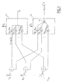
Fig. 1 illustrates a known device for obtaining antenna gain in transmission and
reception mode. The device comprises an array of antennae (100),(101),...,(10N-1), a
transmission weighting module (11) and a reception weighting module (15). The
signals received by the different antennae, (xi ), i=0...N-1 are weighted at
(130),(131)...,(13N-1) by a set of complex coefficients (bui ), i=0,...,N-1 before being
added at (14) in order to give a signal Ru . Conversely, a signal to be transmitted Sd is
weighted at (120),(121)...,(12N-1) by means of a set of complex coefficients (bdi ),
i=0,..,N-1, before being transmitted by the different antennae.
-
If respectively the vector of the signals received and the vector of the
weighting coefficients is denoted x =(x 0,x 1,...,xN -1) T and bu =(bu 0,bu 1 ,...,buN -1) T , it is
possible to write:
Ru = b u x
-
The complex gain (or the complex gain function of the antenna) in reception
mode can be written:
where
eu represents the vector
x corresponding to a plane wave arriving at an
angle of incidence , and
ϕ i =(2πd/λ).i.sin()=(2πdf/c).i..sin()
is the phase shift due to the travelling path length difference between antenna
i and
antenna 0 for a uniform linear array of pitch
d, λ and
f being respectively the
wavelength and the frequency of the plane wave in question. Alternatively,
ϕ i =2πRΔ/λsin(-i )=2πRfΔ/c.sin(- i )
for a circular array where
i is the angle between a reference axis and the normal to
the antenna of index
i,
R the radius of curvature of the array,
Δ is the angular
difference between two consecutive antennae in the array.
-
Likewise the complex gain (or the complex gain function) in transmission
mode can be written:
with the same conventions as those adopted above and where
ed designates the
vector
x corresponding to a plane wave transmitted in the direction .
The weighting vectors in reception and transmission mode respectively will be called
bu and
bd .
-
Clearly, the antenna gain in transmission or reception mode depends on the
frequency of the signal in question. There are however many situations in which the
antenna gain must remain unchanged whatever the frequency of the signal. For
example, in so-called FDD (Frequency Division Duplex) mobile telecommunication
systems, where the frequency used on the downlink, that is to say from the base
station to the mobile station, differs from that used on the uplink. Similarly, in
frequency-hopping radar systems, it is necessary to ensure the invariance of the gain
function, notably in order to aim a transmission or reception beam in a given
direction or to eliminate the interference coming from a given direction, whatever the
frequency used.
-
In more general terms, it is desirable to be able to obtain, for a given signal
frequency, an antenna gain function which is as close as possible, in the sense of a
certain metric, to a reference gain function. The reference gain function can notably
be a gain function obtained at a given frequency which it is sought to approximate to
the greatest possible extent during transmission or reception at another frequency.
-
The aim of the invention is to propose a method for obtaining a gain function
making it possible, for a given signal frequency, to approach a reference gain
function as closely as possible.
-
A subsidiary aim of the invention is to propose a method for best approaching
an antenna gain function obtained at a given frequency when the network is
transmitting or receiving at another frequency.
-
To this end, the invention is defined by a method for obtaining a gain function
by means of an array of antennae and a weighting of the signals received or to be
transmitted by vectors ( b ) of N complex coefficients, referred to as weighting
vectors, N being the number of antennae in the array, according to which, a reference
gain function being given, the said reference gain function is projected orthogonally
onto the sub-space of the gain functions generated by the said weighting vectors of
the space of the gain functions, provided with a norm. A weighting vector generating
the reference gain function thus projected is chosen as the optimum weighting vector.
-
The gain functions are preferably represented by vectors ( G ), referred to as
gain vectors, of M complex samples taken at M distinct angles, defining sampling
directions and belonging to the angular range covered by the array, the space of the
gain functions then being the vector space C M provided with the Euclidian norm. For
a given frequency (f), the reference gain vector is projected onto the vector sub-space
(Imf) of the gain vectors generated by the array operating at the said frequency in
order to obtain the said optimum weighting vector.
-
Advantageously, M is chosen such that M>πN.
-
According to one example embodiment, the sampling angles are distributed
uniformly in an angular range covered by the array.
-
The reference gain vector can be obtained by sampling the reference gain
function filtered by an anti-alias filtering.
-
The gain vectors ( G ) being the transforms by a linear application (h f / s) of C N in
C M weighting vectors of the array and Hf being the matrix, of size MxN, of the said
linear application of a starting base of C N in an arrival base C M, the said optimum
weighting vector, for a given frequency f, is preferably obtained from the reference
gain vector G as b =H + / f. G where H + / f=(H *T / f.H f )-1.H *T / f is the pseudo-inverse matrix of
the matrix Hf and where H *T / f the conjugate transpose of the matrix Hf.
-
The said starting base being that of the vectors e k , k=0,..,N-1, such that
e k=(ek ,0 ,ek, 1,..,ek,N- 1) T with ek,i=exp(j. 2πfd / c.i.sin k ) and k=kπ/N
k=-(N-1)/2,...,0,..,(N-1)/2 and the arrival base being the canonical base, the matrix
Hf then has the components:
Hpq =exp(j(N-1)Ψpq /2). sin(NΨ pq /2)sin(Ψ pq /2)
with
Ψpq=πη(sin(pπ/N)-sin(qπ/M)) and η=f/f0 with f0 =c/2d, d being the pitch of the
array.
-
If the reference gain vector is obtained by sampling the gain function generated
at a first operating frequency f1 of the array by a first weighting vector b1 , the
optimum weighting gain vector for a second frequency f2 is obtained by
b 2 =H + / f2.Hf 1 b 1.
-
The frequency f1 of operation of the array is for example the frequency of an
uplink between a mobile terminal and a base station in a mobile telecommunication
system and the frequency f2 of operation of the array is for example the frequency of
a downlink between the said base station and the said mobile terminal.
-
The characteristics of the invention mentioned above, as well as others, will
emerge more clearly from a reading of the following description given in relation to
the accompanying figures, amongst which:
- Fig. 1 depicts schematically a known device for obtaining an antenna gain
function;
- Fig. 2 depicts schematically a device for obtaining an antenna gain function
according to one example embodiment of the invention.
-
-
A first general idea at the basis of the invention is to best approximate a
reference gain function by virtue of a linear combination of base functions.
-
A second general idea at the basis of the invention is to sample the reference
gain function and to best approximate the series of samples obtained by means of a
linear combination of base vectors.
-
The first embodiment of the invention consists of approximating the reference
gain function by means of a linear combination of base functions.
-
Let h be the linear application from C N (where C is the complex field) to the
vector space F of the complex functions defined on [-π/2,π/2] (or [-π,π]) which
associates with any vector b of complex numbers the function h( b ) such that
h( b )()=G( b ,) where G is a complex gain function in transmission or reception
mode as defined at (2) or (5). C N being a vector space of dimension N on C, the
image of C N by h is a vector sub-space of F of dimension at most equal to N, which
will be denoted Im f to emphasise that the image depends on the frequency f in
question in expression (2) or (5).
-
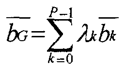
Let
G be a reference complex gain function, the problem is to find the
weighting vector
b such that
h(
b ) is as close as possible to
G in the sense of a
certain metric. For a uniform linear array, the metric corresponding to the scalar
product on
F
and therefore to the norm
is chosen. The case of the circular array can be dealt with in
a similar manner (the chosen norm does not then include the term cos()). The space
F2 of the functions of
F of bounded norm is itself a vector space normed by the
above norm. If
G is an element of
F2, the element of the sub-space Im
f closest to
G
is then the projection of
G onto this sub-space.
-
If the vector sub-space Im
f0 corresponding to the natural frequency (
f0=c/
2d) of
the array is considered, it is possible to demonstrate that the functions
ek(),
k=0, ...,
N-1 defined by:
ek ()=
h(
bk )()=
G(
bk ,), where
bk is the vector of components
bki =exp(
j.2
πki/
N), are
orthogonal. Being
N in number, they therefore form a base of Im
f0 . In more general
terms, it can be shown that, if two vectors
b and
b' are orthogonal, that is to say are
such that
the functions
h(
b ) and
h(
b' ) of Im
f0 are orthogonal.
This is because:
with ϕ()=2π
fd/
c.sin=πηsin where
η=f/
f0≤1, is the ratio of the frequency used at
the maximum frequency
f0=c/
2d, which can resolve the array without ambiguity,
which will be referred to as the natural frequency of the array, and where sinc. is the
cardinal sine function. For
η=1, the terms below the sum signs of the second
member of equation (6) are zero if
i≠i' and therefore the second member is equal to
zero if the vectors
b and
b' are orthogonal.
-
Consider now the general case of a frequency
f≤f0 . Let
ek(),
k=0,...,N-1 be an
orthogonal base of Im
f . By definition,
ek ()=
h(
bk )()=
G(
bk ,) where
bk is a vector of
C N. Consider now a gain function
G of
F2 . It can be projected onto the vectors
ek(). If
λk=G.ek is written, then the vector of
CN ,
is such that
h(
bG )
best approximates the function
G.
-
The second embodiment of the invention consists of approximating a vector of
samples of the reference gain function by means of a linear combination of base
vectors.
-
Let G0() be the antenna gain function obtained without weighting for a linear
uniform array, it is easily shown that:
G 0()=sin(Nϕ/2)sin(ϕ/2) with ϕ=2πfd/c.sin
-
This function has zeros for the values ϕ k =2kπ/N, k integer non-zero such that
ϕ k ∈[-π,π[ that is to say in the directions for which sink=k.c/Nfd, when this
expression is defined. The phase difference between two consecutive zeros of the
gain diagram is constant and is equal to Δϕ=2π/N. The angular difference between
two consecutive zeros of the diagram varies in terms of Arcsin., a function whose
derivative is increasing on [-1,1] and is therefore at a minimum for the angular
difference between the first and second zeros. It is therefore bounded by
Δ min =c/Nfd if N is large enough. It will be assumed that the frequencies used are
less than f0 where f0 is the natural frequency of the array. It can be concluded from
this that the spectrum of the function G0() has a support bounded by 1/Δmin=N/2.
-
In more general terms, let
G() be the antenna gain function obtained by means
of a weighting vector
b .
G can be expressed as the Fourier transform (FT) (in
reception mode) or the inverse Fourier transform (in transmission mode) of the
complex weighting distribution of the antenna, namely:
with
xi=i.d ; this gives:
Gu ()=
B(sin) with
and likewise
Gd ()=
B'(sin) with
The function
b(x) being delimited
by
N.d, the difference between two zeros of the function
B or
B' is at least
λ/
N.d and
therefore even more so
2/
N. Given the increase in the derivative of the function
Arcsin. the minimum difference between two zeros of the function
G is
2/
N. The
function
G therefore has a spectrum delimited by
N/
2.
-
According to the Shannon sampling theorem, it is concluded that it is possible
to reconstitute the function G() if sampling is carried out at a frequency greater than
the Nyquist frequency, i.e. N. In other words, for an angular range [-π/2,π/2], at a
minimum M>π.N samples are necessary, where M is integer. In practice K.N
samples can be taken with K integer, K≥4.
-
For a circular array, it can be shown that 1/Δmin=N and the angular range
being [-π,π], M (M>π.N and M integer) angularly equidistributed samples also
suffice to reconstitute the function G().
-
In the general case of the sampling of any gain function G(), it is necessary to
previously filter G() by means of an anti-aliasing filter before sampling it. It then
suffices to take M samples of the filtered diagram over the whole of the angular
range in order to rebuild the filtered diagram.
-
Let (gk), k=0,..,M-1 be the samples of the complex diagram, possibly filtered
by an anti-aliasing filtering if necessary, that is to say gk =G'(k) where the k are M
angles equidistributed over [-π/2,π/2] or [-π,π] and where it is assumed that G' was
the filtered version of the reference complex diagram.
-
It is now possible to define a linear application, h f s of C N in C M which makes
the vector h f / s( b )= G =(g 0,g 1,..,gM -1) T , where gk =G( b , k ), correspond to any vector b .
The image of C N by h f s is a vector sub-space of C M of dimension at most equal to N,
which will be noted Im f . If a base of C N is chosen, for example the canonical base,
and a base of C M, the linear application h f s can be expressed by a matrix Hf of size
MxN which is at most of rank N.
-
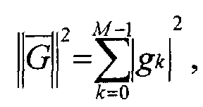
Let
G be any gain vector corresponding to a sampled gain function. The
problem is to find a vector
b such that
h f /
s(
b ) is the closest to
G in the sense of a
certain metric. The Euclidian norm on
C M, namely
will be taken as the
norm. If it exists, the sought-for vector
b is then such that
h f /
s(
b )
=G p where
G p is
the orthogonal projection of the vector
G onto Im
f . If the matrix
Hf is of rank
N, the
sought-for vector
b exists and can be written:
b =H+ f.G
where
H + /
f=(H *
T /
f.H
f )
-1.
H *
T /
f is the pseudo-inverse matrix of the matrix
Hf with
transposed
H *
T /
f the conjugate of the matrix
Hf .
-
In the discrete case as in the continuous case, the reference gain function
(sampled in the discrete case) is projected onto the sub-space generated by the
functions (continuous case) or the vectors (discrete case) associated with the array
weighting vectors.
-
In order to express the matrix
Hf , it is necessary to choose a base of the starting
space and a base of the arrival space. It is possible to choose as a base of
C M the
canonical base and as a base of
C N a base adapted to the description of the plane
waves of frequency
f. Let us consider the distinct vectors
e k ,
k=0,..,
N-1, such that
e k=(
ek ,0,
ek ,1,..,
ek,N -1)
T with
ek,i =exp(
j. 2π
fd / c
.i.sin
k )=exp(
jπ.η.i.sin
k ) with η=
f/
f0 and
where the
k belong to the interval [-π/2,π/2]. The vectors
e k are the weighting
vectors of the array making it possible to form beams in the directions
k . The
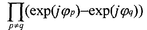
vectors
e k form a base if the determinant of the coordinates of the
e k in the
canonical base of
C N is non-zero. This determinant is a Vandermonde determinant
which is equal to
with ϕ
k =πηsin
k . This determinant is
equal to zero if and only if there are two angles
p and
q such that sin
p -sin
q =2/η.
In other words, for
η<1 the
N vectors
e k always form a base, and for
η=1 only the
case
p =
-q = π/2 is excluded. The directions can, for example, be chosen so as to
be equidistributed, that is to say such that
k=kπ/
N with
k=-(
N-1)/2,...,0,..,(
N-1)/2. In this case, the matrix
Hf has as its components:
or:
with
Ψpq=πη(sin(
pπ/
N)-sin(
qπ/
M))
-
Alternatively, it is possible to choose as a starting base another base adapted to
the frequency f, the one formed by the vectors e'k , such that e'k,i =exp(jπ.η.i.sin k )
with sin k =2k/ηN and k=-(N-1)/2,...,0,..,(N-1)/2. These vectors exist if
|sin k |≤1, ∀k, that is to say for η>1-1/N and in this case the vectors e'k form a base
which has the advantage of being orthogonal.
-
Alternatively, it is possible to choose as a starting base the canonical base of
CN , which has the advantage of not depending on the frequency. In this case, the
matrix H'f expressed in this base is written:
H'f = Hf.T -1
where T is the matrix of the coordinates of e k in the canonical base, that is to
say Tpp '=exp(jπpsin(p'/N)). It was seen above that this matrix had a non-zero
Vandermonde determinant and was consequently invertible.
-
Whatever the chosen base, consider now a gain function obtained at a first
frequency f1, f1≤f0 and G 1 =h f1 / s( b 1 ) the vector of the samples associated with this gain
function. Let there be a second working frequency f2 , f2≤f0 . G 1 belonging to C M, if
the matrix Hf2 is of rank N, it is possible to find a vector b 2 such that h f2 / s( b 2 ) is the
projection of h f1 / s( b 1 ) onto Imf2 . The vector b 2 is obtained by means of the matrix
equation:
b2 =H + f2.Hf 1. b 1
-
This equation makes it possible in particular to obtain, at a second working
frequency, a sampled gain diagram which is as close to possible to the one, referred
to as the reference one, obtained at a first working frequency.
-
Equation (11) advantageously applies to the array of a base station in a mobile
telecommunication system operating in FDD. Equation (10) makes it possible to
directly obtain the weighting vector to be applied for the "downlink" transmission at
a frequency fd on the weighting vector relating to the "uplink" transmission at a
frequency fu . For the paired frequencies fd and fu , it is then possible to write:
bd =H + d .Hu. bu
-
The base station can thus direct transmission beams to the mobile terminals
using a gain function optimised for the reception of the signals transmitted by these
terminals.
-
Fig. 2 depicts an example of an embodiment implementing the second
embodiment. The device comprises a transmission weighting module (31) and a
reception weighting module (35) with a structure identical to that of the modules (11)
and (15) respectively. The module (35) is associated with a module (36) supplying
the complex coefficients for the formation of reception beams and/or the elimination
of signals in the interference directions. The module (36) determines, in a manner
known per se, a weighting vector bu which maximises the signal received in the
useful direction or directions and minimises it in the interference directions.
Advantageously bu is calculated adaptively from the signals received by the different
antennae. The vector is on the one hand used by the reception weighting module
(35) and on the other hand transmitted to a projection and inversion module (32)
determining the vector bd from equation (12). The vector bd is used for weighting
the signals to be transmitted in the module (31). As seen above, the transmission
gain diagram at frequency fu will minimise the difference, in the sense of the
Euclidian distance, between the transmission gain vector Gd and the reception gain
vector Gu .
-
Although the invention has been essentially described, for reasons of simplicity
of presentation, in the context of a uniform linear array, it can apply to any type of
antenna array and notably to a circular array.



 is chosen. The case of the circular array can be dealt with in a similar manner (the chosen norm does not then include the term cos()). The space F2 of the functions of F of bounded norm is itself a vector space normed by the above norm. If G is an element of F2, the element of the sub-space Im f closest to G is then the projection of G onto this sub-space.


 and likewise Gd ()=B'(sin) with
 The function b(x) being delimited by N.d, the difference between two zeros of the function B or B' is at least λ/N.d and therefore even more so 2/N. Given the increase in the derivative of the function Arcsin. the minimum difference between two zeros of the function G is 2/N. The function G therefore has a spectrum delimited by N/2.
 with Ψpq=πη(sin(pπ/N)-sin(qπ/M))