EP1204007A2 - Electrostatographic reproduction machine - Google Patents
Electrostatographic reproduction machine Download PDFInfo
- Publication number
- EP1204007A2 EP1204007A2 EP01309230A EP01309230A EP1204007A2 EP 1204007 A2 EP1204007 A2 EP 1204007A2 EP 01309230 A EP01309230 A EP 01309230A EP 01309230 A EP01309230 A EP 01309230A EP 1204007 A2 EP1204007 A2 EP 1204007A2
- Authority
- EP
- European Patent Office
- Prior art keywords
- belt
- toner image
- moving
- roll
- reproduction machine
- Prior art date
- Legal status (The legal status is an assumption and is not a legal conclusion. Google has not performed a legal analysis and makes no representation as to the accuracy of the status listed.)
- Withdrawn
Links
Images

Classifications
-
- G—PHYSICS
- G03—PHOTOGRAPHY; CINEMATOGRAPHY; ANALOGOUS TECHNIQUES USING WAVES OTHER THAN OPTICAL WAVES; ELECTROGRAPHY; HOLOGRAPHY
- G03G—ELECTROGRAPHY; ELECTROPHOTOGRAPHY; MAGNETOGRAPHY
- G03G15/00—Apparatus for electrographic processes using a charge pattern
- G03G15/75—Details relating to xerographic drum, band or plate, e.g. replacing, testing
- G03G15/754—Details relating to xerographic drum, band or plate, e.g. replacing, testing relating to band, e.g. tensioning
- G03G15/755—Details relating to xerographic drum, band or plate, e.g. replacing, testing relating to band, e.g. tensioning for maintaining the lateral alignment of the band
-
- G—PHYSICS
- G03—PHOTOGRAPHY; CINEMATOGRAPHY; ANALOGOUS TECHNIQUES USING WAVES OTHER THAN OPTICAL WAVES; ELECTROGRAPHY; HOLOGRAPHY
- G03G—ELECTROGRAPHY; ELECTROPHOTOGRAPHY; MAGNETOGRAPHY
- G03G2215/00—Apparatus for electrophotographic processes
- G03G2215/00135—Handling of parts of the apparatus
- G03G2215/00139—Belt
- G03G2215/00143—Meandering prevention
-
- G—PHYSICS
- G03—PHOTOGRAPHY; CINEMATOGRAPHY; ANALOGOUS TECHNIQUES USING WAVES OTHER THAN OPTICAL WAVES; ELECTROGRAPHY; HOLOGRAPHY
- G03G—ELECTROGRAPHY; ELECTROPHOTOGRAPHY; MAGNETOGRAPHY
- G03G2215/00—Apparatus for electrophotographic processes
- G03G2215/01—Apparatus for electrophotographic processes for producing multicoloured copies
- G03G2215/0167—Apparatus for electrophotographic processes for producing multicoloured copies single electrographic recording member
- G03G2215/017—Apparatus for electrophotographic processes for producing multicoloured copies single electrographic recording member single rotation of recording member to produce multicoloured copy
Definitions
- a typical electrophotographic or electrostatographic reproduction machine employs a photoconductive member that is charged to a substantially uniform potential so as to sensitize the surface thereof.
- the charged portion of the photoconductive member is exposed to a light image of an original document being reproduced. Exposure of the charged photoconductive member selectively dissipates the charge thereon in the irradiated areas to record an electrostatic latent image on the photoconductive member corresponding to the informational areas contained within the original document.
- the latent image is developed by bringing a developer material into contact therewith.
- the electrostatic latent image is developed with dry developer material comprising carrier granules having toner particles adhering triboelectrically thereto.
- a liquid developer material may be used as well.
- the toner particles are attracted to the latent image, forming a visible powder image on the photoconductive surface.
- the toner powder image is transferred to a sheet. Thereafter, the toner image is heated to permanently fuse it to the sheet.
- the electrostatographic reproduction machine includes a plurality of stations. Each station has a charging device for charging the photoconductive surface, an exposing device for selectively illuminating the charged portions of the photoconductive surface to record an electrostatic latent image thereon, and a developer unit for developing the electrostatic latent image with toner particles. Each developer unit deposits different color toner particles on the respective electrostatic latent image. The images are developed, at least partially in superimposed registration with one another, to form a multi-color toner powder image.
- the resultant multi-color powder image is subsequently transferred to a sheet.
- the transferred multi-color image is then permanently fused to the sheet forming the color print.
- a color electrostatographic reproduction machine used four developer units. These developer units were all disposed on one side of the photoconductive belt with the other side thereof being devoid of developer units.
- a color electrostatographic reproduction machine of this type required an overly long photoconductive belt.
- a photoconductive belt of this type would require eleven, nine-inch pitches to operate at 100 ppm.
- a belt of this length will have very low yields when being made in large quantities.
- the requirement of having all of the developer units or exposure stations on one side of the photoconductive belt is necessary in order to maintain image-on-image registration. Thus, it is highly desirable to reduce the overall height of the electrostatographic reproduction machine while still maintaining the required image-on-image registration.
- US-A-4,998,145 discloses an electrophotographic electrostatographic reproduction machine having a plurality of developer units adjacent one another on one side of the diameter of a photoconductive drum.
- US-A-5,270,769 describes a electrostatographic reproduction machine having a plurality of developer units disposed on one side of a photoconductive belt. A cleaning unit is positioned on the other side of the photoconductive belt. Different colored developed images are transferred to an intermediate belt. The resultant composite multi-color image is then transferred from the intermediate belt to a sheet of support material and fused thereto.
- the photoconductive belt is arranged vertically.
- US-A-5,313,259 discloses a multi-color electrophotographic electrostatographic reproduction machine in which an endless photoconductive belt is vertically oriented.
- the machine includes four groups of stations for printing in cyan, magenta, yellow, and black.
- Each station includes a charged corona generator, a raster output scanning laser assembly, and a developer unit. These stations are positioned on one side of the photoconductive belt with the fourth station being disposed on the other side thereof. Successive different color toner particle images are formed in superimposed registration with one another on the photoconductive belt and transferred to a copy sheet simultaneously. Transfer occurs at the lowermost position of the photoconductive belt.
- the endless photoconductive belt is arranged into two sides or spans (a slack span and a tension span) that are supported vertically, about a drive roll, skid backer bars, a stripper roll, and a steering and tensioning roll.
- the belt has, and is moved in, a generally elliptical configuration that includes a single free major axis.
- an electrostatographic reproduction machine including a media assembly for supplying and moving toner image receiving media passed a toner image transfer device; a fusing apparatus for heating and fusing a toner image on the toner image receiving media; and an imaging assembly for forming and transferring a toner image onto the toner image receiving media.
- the imaging assembly includes an endless photoreceptor belt having an imageable surface for forming the toner image, and a conicity reducing belt support and moving subassembly for supporting and moving the endless photoreceptor belt.
- the conicity reducing belt support and moving subassembly includes (i) a moveable steering roll for moving in a first direction into the endless photoreceptor belt and in a second direction along an inner surface of the endless photoreceptor belt, and (ii) a moveable tensioning roll for moving in a third direction into the endless photoreceptor belt and in a fourth direction along the inner surface of the endless photoreceptor belt, thereby reducing belt conicity and belt wrinkle, and increasing belt lateral registration.
- the electrostatographic reproduction machine of the present invention is illustrated as a single pass multi-color electrostatographic reproduction machine 8.
- the machine 8 includes a frame 9, a media assembly 57 mounted to the frame 9 for supplying and feeding toner image carrying media such as copy sheets 58 through an image transfer station 56, and a fusing apparatus 64 that includes a pressure roll 68 and a heated fuser roll 70 for heating a fusing toner images to recording media 58.
- the machine 8 employs an endless image bearing member or photoconductive belt 10 that has an imageable surface 13 for forming toner images thereon.
- a series of imaging devices as shown (to be described below) are located in image forming relationship with the imageable surface 13 for forming toner images on the surface 13.
- the machine 8 importantly includes a belt conicity reducing assembly in the form of a belt moving and support assembly 100 for supporting and moving the photoconductive belt 10 so as to reduce its conicity, and thus improve belt lateral registration.
- the belt conicity reducing assembly or belt moving and support assembly 100 comprises four (4) dominant rolls that include a drive roll 102, a sheet stripper roll 104, a moveable tensioning roll 106, and a moveable steering roll 108 of a steering assembly 110.
- the belt moving and support assembly 100 also includes a series of skid backer bars 112, as shown.
- the assembly 100 includes two degrees of freedom a first of which is provided by the moveable steering roll 108 which includes a first free hard axis AX1 that allows the steering roll 108 to not only be moved by a tensioning force applied thereto in a first direction B1 into the belt 10, but to also pivot and thus move in a second direction AX1 along the inner surface of the belt 10.
- the second degree of freedom is provided by the tensioning roll 106 which has a second free hard axis AX2 that allows the tensioning roll 106 to not only be moved by a tensioning force applied thereto in a third direction B2 into the belt 10, but to also be translated and thus moved in a fourth direction AX2 along the inner surface of the belt 10.
- the steering roll 108 and the tensioning roll 106 are located strategically within the loop 113 of the belt 10, and the wrap angles 116, 118 about the rolls 108, 106, respectively are determined so as to reduce risk of belt wrinkle and increase belt lateral registration and belt conicity compensation.
- the steering roll 108 and the tensioning roll 106 are mounted such that the first free hard axis AX1 is normal, or at 90 degrees, to a bisectrix B1 (coincident with the first direction) of the first wrap angle 116 of belt 10 about the steering roll 108, and also such that the second free hard axis AX2 is normal, or at 90 degrees, to a bisectrix B2 (coincident with the third direction) of the wrap angle 118 of belt 10 about the tensioning roll 106.
- the tensioning roll 106 thus can be moved along its bisectrix B2 to exert a first belt tensioning force F1 against the belt 10, and also rotated about the axis AX2 to exert a second belt tensioning force F2 against the belt 10 for adjusting the conicity of the belt 10.
- the steering roll 108 can be moved along its bisectrix B1 to exert a third belt tensioning force F3 against the belt 10, and also rotated about the axis AX1 to exert a fourth belt tensioning force F4 against the belt 10 for adjusting the conicity of the belt 10.
- the steering assembly 110 comprises the steering roll 108, a steering yoke member (not shown) and a camming subassembly (not shown), including pivot shaft 124, located at the ends of the yoke member.
- the pivot shaft 124 defines, and is coincident with, a pivot axis P1 of the steering roll 108.
- the pivot axis P1 forms a bias angle 126 with the bisectrix B1 of the wrap angle 116 of belt 10 about steering roll 108.
- the third belt tensioning force F3 exerted along the bisectrix B1 on the steering roll 108 will have a side force F5 that acts on the pivot shaft 124. This side force F5 biases the pivot shaft 124 and removes undesirable free play caused by clearance between the pivot shaft and its bearings (not shown).
- the tensioning roll 106 with its free hard axis AX2 is located between the stripper roll 104 and the steering roll 108 and sufficiently away from an imaginary straight line 130 between the centers of the steering and stripper rolls, but only to an extent that still creates a belt wrap angle 116 of greater than 90 degrees about the steering roll.
- the belt 10 is arranged in a generally vertical orientation and is driven by drive roll 102 to advance in the direction of arrow 14. As advance, successive portions of its external and imageable surface 13 are moved sequentially beneath various processing stations formed by the various imaging devices (as shown) disposed about the path of movement thereof.
- the various processing stations include five image recording stations indicated generally by the reference numerals 16, 18, 20, 22, and 24, respectively.
- Image recording station 16 includes a charging device 26 and an exposure device 28.
- the charging device 26 is a corona generator that charges the exterior surface 13 of photoconductive belt 10 to a relatively high, substantially uniform potential. After the exterior surface of photoconductive belt 10 is charged, the charged portion thereof advances to the exposure device 28.
- the exposure device 28 for example is a raster output scanner (ROS), which illuminates the charged portion of the exterior surface of photoconductive belt 10 to record a first electrostatic latent image thereon. Alternatively, a light emitting diode (LED) may be used.
- ROS raster output scanner
- LED light emitting diode
- This first electrostatic latent image is developed by developer unit 30 which deposits toner particles of a selected color on the first electrostatic latent image.
- belt 10 continues to advance in the direction of arrow 14 to image recording station 18.
- Image recording station 18 includes a recharging device and an exposure device.
- the charging device includes a corona generator 32 which recharges the exterior surface of photoconductive belt 10 to a relatively high, substantially uniform potential.
- the exposure device includes a ROS 34 which illuminates the charged portion of the exterior surface of photoconductive belt 10 selectively to record a second electrostatic latent image thereon. This second electrostatic latent image is developed with toner particles by developer unit 36.
- Developer unit 36 deposits toner particles (for example magenta color particles) on the electrostatic latent image. In this way, a magenta toner powder image is formed on the exterior surface of photoconductive belt 10. After the magenta toner powder image has been developed on the exterior surface of photoconductive belt 10, photoconductive belt 10 continues to advance in the direction of arrow 14 to image recording station 20.
- toner particles for example magenta color particles
- Image recording station 20 includes a charging device and an exposure device.
- the charging device includes corona generator 38, which recharges the photoconductive surface to a relatively high, substantially uniform potential.
- the exposure device includes ROS 40 which illuminates the charged portion of the exterior surface of photoconductive belt 10 to selectively dissipate the charge thereon to record a third electrostatic latent image corresponding to the regions to be developed with yellow toner particles. This third electrostatic latent image is now advanced to the next successive developer unit 42.
- Developer unit 42 deposits yellow toner particles on the exterior surface of photoconductive belt 10 to form a yellow toner powder image thereon. After the third electrostatic latent image has been developed with yellow toner, belt 10 advances in the direction of arrow 14 to the next image recording station 22.
- Image recording station 22 includes a charging device and an exposure device.
- the charging device includes a corona generator 44, which charges the exterior surface of photoconductive belt 10 to a relatively high, substantially uniform potential.
- the exposure device includes ROS 46, which illuminates the charged portion of the exterior surface of photoconductive belt 10 to selectively dissipate the charge on the exterior surface of photoconductive belt 10 to record a fourth electrostatic latent image for development with cyan toner particles. After the fourth electrostatic latent image is recorded on the exterior surface of photoconductive belt 10, photoconductive belt 10 advances this electrostatic latent image to the magenta developer unit 48.
- Cyan developer unit 48 deposits magenta toner particles on the fourth electrostatic latent image. These toner particles may be partially in superimposed registration with the previously formed yellow powder image. After the cyan toner powder image is formed on the exterior surface of photoconductive belt 10, photoconductive belt 10 advances to the next image recording station 24.
- Image recording station 24 includes a charging device and an exposure device.
- the charging device includes corona generator 50 which charges the exterior surface of photoconductive belt 10 to a relatively high, substantially uniform potential.
- the exposure device includes ROS 54, which illuminates the charged portion of the exterior surface of photoconductive belt 10 to selectively discharge those portions of the charged exterior surface of photoconductive belt 10 which are to be developed with black toner particles.
- the fifth electrostatic latent image, to be developed with black toner particles, is advanced to black developer unit 54.
- black toner particles are deposited on the exterior surface of photoconductive belt 10. These black toner particles form a black toner powder image which may be partially or totally in superimposed registration with the previously formed yellow and magenta toner powder images. In this way, a multi-color toner powder image is formed on the exterior surface of photoconductive belt 10. Thereafter, photoconductive belt 10 advances the multi-color toner powder image to a transfer station, indicated generally by the reference numeral 56.
- a receiving medium i.e., paper
- a corona generating device 60 sprays ions onto the back side of the paper. This attracts the developed multi-color toner image from the exterior surface of photoconductive belt 10 to the sheet of paper.
- Stripping assist roller 66 contacts the interior surface of photoconductive belt 10 and provides a sufficiently sharp bend thereat so that the beam strength of the advancing paper strips from photoconductive belt 10.
- a vacuum transport moves the sheet of paper in the direction of arrow 62 to fusing station 64.
- Fusing station 64 includes a heated fuser roller 70 and a back-up roller 68.
- the back-up roller 68 is resiliently urged into engagement with the fuser roller 70 to form a nip through which the sheet of paper passes.
- the toner particles coalesce with one another and bond to the sheet in image configuration, forming a multi-color image thereon.
- the finished sheet is discharged to a finishing station where the sheets are compiled and formed into sets which may be bound to one another. These sets are then advanced to a catch tray for subsequent removal therefrom by the electrostatographic reproduction machine operator.
- multi-color developed image has been disclosed as being transferred to paper, it may be transferred to an intermediate member, such as a belt or drum, and then subsequently transferred and fused to the paper.
- an intermediate member such as a belt or drum
- toner powder images and toner particles have been disclosed herein, one skilled in the art will appreciate that a liquid developer material employing toner particles in a liquid carrier may also be used.
- an electrostatographic reproduction machine including a media assembly for supplying and moving toner image receiving media passed a toner image transfer device; a fusing apparatus for heating and fusing a toner image on the toner image receiving media; and an imaging assembly for forming and transferring a toner image onto the toner image receiving media.
- the imaging assembly includes an endless photoreceptor belt having an imageable surface for forming the toner image, and a conicity reducing belt support and moving subassembly for supporting and moving the endless photoreceptor belt.
- the conicity reducing belt support and moving subassembly includes (i) a moveable steering roll for moving in a first direction into the endless photoreceptor belt and in a second direction along an inner surface of the endless photoreceptor belt, and (ii) a moveable tensioning roll for moving in a third direction into the endless photoreceptor belt and in a fourth direction along the inner surface of the endless photoreceptor belt, thereby reducing belt conicity and belt wrinkle, and increasing belt lateral registration.
Landscapes
- Physics & Mathematics (AREA)
- General Physics & Mathematics (AREA)
- Electrostatic Charge, Transfer And Separation In Electrography (AREA)
- Electrophotography Configuration And Component (AREA)
- Color Electrophotography (AREA)
- Discharging, Photosensitive Material Shape In Electrophotography (AREA)
Abstract
Description
- A typical electrophotographic or electrostatographic reproduction machine employs a photoconductive member that is charged to a substantially uniform potential so as to sensitize the surface thereof. The charged portion of the photoconductive member is exposed to a light image of an original document being reproduced. Exposure of the charged photoconductive member selectively dissipates the charge thereon in the irradiated areas to record an electrostatic latent image on the photoconductive member corresponding to the informational areas contained within the original document.
- After the electrostatic latent image is recorded on the photoconductive member, the latent image is developed by bringing a developer material into contact therewith. Generally, the electrostatic latent image is developed with dry developer material comprising carrier granules having toner particles adhering triboelectrically thereto. However, a liquid developer material may be used as well. The toner particles are attracted to the latent image, forming a visible powder image on the photoconductive surface. After the electrostatic latent image is developed with the toner particles, the toner powder image is transferred to a sheet. Thereafter, the toner image is heated to permanently fuse it to the sheet.
- It is highly desirable to use an electrostatographic reproduction machine of this type to produce color prints. In order to produce a color print, the electrostatographic reproduction machine includes a plurality of stations. Each station has a charging device for charging the photoconductive surface, an exposing device for selectively illuminating the charged portions of the photoconductive surface to record an electrostatic latent image thereon, and a developer unit for developing the electrostatic latent image with toner particles. Each developer unit deposits different color toner particles on the respective electrostatic latent image. The images are developed, at least partially in superimposed registration with one another, to form a multi-color toner powder image.
- The resultant multi-color powder image is subsequently transferred to a sheet. The transferred multi-color image is then permanently fused to the sheet forming the color print. Hereinbefore, a color electrostatographic reproduction machine used four developer units. These developer units were all disposed on one side of the photoconductive belt with the other side thereof being devoid of developer units. A color electrostatographic reproduction machine of this type required an overly long photoconductive belt. A photoconductive belt of this type would require eleven, nine-inch pitches to operate at 100 ppm. A belt of this length will have very low yields when being made in large quantities. In addition, this results in an overly tall electrostatographic reproduction machine when the photoconductive belt is arranged with the major axis aligned vertically. The requirement of having all of the developer units or exposure stations on one side of the photoconductive belt is necessary in order to maintain image-on-image registration. Thus, it is highly desirable to reduce the overall height of the electrostatographic reproduction machine while still maintaining the required image-on-image registration.
- Various different architectures for multi-color electrostatographic reproduction machines have heretofore been employed. For example, US-A-4,998,145 discloses an electrophotographic electrostatographic reproduction machine having a plurality of developer units adjacent one another on one side of the diameter of a photoconductive drum.
- US-A-5,270,769 describes a electrostatographic reproduction machine having a plurality of developer units disposed on one side of a photoconductive belt. A cleaning unit is positioned on the other side of the photoconductive belt. Different colored developed images are transferred to an intermediate belt. The resultant composite multi-color image is then transferred from the intermediate belt to a sheet of support material and fused thereto. The photoconductive belt is arranged vertically.
- US-A-5,313,259 discloses a multi-color electrophotographic electrostatographic reproduction machine in which an endless photoconductive belt is vertically oriented. The machine includes four groups of stations for printing in cyan, magenta, yellow, and black. Each station includes a charged corona generator, a raster output scanning laser assembly, and a developer unit. These stations are positioned on one side of the photoconductive belt with the fourth station being disposed on the other side thereof. Successive different color toner particle images are formed in superimposed registration with one another on the photoconductive belt and transferred to a copy sheet simultaneously. Transfer occurs at the lowermost position of the photoconductive belt.
- Typically, in these conventional machine architectures, the endless photoconductive belt is arranged into two sides or spans (a slack span and a tension span) that are supported vertically, about a drive roll, skid backer bars, a stripper roll, and a steering and tensioning roll. As such the belt has, and is moved in, a generally elliptical configuration that includes a single free major axis.
- Unfortunately, when there are many skid backer bars on both the slack side and the tension side of the configuration, the single free major axis of belt movement becomes less responsive to belt conicity. As an undesirable consequence, belt conicity compensation of the architecture is compromised. In addition, when the drive roll pushes the belt towards its slack span, drag on the many skid backer bars produces a stiff tension drive between spans, resulting in belt undesirable shear and belt wrinkle.
- In accordance with one aspect of the present invention, there is provided an electrostatographic reproduction machine including a media assembly for supplying and moving toner image receiving media passed a toner image transfer device; a fusing apparatus for heating and fusing a toner image on the toner image receiving media; and an imaging assembly for forming and transferring a toner image onto the toner image receiving media. The imaging assembly includes an endless photoreceptor belt having an imageable surface for forming the toner image, and a conicity reducing belt support and moving subassembly for supporting and moving the endless photoreceptor belt. The conicity reducing belt support and moving subassembly includes (i) a moveable steering roll for moving in a first direction into the endless photoreceptor belt and in a second direction along an inner surface of the endless photoreceptor belt, and (ii) a moveable tensioning roll for moving in a third direction into the endless photoreceptor belt and in a fourth direction along the inner surface of the endless photoreceptor belt, thereby reducing belt conicity and belt wrinkle, and increasing belt lateral registration.
- A particular embodiment in accordance with this invention will now be described with reference to the accompanying drawings; in which:-
- FIG. 1 is a vertical schematic of an exemplary electrostatographic reproduction machine including the belt conicity reducing support assembly of the present invention;
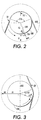
- FIG. 2 is an enlarged schematic illustration of the steering roll movement and forces relative to photoreceptor belt in accordance with the present invention; and
- FIG. 3 is an enlarged schematic illustration of the steering roll movement and forces relative to photoreceptor belt in accordance with the present invention;
-
- Referring now to the drawing, there is shown the electrostatographic reproduction machine of the present invention is illustrated as a single pass multi-color electrostatographic reproduction machine 8. As shown, the machine 8 includes a frame 9, a
media assembly 57 mounted to the frame 9 for supplying and feeding toner image carrying media such ascopy sheets 58 through animage transfer station 56, and afusing apparatus 64 that includes apressure roll 68 and a heatedfuser roll 70 for heating a fusing toner images to recordingmedia 58. - As further shown, the machine 8 employs an endless image bearing member or
photoconductive belt 10 that has animageable surface 13 for forming toner images thereon. A series of imaging devices as shown (to be described below) are located in image forming relationship with theimageable surface 13 for forming toner images on thesurface 13. - The machine 8 importantly includes a belt conicity reducing assembly in the form of a belt moving and
support assembly 100 for supporting and moving thephotoconductive belt 10 so as to reduce its conicity, and thus improve belt lateral registration. As illustrated, the belt conicity reducing assembly or belt moving andsupport assembly 100 comprises four (4) dominant rolls that include adrive roll 102, asheet stripper roll 104, amoveable tensioning roll 106, and amoveable steering roll 108 of a steering assembly 110. The belt moving andsupport assembly 100 also includes a series of skidbacker bars 112, as shown. - The
assembly 100 includes two degrees of freedom a first of which is provided by themoveable steering roll 108 which includes a first free hard axis AX1 that allows thesteering roll 108 to not only be moved by a tensioning force applied thereto in a first direction B1 into thebelt 10, but to also pivot and thus move in a second direction AX1 along the inner surface of thebelt 10. The second degree of freedom is provided by thetensioning roll 106 which has a second free hard axis AX2 that allows thetensioning roll 106 to not only be moved by a tensioning force applied thereto in a third direction B2 into thebelt 10, but to also be translated and thus moved in a fourth direction AX2 along the inner surface of thebelt 10. - The
steering roll 108 and thetensioning roll 106 are located strategically within the loop 113 of thebelt 10, and thewrap angles 116, 118 about therolls steering roll 108 and thetensioning roll 106 are mounted such that the first free hard axis AX1 is normal, or at 90 degrees, to a bisectrix B1 (coincident with the first direction) of the first wrap angle 116 ofbelt 10 about thesteering roll 108, and also such that the second free hard axis AX2 is normal, or at 90 degrees, to a bisectrix B2 (coincident with the third direction) of thewrap angle 118 ofbelt 10 about thetensioning roll 106. - The
tensioning roll 106 thus can be moved along its bisectrix B2 to exert a first belt tensioning force F1 against thebelt 10, and also rotated about the axis AX2 to exert a second belt tensioning force F2 against thebelt 10 for adjusting the conicity of thebelt 10. On the other hand, thesteering roll 108 can be moved along its bisectrix B1 to exert a third belt tensioning force F3 against thebelt 10, and also rotated about the axis AX1 to exert a fourth belt tensioning force F4 against thebelt 10 for adjusting the conicity of thebelt 10. - The steering assembly 110 comprises the
steering roll 108, a steering yoke member (not shown) and a camming subassembly (not shown), includingpivot shaft 124, located at the ends of the yoke member. As mounted, thepivot shaft 124 defines, and is coincident with, a pivot axis P1 of thesteering roll 108. As further shown, the pivot axis P1 forms abias angle 126 with the bisectrix B1 of the wrap angle 116 ofbelt 10 aboutsteering roll 108. As a consequence of thebias angle 126, the third belt tensioning force F3 exerted along the bisectrix B1 on thesteering roll 108, will have a side force F5 that acts on thepivot shaft 124. This side force F5 biases thepivot shaft 124 and removes undesirable free play caused by clearance between the pivot shaft and its bearings (not shown). - As further shown, the
tensioning roll 106 with its free hard axis AX2 is located between thestripper roll 104 and thesteering roll 108 and sufficiently away from an imaginary straight line 130 between the centers of the steering and stripper rolls, but only to an extent that still creates a belt wrap angle 116 of greater than 90 degrees about the steering roll. - Referring again to the drawing, the
belt 10 is arranged in a generally vertical orientation and is driven bydrive roll 102 to advance in the direction ofarrow 14. As advance, successive portions of its external andimageable surface 13 are moved sequentially beneath various processing stations formed by the various imaging devices (as shown) disposed about the path of movement thereof. The various processing stations include five image recording stations indicated generally by thereference numerals - Initially, belt 10 passes through
image recording station 16.Image recording station 16 includes a chargingdevice 26 and anexposure device 28. The chargingdevice 26 is a corona generator that charges theexterior surface 13 ofphotoconductive belt 10 to a relatively high, substantially uniform potential. After the exterior surface ofphotoconductive belt 10 is charged, the charged portion thereof advances to theexposure device 28. Theexposure device 28 for example is a raster output scanner (ROS), which illuminates the charged portion of the exterior surface ofphotoconductive belt 10 to record a first electrostatic latent image thereon. Alternatively, a light emitting diode (LED) may be used. - This first electrostatic latent image is developed by
developer unit 30 which deposits toner particles of a selected color on the first electrostatic latent image. - After the highlight toner image has been developed on the exterior surface of
photoconductive belt 10,belt 10 continues to advance in the direction ofarrow 14 to imagerecording station 18. -
Image recording station 18 includes a recharging device and an exposure device. The charging device includes acorona generator 32 which recharges the exterior surface ofphotoconductive belt 10 to a relatively high, substantially uniform potential. The exposure device includes aROS 34 which illuminates the charged portion of the exterior surface ofphotoconductive belt 10 selectively to record a second electrostatic latent image thereon. This second electrostatic latent image is developed with toner particles bydeveloper unit 36. -
Developer unit 36 deposits toner particles (for example magenta color particles) on the electrostatic latent image. In this way, a magenta toner powder image is formed on the exterior surface ofphotoconductive belt 10. After the magenta toner powder image has been developed on the exterior surface ofphotoconductive belt 10,photoconductive belt 10 continues to advance in the direction ofarrow 14 to imagerecording station 20. -
Image recording station 20 includes a charging device and an exposure device. The charging device includescorona generator 38, which recharges the photoconductive surface to a relatively high, substantially uniform potential. The exposure device includesROS 40 which illuminates the charged portion of the exterior surface ofphotoconductive belt 10 to selectively dissipate the charge thereon to record a third electrostatic latent image corresponding to the regions to be developed with yellow toner particles. This third electrostatic latent image is now advanced to the nextsuccessive developer unit 42. -
Developer unit 42 deposits yellow toner particles on the exterior surface ofphotoconductive belt 10 to form a yellow toner powder image thereon. After the third electrostatic latent image has been developed with yellow toner,belt 10 advances in the direction ofarrow 14 to the nextimage recording station 22. -
Image recording station 22 includes a charging device and an exposure device. The charging device includes acorona generator 44, which charges the exterior surface ofphotoconductive belt 10 to a relatively high, substantially uniform potential. The exposure device includesROS 46, which illuminates the charged portion of the exterior surface ofphotoconductive belt 10 to selectively dissipate the charge on the exterior surface ofphotoconductive belt 10 to record a fourth electrostatic latent image for development with cyan toner particles. After the fourth electrostatic latent image is recorded on the exterior surface ofphotoconductive belt 10,photoconductive belt 10 advances this electrostatic latent image to themagenta developer unit 48. -
Cyan developer unit 48 deposits magenta toner particles on the fourth electrostatic latent image. These toner particles may be partially in superimposed registration with the previously formed yellow powder image. After the cyan toner powder image is formed on the exterior surface ofphotoconductive belt 10,photoconductive belt 10 advances to the nextimage recording station 24. -
Image recording station 24 includes a charging device and an exposure device. The charging device includescorona generator 50 which charges the exterior surface ofphotoconductive belt 10 to a relatively high, substantially uniform potential. The exposure device includesROS 54, which illuminates the charged portion of the exterior surface ofphotoconductive belt 10 to selectively discharge those portions of the charged exterior surface ofphotoconductive belt 10 which are to be developed with black toner particles. The fifth electrostatic latent image, to be developed with black toner particles, is advanced toblack developer unit 54. - At
black developer unit 54, black toner particles are deposited on the exterior surface ofphotoconductive belt 10. These black toner particles form a black toner powder image which may be partially or totally in superimposed registration with the previously formed yellow and magenta toner powder images. In this way, a multi-color toner powder image is formed on the exterior surface ofphotoconductive belt 10. Thereafter,photoconductive belt 10 advances the multi-color toner powder image to a transfer station, indicated generally by thereference numeral 56. - At
transfer station 56, a receiving medium, i.e., paper, is advanced fromstack 58 by sheet feeders and guided to transferstation 56. Attransfer station 56, acorona generating device 60 sprays ions onto the back side of the paper. This attracts the developed multi-color toner image from the exterior surface ofphotoconductive belt 10 to the sheet of paper. Stripping assist roller 66 contacts the interior surface ofphotoconductive belt 10 and provides a sufficiently sharp bend thereat so that the beam strength of the advancing paper strips fromphotoconductive belt 10. A vacuum transport moves the sheet of paper in the direction ofarrow 62 to fusingstation 64. - Fusing
station 64 includes aheated fuser roller 70 and a back-uproller 68. The back-uproller 68 is resiliently urged into engagement with thefuser roller 70 to form a nip through which the sheet of paper passes. In the fusing operation, the toner particles coalesce with one another and bond to the sheet in image configuration, forming a multi-color image thereon. After fusing, the finished sheet is discharged to a finishing station where the sheets are compiled and formed into sets which may be bound to one another. These sets are then advanced to a catch tray for subsequent removal therefrom by the electrostatographic reproduction machine operator. - One skilled in the art will appreciate that while the multi-color developed image has been disclosed as being transferred to paper, it may be transferred to an intermediate member, such as a belt or drum, and then subsequently transferred and fused to the paper. Furthermore, while toner powder images and toner particles have been disclosed herein, one skilled in the art will appreciate that a liquid developer material employing toner particles in a liquid carrier may also be used.
- Invariably, after the multi-color toner powder image has been transferred to the sheet of paper, residual toner particles remain adhering to the exterior surface of
photoconductive belt 10. Thephotoconductive belt 10 moves over isolation roller 78 which isolates the cleaning operation at cleaningstation 72. At cleaningstation 72, the residual toner particles are removed fromphotoconductive belt 10. Thebelt 10 then moves underspots blade 80 to also remove toner particles therefrom. It is, therefore, apparent that there has been provided in accordance with the present invention, an electrostatographic reproduction machine including a media assembly for supplying and moving toner image receiving media passed a toner image transfer device; a fusing apparatus for heating and fusing a toner image on the toner image receiving media; and an imaging assembly for forming and transferring a toner image onto the toner image receiving media. The imaging assembly includes an endless photoreceptor belt having an imageable surface for forming the toner image, and a conicity reducing belt support and moving subassembly for supporting and moving the endless photoreceptor belt. The conicity reducing belt support and moving subassembly includes (i) a moveable steering roll for moving in a first direction into the endless photoreceptor belt and in a second direction along an inner surface of the endless photoreceptor belt, and (ii) a moveable tensioning roll for moving in a third direction into the endless photoreceptor belt and in a fourth direction along the inner surface of the endless photoreceptor belt, thereby reducing belt conicity and belt wrinkle, and increasing belt lateral registration.
Claims (9)
- An electrostatographic reproduction machine comprising(a) a media assembly (56,57,58) for supplying and moving toner image receiving media past a toner image transfer device;(b) a fusing apparatus (64) for heating and fusing a toner image on said toner image receiving media; and(c) an imaging assembly (16,18,20,22,24) for forming and transferring a toner image onto said toner image receiving media, said imaging assembly including the toner image transfer device (60), an endless photoreceptor belt (10) having an imageable surface for forming said toner image, and a conicity reducing belt support and moving subassembly for supporting and moving said endless photoreceptor belt (10), said conicity reducing belt support and moving subassembly (102,104,106,108) including (i) a moveable steering roll (108) for moving in a first direction into said endless photoreceptor belt and in a second direction along an inner surface of said endless photoreceptor belt, and (ii) a moveable tensioning roll (106) for moving in a third direction into said endless photoreceptor belt and in a fourth direction along the inner surface of said endless photoreceptor belt, thereby reducing belt conicity and belt wrinkle, and increasing belt lateral registration.
- An electrostatographic reproduction machine according to claim 1, wherein said endless photoreceptor belt (10) forms a first wrap angle about said tensioning roll (106), and a second wrap angle of greater than 90 degrees about said moveable steering roll (108).
- An electrostatographic reproduction machine according to claim 2, wherein said second direction of movement of said steering roll (108) comprises a first free hard axis (AX1) and is normal to a bisectrix (B1) of said second wrap angle (116) about said steering roll (108).
- An electrostatographic reproduction machine according to claim 2 or 3, wherein said fourth direction of movement of said tensioning roll (106) comprises a second free hard axis (AX2) and is normal to a bisectrix (B2) of said first wrap angle (118) about said tensioning roll (106).
- An electrostatographic reproduction machine according to claim 2, 3 or 4, including a pivot shaft connected to said steering roll (108) and having a pivot axis for moving said steering roll (108) pivotably in said second direction.
- An electrostatographic reproduction machine according to claim 5, wherein said pivot axis forms a biased angle (126) with a bisectrix (B1) of said second wrap angle (116) about said steering roll (108).
- An electrostatographic reproduction machine according to claim 5 or 6, wherein a belt tensioning force, exerted on said steering roll (108) in a direction of the bisectrix (B1) of said second wrap angle (116), has a side component for biasing said pivot shaft.
- An electrostatographic reproduction machine according to any one of the preceding claims, wherein said moveable steering roll (108) exerts a belt tensioning force on said endless photoreceptor belt (10) when moved in said first direction.
- A electrostatographic reproduction machine according to any preceding claim, wherein said moveable tensioning roll (106) exerts a belt tensioning force on said endless photoreceptor belt (10) when moved in said third direction.
Applications Claiming Priority (2)
| Application Number | Priority Date | Filing Date | Title |
|---|---|---|---|
| US708098 | 2000-11-06 | ||
| US09/708,098 US6418286B1 (en) | 2000-11-06 | 2000-11-06 | Electrostatographic reproduction machine having a belt conicity reducing assembly |
Publications (2)
| Publication Number | Publication Date |
|---|---|
| EP1204007A2 true EP1204007A2 (en) | 2002-05-08 |
| EP1204007A3 EP1204007A3 (en) | 2003-06-18 |
Family
ID=24844366
Family Applications (1)
| Application Number | Title | Priority Date | Filing Date |
|---|---|---|---|
| EP01309230A Withdrawn EP1204007A3 (en) | 2000-11-06 | 2001-10-31 | Electrostatographic reproduction machine |
Country Status (6)
| Country | Link |
|---|---|
| US (1) | US6418286B1 (en) |
| EP (1) | EP1204007A3 (en) |
| JP (1) | JP2002156869A (en) |
| BR (1) | BR0105067A (en) |
| CA (1) | CA2360463C (en) |
| MX (1) | MXPA01011204A (en) |
Families Citing this family (3)
| Publication number | Priority date | Publication date | Assignee | Title |
|---|---|---|---|---|
| US8073378B2 (en) * | 2008-05-05 | 2011-12-06 | Xerox Corporation | Xerographic station deskew mechanism |
| US8081901B2 (en) * | 2008-08-11 | 2011-12-20 | Xerox Corporation | Xerographic marking module useful in a xerographic color marking system |
| US7894731B2 (en) * | 2008-08-25 | 2011-02-22 | Xerox Corporation | Method by which an infinite number of colors may be used with a finite number of CCUs |
Citations (2)
| Publication number | Priority date | Publication date | Assignee | Title |
|---|---|---|---|---|
| US4961089A (en) * | 1988-12-27 | 1990-10-02 | Eastman Kodak Company | Method and apparatus for web tracking with predictive control |
| US5200782A (en) * | 1991-11-01 | 1993-04-06 | Xerox Corporation | Disturbance isolation in a belt receptor of a color printer |
Family Cites Families (7)
| Publication number | Priority date | Publication date | Assignee | Title |
|---|---|---|---|---|
| US4174171A (en) * | 1978-07-24 | 1979-11-13 | Xerox Corporation | Belt tracking system |
| JP2630453B2 (en) | 1988-11-25 | 1997-07-16 | コニカ株式会社 | Color image forming equipment |
| US5270769A (en) | 1991-02-21 | 1993-12-14 | Matsushita Electric Industrial Co., Ltd. | Electrophotographic apparatus for formation of color image on intermediate transfer device |
| US5313259A (en) | 1992-12-18 | 1994-05-17 | Xerox Corporation | System and method for operating a multitone imaging apparatus |
| US5479241A (en) * | 1993-01-19 | 1995-12-26 | Xerox Corporation | Method and apparatus for determining and updating a photoreceptor belt steering coefficient in a belt tracking system |
| US5717984A (en) * | 1996-01-11 | 1998-02-10 | Xerox Corporation | Driving, steering and tensioning roll for belt loops |
| US5946533A (en) * | 1998-12-16 | 1999-08-31 | Xerox Corporation | Printing machine architecture |
-
2000
- 2000-11-06 US US09/708,098 patent/US6418286B1/en not_active Expired - Lifetime
-
2001
- 2001-09-26 JP JP2001295120A patent/JP2002156869A/en active Pending
- 2001-10-29 CA CA002360463A patent/CA2360463C/en not_active Expired - Fee Related
- 2001-10-31 EP EP01309230A patent/EP1204007A3/en not_active Withdrawn
- 2001-11-05 MX MXPA01011204A patent/MXPA01011204A/en active IP Right Grant
- 2001-11-06 BR BR0105067-2A patent/BR0105067A/en not_active Application Discontinuation
Patent Citations (2)
| Publication number | Priority date | Publication date | Assignee | Title |
|---|---|---|---|---|
| US4961089A (en) * | 1988-12-27 | 1990-10-02 | Eastman Kodak Company | Method and apparatus for web tracking with predictive control |
| US5200782A (en) * | 1991-11-01 | 1993-04-06 | Xerox Corporation | Disturbance isolation in a belt receptor of a color printer |
Non-Patent Citations (1)
| Title |
|---|
| "IMAGE LOOP CONVEVANCE DEVICE FOR COLOR PRINTER ELECTROPHOTOGRAPHIC ELECTROSTATIC TONED WITH DIFFERENT COLOR TONERS" RESEARCH DISCLOSURE, KENNETH MASON PUBLICATIONS, HAMPSHIRE, GB, no. 370, February 1995 (1995-02), pages 75-77, XP000504459 ISSN: 0374-4353 * |
Also Published As
| Publication number | Publication date |
|---|---|
| CA2360463A1 (en) | 2002-05-06 |
| US6418286B1 (en) | 2002-07-09 |
| JP2002156869A (en) | 2002-05-31 |
| EP1204007A3 (en) | 2003-06-18 |
| CA2360463C (en) | 2004-03-30 |
| BR0105067A (en) | 2002-06-25 |
| MXPA01011204A (en) | 2004-05-21 |
Similar Documents
| Publication | Publication Date | Title |
|---|---|---|
| US8244168B2 (en) | Image forming apparatus with movable transfer device | |
| CA2210570C (en) | Customer replaceable photoreceptor belt module | |
| JP5349999B2 (en) | Process cartridge and image forming apparatus | |
| EP1666979B1 (en) | Electrophotographic image forming apparatus with a separator of recording mediums | |
| JP2010139603A (en) | Image forming apparatus | |
| JP5039296B2 (en) | Image forming apparatus | |
| US6804485B2 (en) | Photoconductive member for asynchronous timing of a printing machine | |
| EP1293845B1 (en) | Composite blade for assisting complete transfer of a toner image from a photosensitive surface | |
| EP0713160B1 (en) | Cleaning apparatus for a moving belt surface | |
| US5946533A (en) | Printing machine architecture | |
| US7561819B2 (en) | Belt cleaning device having cleaning blade for image forming apparatus | |
| US6539194B2 (en) | Image forming apparatus including transfer belt having first and second image transfer surface planes arranged at an angle, and plural image bearing members facing same | |
| CA2360463C (en) | Electrostatographic reproduction machine having a belt conicity reducing assembly | |
| EP0929013B1 (en) | Anti-wrinkle baffle before fusing device | |
| JP3689810B2 (en) | Belt support unit for image forming apparatus | |
| EP0872776B1 (en) | Stalled sheet folding and flattening apparatus in an electrostatographic machine | |
| JP2002062781A (en) | Image-forming apparatus | |
| EP1211569B1 (en) | Torque assist method and apparatus for reducing photoreceptor belt slippage in a printing machine | |
| US7085514B2 (en) | Cleaning device and image forming apparatus equipped with the same | |
| CA2149738C (en) | Printing machine architecture | |
| US7079804B2 (en) | Image forming apparatus | |
| EP0871078B1 (en) | Integral drive roll bearing assembly | |
| JP2017167232A (en) | Tension applying device and image forming apparatus | |
| MXPA99010874A (en) | Machine architecture impres | |
| JPH11126006A (en) | Color image forming device |
Legal Events
| Date | Code | Title | Description |
|---|---|---|---|
| PUAI | Public reference made under article 153(3) epc to a published international application that has entered the european phase |
Free format text: ORIGINAL CODE: 0009012 |
|
| AK | Designated contracting states |
Kind code of ref document: A2 Designated state(s): AT BE CH CY DE DK ES FI FR GB GR IE IT LI LU MC NL PT SE TR |
|
| AX | Request for extension of the european patent |
Free format text: AL;LT;LV;MK;RO;SI |
|
| PUAL | Search report despatched |
Free format text: ORIGINAL CODE: 0009013 |
|
| AK | Designated contracting states |
Designated state(s): AT BE CH CY DE DK ES FI FR GB GR IE IT LI LU MC NL PT SE TR |
|
| AX | Request for extension of the european patent |
Extension state: AL LT LV MK RO SI |
|
| 17P | Request for examination filed |
Effective date: 20031218 |
|
| AKX | Designation fees paid |
Designated state(s): DE FR GB |
|
| 17Q | First examination report despatched |
Effective date: 20050930 |
|
| STAA | Information on the status of an ep patent application or granted ep patent |
Free format text: STATUS: THE APPLICATION IS DEEMED TO BE WITHDRAWN |
|
| 18D | Application deemed to be withdrawn |
Effective date: 20150501 |