EP0872776B1 - Stalled sheet folding and flattening apparatus in an electrostatographic machine - Google Patents
Stalled sheet folding and flattening apparatus in an electrostatographic machine Download PDFInfo
- Publication number
- EP0872776B1 EP0872776B1 EP98104058A EP98104058A EP0872776B1 EP 0872776 B1 EP0872776 B1 EP 0872776B1 EP 98104058 A EP98104058 A EP 98104058A EP 98104058 A EP98104058 A EP 98104058A EP 0872776 B1 EP0872776 B1 EP 0872776B1
- Authority
- EP
- European Patent Office
- Prior art keywords
- sheet
- stalled
- withdrawable
- machine
- path
- Prior art date
- Legal status (The legal status is an assumption and is not a legal conclusion. Google has not performed a legal analysis and makes no representation as to the accuracy of the status listed.)
- Expired - Lifetime
Links
Images

Classifications
-
- G—PHYSICS
- G03—PHOTOGRAPHY; CINEMATOGRAPHY; ANALOGOUS TECHNIQUES USING WAVES OTHER THAN OPTICAL WAVES; ELECTROGRAPHY; HOLOGRAPHY
- G03G—ELECTROGRAPHY; ELECTROPHOTOGRAPHY; MAGNETOGRAPHY
- G03G15/00—Apparatus for electrographic processes using a charge pattern
- G03G15/65—Apparatus which relate to the handling of copy material
Definitions
- This invention relates generally to electrostatographic reproduction machines using copy sheets, and more particularly, to apparatus for folding and flattening a stalled sheet so as to enable its effective removal from a relatively narrow gap between machine components.
- a photoconductive member is charged to a substantially uniform potential so as to sensitize the surface thereof.
- the charged portion of the photoconductive member is exposed to a light image of an original document being reproduced. Exposure of the charged photoconductive member selectively dissipates the charge thereon in the irradiated areas. This process records an electrostatic latent image on the photoconductive member corresponding to the informational areas contained within the original document.
- the latent image is developed by bringing a developer material into contact therewith.
- the developer material is made from toner particles adhering triboelectrically to carrier granules.
- the toner particles are attracted from the carrier granules to the latent image forming a toner powder image on the photoconductive or image bearing member.
- the toner powder image is then transferred at an image transfer station, from the photoconductive member, to a copy substrate such as a copy sheet of paper. Thereafter, heat or some other treatment is applied to the toner particles at a fusing station to permanently fuse and affix the toner powder image to the copy sheet or substrate.
- the copy sheet or substrate typically is fed automatically from a stack supply thereof, along a sheet transport path that includes a sheet registration subassembly, to the image transfer station where the toner image is transferred from the image bearing member onto a first side of the copy sheet.
- the copy sheet is moved along the sheet path to the fusing station of the machine where the toner image is fused and affixed to the copy sheet.
- the sheet path usually includes a sheet inverter, and the copy sheet after leaving the fusing station, is inverted at the inverter and refed to the transfer station in proper orientation for receiving a second toner image on a second side of the copy sheet. In either case, the copy sheet with the fused toner image or images on it is then forwarded to an output tray or finishing station.
- High quality output copies typically require proper and high quality registration of the toner image or images on the copy sheet.
- the copy sheet must be transported in a timed and registered manner to the sheet registration subassembly and to the transfer station each time, and sheet drive mechanisms along the sheet path have to function without slippage.
- Presence and proximity sensors can be used for assisting the achievement of such proper and timed registration of each copy sheet.
- any failure of a copy sheet being transported along the sheet path to activate any of the above sensors at a control point, in time or space usually registers as a machine error. Detection of such an error usually results a copy sheet stall or jam along the sheet path, as well as in a machine shutdown, and in a call or alert for an operator to remove or clear the stalled or jammed copy sheet, wherever it may be, along the sheet transport path.
- drawers in sheet handling machines are often favored because of the benefits they offer for clearing jammed or stalled sheets contained entirely within the subsystem.
- Such drawer designs are particularly employed for electrostatographic machine subsystems such as fuser and post-fuser sheet inverter subsystems that ordinarily include hidden sheet paths that are hard or unsafe to access.
- the withdrawable drawer or module design of such a subsystem is supported on a portion of the frame of the machine, and is made movable in and out of the machine, relative to other fixed portions or components of the machine. As higher and higher speed machines are made to have a smaller and smaller footprint, the gap or interface between withdrawable subsystems and fixed components are becoming narrower and narrower.
- a stalled sheet folding and flattening apparatus which reduces a sheet, stalled between a withdrawable and a fixed component of a cut sheet handling system of a sheet handling machine, into a shape and size suitably enabling reliable removal of the stalled sheet through a relatively narrow gap between the withdrawable and fixed components of the sheet handling system.
- the stalled sheet folding and flattening apparatus includes a fixed component of the sheet handling system connected to a frame of the machine and having a first section of a sheet path; a withdrawable component of the sheet handling system mounted to the frame, and having a sheet flattening side defining a relatively narrow gap between a fixed surface within the machine and the withdrawable component, and including a second section of the sheet path adjoining the first section of the sheet path; and a sheet folding device mounted to the fixed component.
- the sheet folding device includes a generally U-shaped portion defining a slot and having a sheet contact surface forming a part, of an edge of the first section of the sheet path, for contacting and deflecting into a first fold, an edge of a sheet stalled across an interface between the first and the second sections of the sheet path, when the withdrawable component is being pulled out of the machine.
- the sheet contact surface of the U-shaped portion has a first radius of curvature defining a first concave surface for deflecting and folding the stalled sheet, and a second radius of curvature defining a second surface for guiding the folded sheet out of the slot.
- an electrostatographic reproduction machine 8 is illustrated in which an original document is positioned in a document handler 27 on a raster input scanner (RIS) indicated generally by reference numeral 28.
- the RIS contains document illumination lamps, optics, a mechanical scanning drive and a charge coupled device (CCD) array.
- CCD charge coupled device
- the RIS captures the entire original document and converts it to a series of raster scan lines. This information is transmitted to an electronic subsystem (ESS) which controls a raster output scanner (ROS).
- ESS electronic subsystem
- ROS raster output scanner
- the electrostatographic reproduction machine 8 generally employs a photoconductive belt 10 that is preferably made from a photoconductive material coated on a ground layer, which, in turn, is coated on an anti-curl backing layer.
- Belt 10 moves in the direction of arrow 13 to advance successive portions sequentially through the various processing stations disposed about the path of movement thereof.
- Belt 10 is entrained about stripping roller 14, tensioning roller 16 and drive roller 20. As roller 20 rotates, it advances belt 10 in the direction of arrow 13.
- a corona generating device indicated generally by the reference numeral 22 charges the photoconductive belt 10 to a relatively high, substantially uniform potential.
- a controller or electronic subsystem receives the image signals representing the desired output image and processes these signals to convert them to a continuous tone or greyscale rendition of the image which is transmitted to a modulated output generator, for example the raster output scanner (ROS), indicated generally by reference numeral 30.
- ESS 29 is a self-contained, dedicated minicomputer.
- the image signals transmitted to ESS 29 may originate from a RIS as described above or from a computer, thereby enabling the electrostatographic reproduction machine 8 to serve as a remotely located printer for one or more computers.
- the printer may serve as a dedicated printer for a high-speed computer.
- ROS 30 includes a laser with rotating polygon mirror blocks.
- the ROS will expose the photoconductive belt to record an electrostatic latent image thereon corresponding to the continuous tone image received from ESS 29.
- ROS 30 may employ a linear array of light emitting diodes (LEDs) arranged to illuminate the charged portion of photoconductive belt 10 on a raster-by-raster basis.
- LEDs light emitting diodes
- belt 10 advances the latent image to a development station CC, where toner, in the form of liquid or dry particles, is electrostatically attracted to the latent image using commonly known techniques.
- the latent image attracts toner particles from the carrier granules forming a toner powder image thereon.
- a toner particle dispenser indicated generally by the reference numeral 39, dispenses toner particles into developer housing 40 of developer unit 38.
- sheet feeding apparatus 50 includes a nudger roll 51 which feeds the uppermost sheet of stack 54 to nip 55 formed by feed roll 52 and retard roll 53.
- Feed roll 52 rotates to advance the sheet from stack 54 into vertical transport 56.
- Vertical transport 56 directs the advancing sheet 48 of support material into the registration transport 120 of the invention herein, described in detail below, past image transfer station DD to receive an image from photoreceptor belt 10 in a timed sequence so that the toner powder image formed thereon contacts the advancing sheet 48 at transfer station DD.
- Transfer station DD includes a corona generating device 58 which sprays ions onto the back side of sheet 48. This attracts the toner powder image from photoconductive surface 12 to sheet 48. The sheet is then detached from the photoreceptor by corona generating device 59 which sprays oppositely charged ions onto the back side of sheet 48 to assist in removing the sheet from the photoreceptor. After transfer, sheet 48 continues to move in the direction of arrow 60 by way of belt transport 62 which advances sheet 48 to fusing station FF.
- Fusing station FF As shown, at fusing station FF, a fuser assembly 70 and a single sheet inverter mechanism 82 (to be described in detail below) are mounted removably as a withdrawable module 94 on a common platform 96.
- Fusing station FF includes the fuser assembly indicated generally by the reference numeral 70 which permanently fuses and affixes the transferred toner powder image to the copy sheet.
- fuser assembly 70 includes a heated fuser roller 72 and a pressure roller 74 with the powder image on the copy sheet contacting fuser roller 72. The pressure roller is cammed against the fuser roller to provide the necessary pressure to fix the toner powder image to the copy sheet.
- the fuser roll is internally heated by a quartz lamp (not shown).
- Release agent stored in a reservoir (not shown), is pumped to a metering roll (not shown).
- a trim blade (not shown) trims off the excess release agent.
- the release agent transfers to a donor roll (not shown) and then to the fuser roll 72.
- the sheet passes through fuser or fuser assembly 70 where the image is permanently fixed or fused to the sheet.
- a gate 80 either allows the sheet to move directly through an output nip 86 and via an output path 84 to a finisher or stacker (not shown), or it deflects the sheet into the single sheet inverter 82, from which it then enters a duplex path 88.
- the sheet is either a simplex sheet, or a two-pass duplex sheet on its second pass from the fuser, such sheet will be conveyed via gate 80 directly to output path 84.
- the gate 80 will be positioned so as to deflect that sheet into the inverter 82. From the inverter 82, it is then fed into the duplex path 88, where it is fed to acceleration nip 90 and belt transports 92. There it is recirculated back through transfer station DD and fuser 70 for receiving and permanently fixing the side two image to the backside of that duplex sheet, before it exits via exit path 84.
- sheet jams or sheet stalls do occur with sheets being moved through the fuser assembly 70 to the output path 84, as well as with sheets being moved from the fuser assembly 70 through the inverter 82 and into the duplex path 88.
- a copy sheet stall or jam during either of these two movements ordinarily will result in a temporary and partial machine 8 shutdown, and in a call or alert for an operator to remove or clear the stalled or jammed copy sheet, wherever it may be.
- cleaning station EE may include a rotatably mounted fibrous brush in contact with photoconductive surface 12 to disturb and remove paper fibers, and a cleaning blade to remove the nontransferred toner particles.
- the blade may be configured in either a wiper or doctor position depending on the application.
- a discharge lamp (not shown) floods photoconductive surface 12 with light to dissipate any residual electrostatic charge remaining thereon prior to the charging thereof for the next successive imaging cycle.
- the controller is preferably a programmable microprocessor which can be programmed to provide various controls including for example a comparison count of the copy sheets, the number of documents being recirculated, the number of copy sheets selected by the operator, time delays, jam corrections, etc..
- the control of all of the exemplary systems heretofore described may be accomplished by conventional control switch inputs from the reproduction machine 8 consoles selected by the operator.
- Conventional sheet path sensors or switches may be utilized to keep track of the position of the document and the copy sheets.
- the sheet handling machine 8 has a frame 106 (shown only partially), and a cut sheet handling system comprised for example of subsystems 70, 82, 92 including a sheet path comprised for example of segments 84, 88.
- the machine 8 includes the stalled sheet folding and flattening apparatus 100 in accordance with the present invention, for reducing a sheet 108 stalled between the withdrawable and the fixed components 94, 98 respectively, into a shape and size 110 (FIG. 3) that suitably enables reliable removal of the stalled sheet 108 through even the relatively narrow gap 99 between the withdrawable and fixed components 94, 98.
- the fixed component 98 is preferably a portion of the frame 106 of the machine 8, or it could be any other component of the sheet handling system that is mounted fixedly to the frame 106.
- the fixed frame portion or component 98 includes a first section 112 of the sheet path at the interface between the withdrawable and the fixed components.
- the stalled sheet folding and flattening apparatus 100 also includes a withdrawable component such as the component or module 94, which as shown, is mounted movably on rails 114, 116, to the frame 106.
- the withdrawable component 94 importantly includes a sheet flattening side 118 (FIG.
- the sheet flattening side 118 defines the relatively narrow gap 99 between a fixed surface 122 within the machine 8, and the withdrawable component 94.
- the stalled sheet folding and flattening apparatus 100 as shown, importantly includes a sheet folding device 104 which as illustrated is suitable for mounting to the fixed component or frame portion 98 for deflecting, folding and guiding a stalled sheet being pulled out with the withdrawable component 94, through the narrow gap 99.
- the sheet folding device 104 comprises a generally U-shaped member 124 that includes first and second arm portions 126, 128 respectively, and a base portion 130, that together define a sheet guiding and folding slot 132.
- the slot 132 forms part of the sheet path at the interface between the withdrawable and fixed components of the machine.
- the base portion 130 advantageously has a sheet contact compound surface including a concave inside surface 134 forming, within the fixed component 98, a part of an edge of the first section 112 of the sheet path therethrough.
- the sheet contact compound surface of the U-shaped portion 124 importantly includes a first radius R1 of curvature for defining the concave inside surface 134, and a second radius R2 of curvature for defining a second, and convex inside surface 136 (see FIG. 2).
- the concave surface 134 is useful for contacting and deflecting, towards either side of a sheet, an edge of a portion of a stalled sheet 108 that extends across the interface between the withdrawable and the fixed components 94, 98 respectively, when the withdrawable component 94 is being pulled out of the machine 8.
- first and second arm portions 126, 128 each includes a radius R3 of curvature defining another convex inside surface 138 that each adjoins the surface 136, and together comprise the sides of the slot 132, and part of the first section 112 of the sheet path, for guiding the stalled sheet 108.
- the second section 120 of the sheet path as shown includes a sheet gripping nip 140 for retaining a trail end 142 of a stalled sheet 108 that is being pulled out of the machine 8 by the withdrawable component 94.
- the concave surface 134, and convex surface 136 of the base portion, as well as the convex surface 138 of each arm portion 126, 128 then cooperate with the sheet flattening side 118 of the withdrawable component 94 (as 94 is being pulled out of the machine), to buckle and further fold the extending portion 144 along fold lines F2, and F3 (FIGS. 2 and 3).
- the portion 144 thus is buckled and folded as it is being pulled reliably without a risk of tearing, over the convex surface 136, and into the narrow gap 99 beneath the sheet flattening side or surface 118.
- the first radius R1 of the concave surface be less than one half of an edge to edge dimension W1 of the stalled sheet 108.
- the sheet 108 of course is being moved, lead end, followed by trail end 142, through the sheet path.
- the first radius R1 of the concave surface be less than one third the edge to edge dimension W1.
- the base portion 130 is shown as having a hollow exterior surface, it is understood that the exterior surface thereof can equally be solid, thereby making the base portion 130 resemble a half donut shape that is useful as a convex folding ramp or surface 136 which is part of the slot 132 for sheets moved below the inverter 82.
- the edges 138, 148 of the slot 132 work with the convex donut section surface 136 to fold the portion 144 of the sheet as above.
- the side edge 146 engages the surfaces 134, 136 and is deflected to one side or the other above a point shown by a line LP, thus forming the first fold F1. This creates a buckle and a beginning for a second fold F2.
- this first buckle and second fold line F2 form first. This is due in part to the fact that the portion 144 and its rear or opposite side edge 152 are being lifted out of the slot 132 over the surface 136 as the component 94 continues to be moved out of the machine. Lifting the portion 144 as such causes sheet material between fold lines F2 and F1 to be forced against the surface 136 of the slot 132, resulting in a second buckle that forms in the sheet material between fold lines F2 and F3.
- This second buckle thus begins from the fold line F2 in a zag and opposite direction to a zig direction of sheet movement that resulted in the first fold line F1.
- the convex surface 136 adjoins a flat lip 154 of the sheet folding device 104 that preferably is in the same surface as the fixed surface 122 for cooperating with the side or surface 118 on the withdrawable component 94 to flatten the deflected, buckled and folded sheet portion 144 into the shape and size 110 (FIG. 3).
Description
- This invention relates generally to electrostatographic reproduction machines using copy sheets, and more particularly, to apparatus for folding and flattening a stalled sheet so as to enable its effective removal from a relatively narrow gap between machine components.
- In a typical electrostatographic reproduction process machine, a photoconductive member is charged to a substantially uniform potential so as to sensitize the surface thereof. The charged portion of the photoconductive member is exposed to a light image of an original document being reproduced. Exposure of the charged photoconductive member selectively dissipates the charge thereon in the irradiated areas. This process records an electrostatic latent image on the photoconductive member corresponding to the informational areas contained within the original document.
- After the electrostatic latent image is recorded on the photoconductive member, the latent image is developed by bringing a developer material into contact therewith. Generally, the developer material is made from toner particles adhering triboelectrically to carrier granules. The toner particles are attracted from the carrier granules to the latent image forming a toner powder image on the photoconductive or image bearing member. The toner powder image is then transferred at an image transfer station, from the photoconductive member, to a copy substrate such as a copy sheet of paper. Thereafter, heat or some other treatment is applied to the toner particles at a fusing station to permanently fuse and affix the toner powder image to the copy sheet or substrate.
- The copy sheet or substrate typically is fed automatically from a stack supply thereof, along a sheet transport path that includes a sheet registration subassembly, to the image transfer station where the toner image is transferred from the image bearing member onto a first side of the copy sheet. As discussed above, after such toner image transfer, the copy sheet is moved along the sheet path to the fusing station of the machine where the toner image is fused and affixed to the copy sheet. In machines with duplex copying capability, the sheet path usually includes a sheet inverter, and the copy sheet after leaving the fusing station, is inverted at the inverter and refed to the transfer station in proper orientation for receiving a second toner image on a second side of the copy sheet. In either case, the copy sheet with the fused toner image or images on it is then forwarded to an output tray or finishing station.
- High quality output copies typically require proper and high quality registration of the toner image or images on the copy sheet. To achieve such registration, the copy sheet must be transported in a timed and registered manner to the sheet registration subassembly and to the transfer station each time, and sheet drive mechanisms along the sheet path have to function without slippage. Presence and proximity sensors can be used for assisting the achievement of such proper and timed registration of each copy sheet.
- Typically, any failure of a copy sheet being transported along the sheet path to activate any of the above sensors at a control point, in time or space, usually registers as a machine error. Detection of such an error usually results a copy sheet stall or jam along the sheet path, as well as in a machine shutdown, and in a call or alert for an operator to remove or clear the stalled or jammed copy sheet, wherever it may be, along the sheet transport path.
- "Works in a drawer " sheet handling subsystems in sheet handling machines are often favored because of the benefits they offer for clearing jammed or stalled sheets contained entirely within the subsystem. Such drawer designs are particularly employed for electrostatographic machine subsystems such as fuser and post-fuser sheet inverter subsystems that ordinarily include hidden sheet paths that are hard or unsafe to access. Typically, the withdrawable drawer or module design of such a subsystem is supported on a portion of the frame of the machine, and is made movable in and out of the machine, relative to other fixed portions or components of the machine. As higher and higher speed machines are made to have a smaller and smaller footprint, the gap or interface between withdrawable subsystems and fixed components are becoming narrower and narrower.
- Unfortunately, sheets moving through and across such an interface between a withdrawable module and a fixed portion or component of the machine, can become jammed or stalled across such interface. Where as disclosed, for example in Xerox Disclosure Journal, Vol. 8, No. 4, July/August 1983, there is sufficient open space within the machine above or below the withdrawable component or module, a simple contoured ramp can be used to deflect a loose end of the stalled sheet into such open space. Such a simple ramp however will not work where there is only a narrow gap and no such open space. It also will not work in a case where the stalled sheet is within the grip of a nip at both the withdrawable module side.
- Clearing a stalled or jammed sheet in each of these cases presents very unique problems, which often can include preventing the withdrawable module from being movable in or out of the machine. Ordinarily, when the withdrawable module is prevented from being movable in or out of the machine as such, any further attempts to forcibly free it, usually will result in tearing of a portion of the sheet, or in a more severe jam requiring a complete machine shutdown as well as an expensive technical service call. Therefore to avoid such complete shutdowns, and to keep the machine functioning properly, a sheet stalled or jammed in such an interface must be withdrawn in a manner so as not to tear the sheet and not to leave torn bits and pieces of the sheet in the hidden and inaccessible sheet path.
- There is therefore a need to provide apparatus for reducing a sheet, stalled between a withdrawable and a fixed module of an electrostatographic machine, into a shape and size that enable the stalled sheet to be reliably removed through even a relatively narrow gap between the withdrawable and fixed components of the machine.
- In accordance with the present invention, there is provided a stalled sheet folding and flattening apparatus according to independent claim 1 which reduces a sheet, stalled between a withdrawable and a fixed component of a cut sheet handling system of a sheet handling machine, into a shape and size suitably enabling reliable removal of the stalled sheet through a relatively narrow gap between the withdrawable and fixed components of the sheet handling system. The stalled sheet folding and flattening apparatus includes a fixed component of the sheet handling system connected to a frame of the machine and having a first section of a sheet path; a withdrawable component of the sheet handling system mounted to the frame, and having a sheet flattening side defining a relatively narrow gap between a fixed surface within the machine and the withdrawable component, and including a second section of the sheet path adjoining the first section of the sheet path; and a sheet folding device mounted to the fixed component. The sheet folding device includes a generally U-shaped portion defining a slot and having a sheet contact surface forming a part, of an edge of the first section of the sheet path, for contacting and deflecting into a first fold, an edge of a sheet stalled across an interface between the first and the second sections of the sheet path, when the withdrawable component is being pulled out of the machine. The sheet contact surface of the U-shaped portion has a first radius of curvature defining a first concave surface for deflecting and folding the stalled sheet, and a second radius of curvature defining a second surface for guiding the folded sheet out of the slot.
- Other features of the present invention will become apparent as the following description proceeds and upon reference to the drawings, in which:
- FIG. 1 is a perspective illustration of the stalled sheet folding device of the present invention;
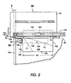
- FIG. 2 is an illustration of the stalled sheet folding and flattening apparatus of the present invention including the sheet folding device of FIG. 1;
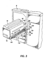
- Figure 3 is a further illustration of the stalled sheet folding and flattening apparatus of the present invention of FIG. 2 showing the withdrawable sheet handling component thereof in a pulled-out or withdrawn position; and
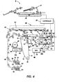
- Figure 4 is a schematic elevational view of a typical electrostatographic reproduction machine including the stalled sheet folding and flattening apparatus of the present invention.
-
- While the present invention will be described in connection with a preferred embodiment thereof, it will be understood that it is not intended to limit the invention to that embodiment. On the contrary, it is intended to cover all alternatives, modifications, and equivalents as may be included within the scope of the invention as defined by the appended claims.
- Referring now to Fig. 4 of the drawings, an
electrostatographic reproduction machine 8 is illustrated in which an original document is positioned in adocument handler 27 on a raster input scanner (RIS) indicated generally byreference numeral 28. The RIS contains document illumination lamps, optics, a mechanical scanning drive and a charge coupled device (CCD) array. The RIS captures the entire original document and converts it to a series of raster scan lines. This information is transmitted to an electronic subsystem (ESS) which controls a raster output scanner (ROS). - As shown, the
electrostatographic reproduction machine 8 generally employs aphotoconductive belt 10 that is preferably made from a photoconductive material coated on a ground layer, which, in turn, is coated on an anti-curl backing layer.Belt 10 moves in the direction ofarrow 13 to advance successive portions sequentially through the various processing stations disposed about the path of movement thereof.Belt 10 is entrained aboutstripping roller 14,tensioning roller 16 anddrive roller 20. Asroller 20 rotates, it advancesbelt 10 in the direction ofarrow 13. - Initially, a portion of the photoconductive surface passes through charging station AA. At charging station AA, a corona generating device indicated generally by the
reference numeral 22 charges thephotoconductive belt 10 to a relatively high, substantially uniform potential. - At an exposure station BB, a controller or electronic subsystem (ESS), indicated generally by
reference numeral 29, receives the image signals representing the desired output image and processes these signals to convert them to a continuous tone or greyscale rendition of the image which is transmitted to a modulated output generator, for example the raster output scanner (ROS), indicated generally byreference numeral 30. Preferably, ESS 29 is a self-contained, dedicated minicomputer. The image signals transmitted toESS 29 may originate from a RIS as described above or from a computer, thereby enabling theelectrostatographic reproduction machine 8 to serve as a remotely located printer for one or more computers. Alternatively, the printer may serve as a dedicated printer for a high-speed computer. - The signals from
ESS 29, corresponding to the continuous tone image desired to be reproduced by thereproduction machine 8, are transmitted toROS 30. ROS 30 includes a laser with rotating polygon mirror blocks. The ROS will expose the photoconductive belt to record an electrostatic latent image thereon corresponding to the continuous tone image received fromESS 29. As an alternative, ROS 30 may employ a linear array of light emitting diodes (LEDs) arranged to illuminate the charged portion ofphotoconductive belt 10 on a raster-by-raster basis. - After the electrostatic latent image has been recorded on
photoconductive surface 12, belt 10 advances the latent image to a development station CC, where toner, in the form of liquid or dry particles, is electrostatically attracted to the latent image using commonly known techniques. The latent image attracts toner particles from the carrier granules forming a toner powder image thereon. As successive electrostatic latent images are developed, toner particles are depleted from the developer material. A toner particle dispenser, indicated generally by the reference numeral 39, dispenses toner particles into developer housing 40 ofdeveloper unit 38. - With continued reference to Figure 4, after the electrostatic latent image is developed, the toner powder image present on
belt 10 advances to transfer station DD. A print sheet 48 is advanced to the transfer station DD by a sheet feeding apparatus, 50. Preferably, sheet feeding apparatus 50 includes anudger roll 51 which feeds the uppermost sheet ofstack 54 to nip 55 formed byfeed roll 52 andretard roll 53.Feed roll 52 rotates to advance the sheet fromstack 54 intovertical transport 56.Vertical transport 56 directs the advancing sheet 48 of support material into theregistration transport 120 of the invention herein, described in detail below, past image transfer station DD to receive an image fromphotoreceptor belt 10 in a timed sequence so that the toner powder image formed thereon contacts the advancing sheet 48 at transfer station DD. Transfer station DD includes acorona generating device 58 which sprays ions onto the back side of sheet 48. This attracts the toner powder image fromphotoconductive surface 12 to sheet 48. The sheet is then detached from the photoreceptor bycorona generating device 59 which sprays oppositely charged ions onto the back side of sheet 48 to assist in removing the sheet from the photoreceptor. After transfer, sheet 48 continues to move in the direction ofarrow 60 by way ofbelt transport 62 which advances sheet 48 to fusing station FF. - As shown, at fusing station FF, a
fuser assembly 70 and a single sheet inverter mechanism 82 (to be described in detail below) are mounted removably as awithdrawable module 94 on acommon platform 96. Fusing station FF as shown includes the fuser assembly indicated generally by thereference numeral 70 which permanently fuses and affixes the transferred toner powder image to the copy sheet. Preferably,fuser assembly 70 includes aheated fuser roller 72 and apressure roller 74 with the powder image on the copy sheet contactingfuser roller 72. The pressure roller is cammed against the fuser roller to provide the necessary pressure to fix the toner powder image to the copy sheet. The fuser roll is internally heated by a quartz lamp (not shown). Release agent, stored in a reservoir (not shown), is pumped to a metering roll (not shown). A trim blade (not shown) trims off the excess release agent. The release agent transfers to a donor roll (not shown) and then to thefuser roll 72. - In a flawless operation with no sheet jams, the sheet passes through fuser or
fuser assembly 70 where the image is permanently fixed or fused to the sheet. After passing throughfuser 70, agate 80 either allows the sheet to move directly through an output nip 86 and via anoutput path 84 to a finisher or stacker (not shown), or it deflects the sheet into thesingle sheet inverter 82, from which it then enters aduplex path 88. Specifically, if the sheet is either a simplex sheet, or a two-pass duplex sheet on its second pass from the fuser, such sheet will be conveyed viagate 80 directly tooutput path 84. However, if the sheet is being duplexed and it is on its first pass from the fuser on its way back for its second pass, then thegate 80 will be positioned so as to deflect that sheet into theinverter 82. From theinverter 82, it is then fed into theduplex path 88, where it is fed to acceleration nip 90 and belt transports 92. There it is recirculated back through transfer station DD andfuser 70 for receiving and permanently fixing the side two image to the backside of that duplex sheet, before it exits viaexit path 84. - However, as is well known, in any
electrostatographic reproduction machine 8 orsheet handling machine 8 including cut sheet handling components or modules, sheets can, and do stall. In some such machine 8s, for example the machine 8 (FIG. 4), withdrawable components such as 94 are mounted adjacent fixedcomponents 98 leaving only a verynarrow gap 99 of about 8mm or less between them, and through which a sheet being moved from one to the other of the two types of components must be removed if it stalls. - For example, in the
machine 8 of FIG. 4, sheet jams or sheet stalls do occur with sheets being moved through thefuser assembly 70 to theoutput path 84, as well as with sheets being moved from thefuser assembly 70 through theinverter 82 and into theduplex path 88. A copy sheet stall or jam during either of these two movements ordinarily will result in a temporary andpartial machine 8 shutdown, and in a call or alert for an operator to remove or clear the stalled or jammed copy sheet, wherever it may be. However, as pointed out above, because of the hidden nature of the sheet path, and the narrowness of thegap 99 through which the stalled sheet must be removed, ordinary attempts to remove stalled sheets frequently result in aggravated jams that end up locking or binding thefuser assembly 70 in place, thus creating acomplete machine 8 shutdown and a major technical service call. In accordance to the present invention however, such aggravated jams are prevented by use of the stalled sheet folding and flatteningapparatus 100 of the present invention ( to be described in detail below). - Still referring to FIG. 4, after the print sheet is separated from
photoconductive surface 12 ofbelt 10, the residual toner/developer and paper fiber particles adhering tophotoconductive surface 12 are removed therefrom at cleaning station EE. As shown, cleaning station EE may include a rotatably mounted fibrous brush in contact withphotoconductive surface 12 to disturb and remove paper fibers, and a cleaning blade to remove the nontransferred toner particles. The blade may be configured in either a wiper or doctor position depending on the application. Subsequent to cleaning, a discharge lamp (not shown) floodsphotoconductive surface 12 with light to dissipate any residual electrostatic charge remaining thereon prior to the charging thereof for the next successive imaging cycle. - As further shown (FIG. 4) the various components and functions of the
machine 8 are regulated by acontroller 29. The controller is preferably a programmable microprocessor which can be programmed to provide various controls including for example a comparison count of the copy sheets, the number of documents being recirculated, the number of copy sheets selected by the operator, time delays, jam corrections, etc.. The control of all of the exemplary systems heretofore described may be accomplished by conventional control switch inputs from thereproduction machine 8 consoles selected by the operator. Conventional sheet path sensors or switches may be utilized to keep track of the position of the document and the copy sheets. - Referring now to FIGS. 1 to 4, the
sheet handling machine 8 has a frame 106 (shown only partially), and a cut sheet handling system comprised for example ofsubsystems segments machine 8 includes the stalled sheet folding and flatteningapparatus 100 in accordance with the present invention, for reducing asheet 108 stalled between the withdrawable and the fixedcomponents sheet 108 through even the relativelynarrow gap 99 between the withdrawable and fixedcomponents - As shown, the fixed
component 98 is preferably a portion of theframe 106 of themachine 8, or it could be any other component of the sheet handling system that is mounted fixedly to theframe 106. In either case, the fixed frame portion orcomponent 98 includes afirst section 112 of the sheet path at the interface between the withdrawable and the fixed components. The stalled sheet folding and flatteningapparatus 100 also includes a withdrawable component such as the component ormodule 94, which as shown, is mounted movably onrails frame 106. Thewithdrawable component 94 importantly includes a sheet flattening side 118 (FIG. 3) which has asecond section 120 of the sheet path located such that thesecond section 120 adjoins thefirst section 112 thereof when thecomponent 94 is pushed back into place within the machine. Thesheet flattening side 118 defines the relativelynarrow gap 99 between afixed surface 122 within themachine 8, and thewithdrawable component 94. - Turning next to FIG. 1 in particular, the stalled sheet folding and flattening
apparatus 100 as shown, importantly includes asheet folding device 104 which as illustrated is suitable for mounting to the fixed component orframe portion 98 for deflecting, folding and guiding a stalled sheet being pulled out with thewithdrawable component 94, through thenarrow gap 99. As further illustrated, thesheet folding device 104 comprises a generallyU-shaped member 124 that includes first andsecond arm portions base portion 130, that together define a sheet guiding andfolding slot 132. When mounted within the machine, theslot 132 forms part of the sheet path at the interface between the withdrawable and fixed components of the machine. Thebase portion 130 advantageously has a sheet contact compound surface including a concaveinside surface 134 forming, within the fixedcomponent 98, a part of an edge of thefirst section 112 of the sheet path therethrough. - The sheet contact compound surface of the
U-shaped portion 124 importantly includes a first radius R1 of curvature for defining the concave insidesurface 134, and a second radius R2 of curvature for defining a second, and convex inside surface 136 (see FIG. 2). Theconcave surface 134 is useful for contacting and deflecting, towards either side of a sheet, an edge of a portion of a stalledsheet 108 that extends across the interface between the withdrawable and the fixedcomponents withdrawable component 94 is being pulled out of themachine 8. As further illustrated, the first andsecond arm portions inside surface 138 that each adjoins thesurface 136, and together comprise the sides of theslot 132, and part of thefirst section 112 of the sheet path, for guiding the stalledsheet 108. As shown, thesecond section 120 of the sheet path as shown (FIGS. 2 and 4) includes a sheet gripping nip 140 for retaining atrail end 142 of a stalledsheet 108 that is being pulled out of themachine 8 by thewithdrawable component 94. - In operation, when a
sheet 108 stalls across the interface between withdrawable and fixedcomponents trail end 142 of the stalled sheet is retained within thenip 140. Aportion 144 of thesheet 108 extends across the interface and hangs loosely through the second section 120 (which in this case is merely a slot or opening through the frame of the machine) of the sheet path as illustrated. As the withdrawable component is being pulled out of the machine on therails side edge 146 of the sheet that faces thebase portion 130 ofdevice 124, is brought into contact with acommon surface line 148 on the concave 134, and convex 136 surfaces of thebase portion 130. Thesurface line 148 contacts and deflects theedge 146 to one side or the other of thesheet 108 within theslot 132, thus creating a first fold F1 in the extendingportion 144 of thesheet 108. - The
concave surface 134, andconvex surface 136 of the base portion, as well as theconvex surface 138 of eacharm portion sheet flattening side 118 of the withdrawable component 94 (as 94 is being pulled out of the machine), to buckle and further fold the extendingportion 144 along fold lines F2, and F3 (FIGS. 2 and 3). Theportion 144 thus is buckled and folded as it is being pulled reliably without a risk of tearing, over theconvex surface 136, and into thenarrow gap 99 beneath the sheet flattening side orsurface 118. Within thegap 99, it is flattened into the shape andsize 110, thereby enabling thesheet 108 to be reliably withdrawn with thewithdrawable component 94, during a jam clearance, through the very narrow gap 99 (FIG. 3). Thesheet 108 as pulled out (FIG. 3) without a tear therein, is then accessible to an operator who can thereafter grasp it, release it and pull it out of thenip 140. - Further in accordance with the present invention, in order to cause the
side edge 146 of the extendingsheet portion 144 to fold at F1, and the remainder thereof to buckle into at least a second fold F2, it is preferable that the first radius R1 of the concave surface be less than one half of an edge to edge dimension W1 of the stalledsheet 108. As illustrated, thesheet 108 of course is being moved, lead end, followed bytrail end 142, through the sheet path. In particular, in order to cause theside edge 146 of the extendingsheet portion 144 to fold at F1, and the remainder thereof to buckle into two additional folds F2, F3, it is preferable that the first radius R1 of the concave surface be less than one third the edge to edge dimension W1. - Although the
base portion 130 is shown as having a hollow exterior surface, it is understood that the exterior surface thereof can equally be solid, thereby making thebase portion 130 resemble a half donut shape that is useful as a convex folding ramp orsurface 136 which is part of theslot 132 for sheets moved below theinverter 82. Theedges slot 132 work with the convexdonut section surface 136 to fold theportion 144 of the sheet as above. As thecomponent 94 starts to move out under an operator pull, theside edge 146 engages thesurfaces portion 144 and its rear oropposite side edge 152 are being lifted out of theslot 132 over thesurface 136 as thecomponent 94 continues to be moved out of the machine. Lifting theportion 144 as such causes sheet material between fold lines F2 and F1 to be forced against thesurface 136 of theslot 132, resulting in a second buckle that forms in the sheet material between fold lines F2 and F3. This second buckle thus begins from the fold line F2 in a zag and opposite direction to a zig direction of sheet movement that resulted in the first fold line F1. - As further illustrated, the
convex surface 136 adjoins aflat lip 154 of thesheet folding device 104 that preferably is in the same surface as the fixedsurface 122 for cooperating with the side orsurface 118 on thewithdrawable component 94 to flatten the deflected, buckled and foldedsheet portion 144 into the shape and size 110 (FIG. 3). - It is, therefore, apparent that there has been provided in accordance with the present invention, a stalled sheet folding and flattening apparatus that fully satisfies the aims and advantages hereinbefore set forth. While this invention has been described in conjunction with a specific embodiment thereof, it is evident that many alternatives, modifications, and variations will be apparent to those skilled in the art. Accordingly, it is intended to embrace all such alternatives, modifications and variations that fall within the scope of the appended claims.
- While the invention herein has been described in the context of an electrostatographic cut sheet using machine, it will be readily apparent that the stalled sheet folding and flattening apparatus thereof can be utilized in any cut sheet handling machine that has a sheet handling system including withdrawable components and fixed components forming interfaces across which sheets can stall.
Claims (2)
- A stalled sheet folding and flattening apparatus (100) usable in a sheet handling machine (8) having a frame (106), and a cut sheet handling system (70, 82, 92) including a sheet path (84, 88), for reducing a sheet (108) stalled between a withdrawable and a fixed component (94, 98) of the sheet handling system into a shape and size suitably enabling reliable removal of the stalled sheet (108) through a relatively narrow gap (99) between the withdrawable and fixed components (94, 98) of the sheet handling system (8), the stalled sheet folding and flattening apparatus (100) comprising:(a) a fixed component (98) of the sheet handling system connected to the machine frame (106) and having a first section (112) of the sheet path;(b) a withdrawable component (94) of the sheet handling system mounted to the frame (106) and having a sheet flattening side (118) defining a relatively narrow gap (99) between a fixed surface within the machine and said withdrawable component (94), and including a second section (120) of the sheet path, said second section (120) adjoining said first section (112) of the sheet path; and(c) a sheet folding device (104) mounted to said fixed component (98) and including a generally U-shaped portion (124) having an inside surface with first and second arm portions (126, 128) and a base portion (130), which define a slot (132) and which can contact a sheet (108), said slot (132) forming a part of said first section (112) of the sheet path, for contacting and deflecting into a first fold (F1), when said withdrawable component (94) is being pulled out of the machine, an edge (146) of a sheet (108) stalled across an interface between said first and said second sections (112, 120) of the sheet path, said contact surface of said U-shaped portion (124) having a first radius (R1) of curvature defining a first concave inside surface (134) for deflecting and folding an edge (146) of the stalled sheet (108), and a second radius (R2) of curvature defining a second convex inside surface (136) for guiding the deflected and folded sheet (108) out of said slot (132).
- The stalled sheet folding device (100) of claim 1, wherein each of said first and second arm portions (126, 128) of said U-shaped member (124) includes a radius (R3) of curvature defining another convex inside surface (138) for guiding a sheet (108) being handled across the interface between the withdrawable and the fixed components (94, 98) of the sheet handling system (8).
Applications Claiming Priority (2)
| Application Number | Priority Date | Filing Date | Title |
|---|---|---|---|
| US837027 | 1997-04-11 | ||
| US08/837,027 US5840003A (en) | 1997-04-11 | 1997-04-11 | Stalled sheet folding and flattening apparatus in an electrostatographic machine |
Publications (3)
| Publication Number | Publication Date |
|---|---|
| EP0872776A2 EP0872776A2 (en) | 1998-10-21 |
| EP0872776A3 EP0872776A3 (en) | 2000-01-26 |
| EP0872776B1 true EP0872776B1 (en) | 2004-05-06 |
Family
ID=25273305
Family Applications (1)
| Application Number | Title | Priority Date | Filing Date |
|---|---|---|---|
| EP98104058A Expired - Lifetime EP0872776B1 (en) | 1997-04-11 | 1998-03-06 | Stalled sheet folding and flattening apparatus in an electrostatographic machine |
Country Status (4)
| Country | Link |
|---|---|
| US (1) | US5840003A (en) |
| EP (1) | EP0872776B1 (en) |
| JP (1) | JPH10329981A (en) |
| DE (1) | DE69823580T2 (en) |
Families Citing this family (7)
| Publication number | Priority date | Publication date | Assignee | Title |
|---|---|---|---|---|
| US6697589B1 (en) | 2001-03-12 | 2004-02-24 | Lexmark International, Inc. | Fuser latch system |
| US6537219B2 (en) * | 2001-04-04 | 2003-03-25 | Koninklijke Philips Electronics N.V. | Static focus ultrasound apparatus and method |
| US6757506B2 (en) | 2002-05-28 | 2004-06-29 | Xerox Corporation | Media clearance member |
| EP1475334A1 (en) * | 2003-05-08 | 2004-11-10 | MASCHINENBAU OPPENWEILER BINDER GmbH & Co. KG | Folding machine with at least one pair of knife shafts |
| JP4811222B2 (en) * | 2006-09-27 | 2011-11-09 | 富士ゼロックス株式会社 | Drawer unit and image forming apparatus |
| US8667392B2 (en) * | 2006-12-12 | 2014-03-04 | Xerox Corporation | Automated submission of folded print job |
| US9221226B2 (en) * | 2012-04-09 | 2015-12-29 | Xerox Corporation | Personalized packaging production system |
Family Cites Families (4)
| Publication number | Priority date | Publication date | Assignee | Title |
|---|---|---|---|---|
| JPH02149861A (en) * | 1988-12-01 | 1990-06-08 | Ricoh Co Ltd | Image forming device |
| JPH03174549A (en) * | 1989-12-04 | 1991-07-29 | Ricoh Co Ltd | Electrophotographic recording device |
| JPH04179979A (en) * | 1990-11-14 | 1992-06-26 | Mita Ind Co Ltd | Structure of transfer drum |
| JP3541488B2 (en) * | 1995-04-14 | 2004-07-14 | 富士ゼロックス株式会社 | Image forming device |
-
1997
- 1997-04-11 US US08/837,027 patent/US5840003A/en not_active Expired - Lifetime
-
1998
- 1998-03-06 DE DE69823580T patent/DE69823580T2/en not_active Expired - Fee Related
- 1998-03-06 EP EP98104058A patent/EP0872776B1/en not_active Expired - Lifetime
- 1998-04-03 JP JP10091735A patent/JPH10329981A/en not_active Withdrawn
Also Published As
| Publication number | Publication date |
|---|---|
| EP0872776A2 (en) | 1998-10-21 |
| DE69823580T2 (en) | 2004-09-16 |
| JPH10329981A (en) | 1998-12-15 |
| DE69823580D1 (en) | 2004-06-09 |
| EP0872776A3 (en) | 2000-01-26 |
| US5840003A (en) | 1998-11-24 |
Similar Documents
| Publication | Publication Date | Title |
|---|---|---|
| US5708924A (en) | Customer replaceable photoreceptor belt module | |
| US6775514B2 (en) | Substrate size monitoring system for use in copier/printers | |
| US5467182A (en) | Sheet transport for high productivity trayless duplex | |
| US5887229A (en) | Photoreceptor shipping installation clip for xerographic customer replaceable unit (CRU) | |
| US5769410A (en) | Lift and drive actuators for feeder CRU | |
| EP0872776B1 (en) | Stalled sheet folding and flattening apparatus in an electrostatographic machine | |
| US5732620A (en) | Stalled sheet pulling and crushing apparatus in an electrostatographic machine | |
| JPH07285701A (en) | Self center-adjustinf type idler assembly with low jamming rate | |
| EP0870707B1 (en) | Jam clearance features for modular-type decurler having continuous bending nip | |
| US20040022554A1 (en) | Drop seal actuator | |
| US6757506B2 (en) | Media clearance member | |
| US6035490A (en) | Cover hinge with integral detent | |
| EP0929013B1 (en) | Anti-wrinkle baffle before fusing device | |
| US5983053A (en) | Non-contacting hybrid jumping developer dirt emission baffle seal | |
| US6167223A (en) | Photoreceptor drive module | |
| KR100306064B1 (en) | Image forming apparatus | |
| US5953565A (en) | Developer backer bar that allows axial misalignment between the backer bar and the developer donor roll | |
| US5649276A (en) | Use of conical drive rolls in a stalled roll registration subsystem to prevent creasing | |
| EP1479633B1 (en) | Sheet copy documents producing machine | |
| EP0871078B1 (en) | Integral drive roll bearing assembly | |
| US5966565A (en) | Composite cleaner seal for electrophotographic machines | |
| EP0855626A2 (en) | Sheet transport apparatus | |
| CA2360463C (en) | Electrostatographic reproduction machine having a belt conicity reducing assembly | |
| US6035161A (en) | Developer backer bar that allows a large amount of photoreceptor wrap with minimal surface contact area for greater axial misalignment | |
| KR100202381B1 (en) | Feeding device of electrographic process |
Legal Events
| Date | Code | Title | Description |
|---|---|---|---|
| PUAI | Public reference made under article 153(3) epc to a published international application that has entered the european phase |
Free format text: ORIGINAL CODE: 0009012 |
|
| AK | Designated contracting states |
Kind code of ref document: A2 Designated state(s): DE FR GB |
|
| PUAL | Search report despatched |
Free format text: ORIGINAL CODE: 0009013 |
|
| AK | Designated contracting states |
Kind code of ref document: A3 Designated state(s): AT BE CH DE DK ES FI FR GB GR IE IT LI LU MC NL PT SE |
|
| 17P | Request for examination filed |
Effective date: 20000726 |
|
| AKX | Designation fees paid |
Free format text: DE FR GB |
|
| 17Q | First examination report despatched |
Effective date: 20020115 |
|
| GRAP | Despatch of communication of intention to grant a patent |
Free format text: ORIGINAL CODE: EPIDOSNIGR1 |
|
| GRAS | Grant fee paid |
Free format text: ORIGINAL CODE: EPIDOSNIGR3 |
|
| GRAA | (expected) grant |
Free format text: ORIGINAL CODE: 0009210 |
|
| AK | Designated contracting states |
Kind code of ref document: B1 Designated state(s): DE FR GB |
|
| REG | Reference to a national code |
Ref country code: GB Ref legal event code: FG4D |
|
| REF | Corresponds to: |
Ref document number: 69823580 Country of ref document: DE Date of ref document: 20040609 Kind code of ref document: P |
|
| REG | Reference to a national code |
Ref country code: GB Ref legal event code: 746 Effective date: 20041130 |
|
| ET | Fr: translation filed | ||
| PLBE | No opposition filed within time limit |
Free format text: ORIGINAL CODE: 0009261 |
|
| STAA | Information on the status of an ep patent application or granted ep patent |
Free format text: STATUS: NO OPPOSITION FILED WITHIN TIME LIMIT |
|
| REG | Reference to a national code |
Ref country code: FR Ref legal event code: D6 |
|
| 26N | No opposition filed |
Effective date: 20050208 |
|
| PGFP | Annual fee paid to national office [announced via postgrant information from national office to epo] |
Ref country code: GB Payment date: 20070228 Year of fee payment: 10 |
|
| PGFP | Annual fee paid to national office [announced via postgrant information from national office to epo] |
Ref country code: DE Payment date: 20070301 Year of fee payment: 10 |
|
| PGFP | Annual fee paid to national office [announced via postgrant information from national office to epo] |
Ref country code: FR Payment date: 20070308 Year of fee payment: 10 |
|
| GBPC | Gb: european patent ceased through non-payment of renewal fee |
Effective date: 20080306 |
|
| REG | Reference to a national code |
Ref country code: FR Ref legal event code: ST Effective date: 20081125 |
|
| PG25 | Lapsed in a contracting state [announced via postgrant information from national office to epo] |
Ref country code: DE Free format text: LAPSE BECAUSE OF NON-PAYMENT OF DUE FEES Effective date: 20081001 |
|
| PG25 | Lapsed in a contracting state [announced via postgrant information from national office to epo] |
Ref country code: FR Free format text: LAPSE BECAUSE OF NON-PAYMENT OF DUE FEES Effective date: 20080331 |
|
| PG25 | Lapsed in a contracting state [announced via postgrant information from national office to epo] |
Ref country code: GB Free format text: LAPSE BECAUSE OF NON-PAYMENT OF DUE FEES Effective date: 20080306 |