EP1203737B1 - Apparatus for loading and unloading of tiles from roller stillages - Google Patents
Apparatus for loading and unloading of tiles from roller stillages Download PDFInfo
- Publication number
- EP1203737B1 EP1203737B1 EP01203866A EP01203866A EP1203737B1 EP 1203737 B1 EP1203737 B1 EP 1203737B1 EP 01203866 A EP01203866 A EP 01203866A EP 01203866 A EP01203866 A EP 01203866A EP 1203737 B1 EP1203737 B1 EP 1203737B1
- Authority
- EP
- European Patent Office
- Prior art keywords
- plane
- tiles
- roller plane
- roller
- stillages
- Prior art date
- Legal status (The legal status is an assumption and is not a legal conclusion. Google has not performed a legal analysis and makes no representation as to the accuracy of the status listed.)
- Expired - Lifetime
Links
Images


Classifications
-
- B—PERFORMING OPERATIONS; TRANSPORTING
- B65—CONVEYING; PACKING; STORING; HANDLING THIN OR FILAMENTARY MATERIAL
- B65G—TRANSPORT OR STORAGE DEVICES, e.g. CONVEYORS FOR LOADING OR TIPPING, SHOP CONVEYOR SYSTEMS OR PNEUMATIC TUBE CONVEYORS
- B65G49/00—Conveying systems characterised by their application for specified purposes not otherwise provided for
- B65G49/05—Conveying systems characterised by their application for specified purposes not otherwise provided for for fragile or damageable materials or articles
- B65G49/08—Conveying systems characterised by their application for specified purposes not otherwise provided for for fragile or damageable materials or articles for ceramic mouldings
- B65G49/085—Conveying systems characterised by their application for specified purposes not otherwise provided for for fragile or damageable materials or articles for ceramic mouldings for loading or unloading racks or similar frames; loading racks therefor
Definitions
- the prior art teaches loaders and unloaders for storing and transporting tiles on roller boxes which operate at the ends of lines and which essentially comprise: a fixed roller plane, supplied with tiles from the line, which tiles are translated and arranged side-by-side so as to form tile layers; a mobile roller plane then transfers the tiles from the fixed plane to single roller planes located inside the stillages (or vice versa).
- the structures of these machines normally require the positioning of two stillages so that the loading or unloading operations are not subject to long delays during substitution of one of the two stillages (while one box is taken away to be replaced by an empty one, loading continues into the other stillage).
- the stations housing the stillages which comprise devices for moving the roller planes in the stillages, are of such a structure that the resulting mass considerably influences the positioning of the tile conveyor lines as well as all other process lines (firing, drying, glazing).
- the stations are arranged so that the tracks and directions for stationing and removing the roller stillages are perpendicular to the line. This means leaving considerable space between one line and an adjacent line, necessary for housing the stillages and relative devices for moving the roller planes therein, as well as for carrying out the stationing and removing operations of the stillages from the loading and unloading apparatus.
- EP-A-0 999 158 discloses, for example, an apparatus suitable for loading and unloading tiles from roller stillages.
- the main aim of the present invention is to obviate the limitations and drawbacks of the prior art by providing an apparatus for loading and unloading tiles from the roller stillages which has a limited transversal mass with respect to the line.
- a further aim of the present invention is to provide a loading/unloading apparatus which is structured such as to dispense with the necessity of predisposing compensating devices used for temporary storage in order to keep the line operating.
- An advantage of the invention is its simplicity.
- Figures from 1 to 3 show an apparatus for loading (or unloading) tiles from a conveyor line 1 to roller stillages, comprising:
- the fixed roller plane 2 is associated to the conveyor line 1, with the rollers 3 arranged parallel to the advancement direction of the transport line, so that rows of tiles, formed on the line, are translated on the fixed roller plane 2 in a perpendicular direction to the rows and the line.
- the rows 6 are translated from the line 1 to the fixed roller plane 2 (or vice versa) following known methods using rollers 15 arranged parallel between the conveyor chains constituting the line 1.
- the rows 6 are accumulated on the fixed roller plane 2 until a layer of tiles 5 is formed, which corresponds in dimensions exactly to the roller plane situated in the roller stillage 8.
- the transfer of the single layer of tiles from the fixed roller plane 2 to the roller plane of the stillage 8 (or vice versa) is done using a mobile roller plane 7, which can be coupled in a position facing the external loading (or unloading) side of the fixed roller plane 2.
- a mobile roller plane 7 When coupled, external sides of the roller plane 7 are parallel to the rows 6 of tiles formed on the line 1; the rows 6 of tiles are translated and accumulated on the fixed roller plane 2.
- the mobile roller plane 7 can be moved and positioned within a vertical plane that is parallel to the external side of the fixed roller plane 2, i.e. perpendicular to the line 1 transport direction.
- the mobile roller plane 7 can thus "serve" the two stillages 8 located in two adjacent loading (or unloading) stations 9 and 10, which are aligned on a vertical plane which is perpendicular to the line 1 conveying direction.
- the mobile roller 7 can therefore be moved to couple with the single roller planes in the two stillages 8 housed in the stations 9 and 10.
- the width of the front of the mobile roller 7 is in fact the same as the frontal width of the stillages 8, and can be coupled thereto.
- the external loading (or unloading) side of the fixed roller plane 2 - which is parallel to the perpendicular direction along which the rows 6 of tiles, formed on the line 1, are translated and accumulated to form a layer of tiles on the fixed roller plane 2 - exhibits a length which is equal to the frontal width of the mobile roller plane 7.
- the controlled translation of the single layer of tiles accumulated on the fixed roller 2 onto the mobile roller 7 is performed by means comprising a plurality of conveyor chains 4 positioned between the parallel rollers 3 constituting the fixed roller 2, which chains 4 can be lifted on command from a lower inactive position into an upper active position, at which upper position they generate a support and transport plane for the tiles 5 located above the conveyor plane generated by the rollers 3.
- the loading (or unloading) stations 9 and 10, housing the stillages 8, are separated by a device for controlledly imparting rotary drive to the stillage 8 rollers, constituted by a single elongate horizontal frame 11 which translates vertically and is provided with two series of organs 12 for moving the rollers, which organs are diametrically opposite one another and which are independently actuated to interact with the ends of the roller planes 13 of the stillage 8.
- Each series of organs 12 for moving the rollers in mounted on a support element 14 which can be commanded to move, by means of actuators 15, from an internal rest position to an external work position, at which the relative organs 12 can interact with the ends of the rollers 13 of a roller plane in a stillage and vice-versa.
- a complete layer of tiles is prepared, which is then transferred as a unit onto the mobile roller 7, thence to be translated onto a plane in one of the two stillages 8.
- the time necessary for the mobile roller 7 to move to the predetermined stillage roller plane and then to return to the fixed roller plane 2 is less than the time needed for the formation of a new layer of tiles on the fixed plane 2.
- the work cycle described herein below relates to a stillage 8 loading operation.
- the apparatus of the invention is structurally suitable also for a tile unloading operation from the stillage 8 to the line 1.
- the invention exhibits a very limited overall transversal mass with respect to the line 1, which leads to a considerable reduction in distance between adjacent lines and makes manoeuvring the stillages 8 in and out of the stations 9 and 10 easier.
- a further advantage consists in the fact that there is no need to provide compensators functioning as emergency storage for the tiles on the fixed roller plane 2.
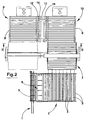
- the embodiment illustrated in figure 4 features a configuration for unloading tiles from the roller stillage 8 and removing them to the production or other lines.
- the embodiment has the advantage of saving the space needed for the storage station in proximity of the loading/unloading end of the kiln.
- the loading/unloading roller plane 20 directly faces the previously-described fixed roller plane 2.
- the transport line supplying or receiving the tiles from the storage apparatus is substituted by the loading/unloading roller provided on the kiln.
- the operation of the rest of the apparatus is the same as in the first embodiment.
- This embodiment has the advantage of saving the space occupied by the connection lines usually place between the loading/unloading roller pane and the storage station.
- this further embodiment also obviates the need for a compensating storage system to come into use when the stillages are being changed.
- This embodiment allows for considerable simplification of the storage station structure.
- FIG 5 there is a configuration for loading and unloading (the equipment can be used equally for either) the tiles from a plurality of roller stillages (in the example, two) onto a production line 20 constituted by a roller stillage for firing ceramic tiles.
- the stations 9 and 10, in which the stillages 8 are positioned are aligned to the production line 20 in such a way that the mobile roller plane 7, in order to transfer the layers of tiles 5 from the fixed roller plane 2 to the roller stillages 8 (or vice versa) has to translate in a parallel direction to the axis of the production line 20 in three positions: a first position in which it is facing the fixed roller plane and the other two positions in which it faces the stillage 8 roller planes positioned in the stations 9 and 10 situated side-by-side, which two stations are arranged on the same longitudinal axis as the production line 20.
- a transmission device is predisposed at each of the stations 9 and 10 which on command drives the rollers of the single roller planes in the stillages 8; these single roller planes are constituted by a horizontal elongate frame 11 which is made to translate in a vertical direction and which is provided with a series of organs 12 for imparting motion to the rollers.
- the illustrated embodiment has a transversal mass which is even further reduced with respect to the previously-described embodiment, and has the same advantage of not requiring the use of any temporary storage for use when a stillage 8 is being changed.
- tile unloading operation In the further embodiment illustrated in figure 6, a very advantageous configuration for the tile unloading operation is shown, where tiles can be unloaded from more than one stillage 8 and sent on to the production line (kiln), and vice versa. In this embodiment too the configuration is completely reversible.
- the peculiarity of this further embodiment consists in the location of the mobile roller plane 7' in front of the production line 20 with its axis coinciding with the longitudinal axis of the production line itself and the stillage 8 arranged in the side-by-side stations 9 and 10.
- the mobile roller plane 7' is positionable in a vertical plane which is parallel to the longitudinal axis of the production line 20.
Abstract
Description
Claims (9)
- An apparatus for loading and unloading tiles (5) from roller stillages, comprising: a fixed roller plane (2), supplied by a conveyor line for formation of layers of tiles, which fixed roller plane (2) is associated to the conveyor line (1) so that rows (6) of tiles (5) formed on the conveyor line can be translated onto the fixed roller plane in a perpendicular direction to the rows formed on the conveyor line; a mobile roller plane for transferring layers of tiles from the fixed roller plane to single roller planes of the stillages and vice versa, the mobile roller plane (7, 7') being couplable with the fixed roller plane (2) in a position which is facing an external side of the fixed roller plane (2); the rollers (3) of the fixed roller plane (2) being perpendicular to the direction along which the rows (6) of tiles (5) formed on the conveyor line (1, 20) are translated and accumulated on the fixed roller plane (2); means being provided for enabling controlled translation of the tiles accumulated on the fixed roller plane (2) onto the mobile roller plane (7) in a perpendicular direction to the direction along which the rows (6) of tiles (5) are accumulated on the conveyor line (1); the mobile roller plane (7) being positionable in a vertical plane arranged parallel or perpendicular to the external side of the fixed roller plane in order to be coupled to roller planes of at least two stillages (8) located in at least two loading or unloading stations (9 and 10) situated side-by-side.
- The apparatus of claim 1, characterised in that a frontal width of the mobile roller (7), perpendicular to the direction of transport, is equal to a corresponding frontal width of the roller planes of the stillages (8) to which the mobile roller (7) is coupled; the external side for loading or unloading of the fixed roller plane (2), parallel to the perpendicular direction along which the rows (6) of tiles formed on the conveyor line are translated and accumulated to form a layer of tiles on the fixed roller plane (2), having at least one tract of length thereof which is equal to the frontal width of the mobile roller plane (7), to which at least one tract of length the mobile roller plane (7) can be coupled.
- The apparatus of claim 1 or 2, characterised in that the means for controlled translation comprise a plurality of conveyor chains (4) positioned between parallel rollers (3) of the fixed roller plane (2), which plurality of conveyor chains (4) can be raised on command from an inactive lower position into an active upper position at which a rest and transport plane is created for the tiles (5) located above the conveyor plane generated by the parallel rollers (3).
- The apparatus of claim 3, characterised in that the loading and unloading stations (9,10) housing the stillages (8) are separated from a device for transmission, on command, of rotation drive to rollers (13) of roller planes of the stillages (8); the device for transmission being commanded to translate in a vertical direction and being provided with two series of organs (12) for moving the rollers (13) which are diametrically opposite and actuated independently of each other to interact with ends of the rollers (13) of the stillages.
- The apparatus of claim 5, characterised in that each of the series of organs (12) for moving the rollers (13) is mounted on a support element (14) which is commanded to move by actuators (15) from an internal rest position to an external working position, at which the series of organs (12) interact with the ends of the rollers (13) of one stillage (8); this action is reversible.
- The apparatus of claim 3, characterised in that a device for transmission is located at each of the stations (9 and 10), which device can be activated on command to transmit rotation to the rollers (13) of the roller planes of the stillages (8); the device being constituted by an elongate horizontal frame (11) which is commanded to translate in a vertical direction and which is provided with a series of organs (12) for moving the rollers (13) of the roller planes of the stillages (8).
- The apparatus of claim 3 or 6, characterised in that the stations (9 and 10) in which the stillages (8) are positioned are aligned with a production line (20); the mobile roller plane (7) for transferring the layers of tiles (5) from the fixed roller planes (2) to the stillages (8), or vice versa, being translatable in a parallel direction to an axis of the production line (20) between three positions: a first position, in which the mobile roller plane (7) faces the fixed roller plane; and two more positions in which the mobile roller plane (7) faces the stillages (8) positioned in the two stations (9 and 10).
- The apparatus of claim 1, characterised in that the frontal width, perpendicular to a direction of transport of the tiles, of the mobile roller plane (7') is equal to a frontal size of the roller planes of the stillage (8), to which it is coupled; the external side of the fixed roller plane (2) is perpendicular to the direction along which the rows (6) of tiles, formed on the line (1) are translated and accumulated to form layers on the fixed roller plane (2), and exhibits at least one tract of length which is equal to the width of the mobile roller plane (7'), to which at least one tract of length the mobile roller plane (7) can be coupled.
- The apparatus of claim 8, characterised in that the means for translating (4) comprise a plurality of conveyor chains (4) positioned between the parallel rollers (3) constituting the mobile roller plane (7'), which can be raised on command from an inactive lower position into an active upper position at which a rest and transport plane is created for the tiles (5) located above the conveyor plane generated by the parallel rollers (3).
Applications Claiming Priority (2)
| Application Number | Priority Date | Filing Date | Title |
|---|---|---|---|
| IT2000MO000222A IT1315683B1 (en) | 2000-10-16 | 2000-10-16 | EQUIPMENT FOR THE LOADING AND UNLOADING OF ARULLI BOX TILES |
| ITMO000222 | 2000-10-16 |
Publications (2)
| Publication Number | Publication Date |
|---|---|
| EP1203737A1 EP1203737A1 (en) | 2002-05-08 |
| EP1203737B1 true EP1203737B1 (en) | 2004-01-02 |
Family
ID=11450588
Family Applications (1)
| Application Number | Title | Priority Date | Filing Date |
|---|---|---|---|
| EP01203866A Expired - Lifetime EP1203737B1 (en) | 2000-10-16 | 2001-10-12 | Apparatus for loading and unloading of tiles from roller stillages |
Country Status (5)
| Country | Link |
|---|---|
| EP (1) | EP1203737B1 (en) |
| AT (1) | ATE257119T1 (en) |
| DE (1) | DE60101661D1 (en) |
| ES (1) | ES2213090T3 (en) |
| IT (1) | IT1315683B1 (en) |
Families Citing this family (7)
| Publication number | Priority date | Publication date | Assignee | Title |
|---|---|---|---|---|
| ITBO20050527A1 (en) * | 2005-08-08 | 2007-02-09 | Sima Srl | EQUIPMENT FOR LOADING UNLOADING OF CERAMIC PRODUCTS FROM ROLLER STORAGE BOX |
| WO2007116419A1 (en) * | 2006-04-11 | 2007-10-18 | Nuova Era S.R.L. | Method and apparatus for loading flat items into multilevel containers |
| DE102007024457B4 (en) * | 2007-05-25 | 2009-04-16 | Hans Lingl Anlagenbau Und Verfahrenstechnik Gmbh & Co. Kg | Loading and unloading station for a dryer rack for moldings, in particular of clay-containing or similar material |
| IT1395183B1 (en) * | 2009-08-06 | 2012-09-05 | Siti B & T Group Spa | LOADING AND UNLOADING PLANT FOR FLAT OR SUBSTANTIALLY FLAT PRODUCTS |
| ITBO20130365A1 (en) * | 2013-07-15 | 2015-01-16 | Nuova Sima Spa | EQUIPMENT FOR LOADING / UNLOADING CERAMIC PRODUCTS IN / FROM ROLLER STORAGE BOXES |
| EP3313760B1 (en) * | 2015-06-23 | 2021-12-15 | Siti - B&T Group S.p.A. | Storage device for ceramic products and the like |
| IT201900020304A1 (en) * | 2019-11-04 | 2021-05-04 | System Ceramics S P A | Handling device for roller boxes |
Family Cites Families (4)
| Publication number | Priority date | Publication date | Assignee | Title |
|---|---|---|---|---|
| ES343499A1 (en) * | 1966-07-30 | 1968-07-16 | Cola | Apparatus for automatic loading and discharge in various structures, floors of clay elements in the production of bricks. (Machine-translation by Google Translate, not legally binding) |
| IT1190308B (en) * | 1986-04-16 | 1988-02-16 | S I T T Soc Impianti Termoelet | APPARATUS FOR LOADING AND UNLOADING CERAMIC MATERIALS ON A ROLLER CONTAINER |
| IT1222157B (en) * | 1987-07-28 | 1990-09-05 | Siti | APPARATUS FOR LOADING AND UNLOADING OF PLATE CERAMIC MATERIALS |
| IT1304918B1 (en) * | 1998-11-02 | 2001-04-05 | Gruppo Barbieri & Tarozzi Srl | MODULAR AUTOMATED LOADING AND UNLOADING STATION FOR CERAMIC AND SIMILAR PRODUCTS. |
-
2000
- 2000-10-16 IT IT2000MO000222A patent/IT1315683B1/en active
-
2001
- 2001-10-12 EP EP01203866A patent/EP1203737B1/en not_active Expired - Lifetime
- 2001-10-12 ES ES01203866T patent/ES2213090T3/en not_active Expired - Lifetime
- 2001-10-12 AT AT01203866T patent/ATE257119T1/en not_active IP Right Cessation
- 2001-10-12 DE DE60101661T patent/DE60101661D1/en not_active Expired - Lifetime
Also Published As
| Publication number | Publication date |
|---|---|
| ITMO20000222A0 (en) | 2000-10-16 |
| DE60101661D1 (en) | 2004-02-05 |
| ES2213090T3 (en) | 2004-08-16 |
| ITMO20000222A1 (en) | 2002-04-16 |
| ATE257119T1 (en) | 2004-01-15 |
| IT1315683B1 (en) | 2003-03-14 |
| EP1203737A1 (en) | 2002-05-08 |
Similar Documents
| Publication | Publication Date | Title |
|---|---|---|
| US4515264A (en) | Assembly line | |
| KR950002514B1 (en) | Web feeding device for corrugator | |
| US5087169A (en) | Palletizing robot | |
| EP1203737B1 (en) | Apparatus for loading and unloading of tiles from roller stillages | |
| ITTO20000124A1 (en) | GROUP FOR THE CLASSIFICATION AND TRANSFER OF GLASS SHEETS. | |
| EP3313760B1 (en) | Storage device for ceramic products and the like | |
| EP0999158B1 (en) | Modular station for the automated loading and unloading of ceramic products and the like | |
| EP1243532B1 (en) | An apparatus for loading and unloading tiles from roller stillages | |
| US4221517A (en) | Brick dehacker and stacker | |
| CN210557755U (en) | Cache line for double-layer S-shaped transportation | |
| US4201506A (en) | Lumber-stacking method and apparatus | |
| JP3568020B2 (en) | Slat conveyor | |
| CN108163251A (en) | Ceramic tile automatic packaging method | |
| SU897528A1 (en) | Unit for producing ceramic tiles | |
| EP1752398B1 (en) | Apparatus for loading/unloading ceramic products to/from roller storage boxes | |
| CN216685979U (en) | Redundant blank stacking equipment | |
| CN214826303U (en) | Stacker that freight efficiency is high | |
| CN214725186U (en) | Brick laying production line with high operation efficiency | |
| CN218659756U (en) | Circulating feeding system for unburned brick production | |
| CN214166194U (en) | Vertical warehouse sorting platform | |
| KR0153868B1 (en) | Apparatus and method of direction to change of the block | |
| KR200356779Y1 (en) | Pallet diverter for various pallet | |
| SU1727999A1 (en) | Line for making laminated wooden material | |
| KR930001881B1 (en) | Bricks loading equipment | |
| CN104986531A (en) | Production line for self-thermal insulation building blocks |
Legal Events
| Date | Code | Title | Description |
|---|---|---|---|
| PUAI | Public reference made under article 153(3) epc to a published international application that has entered the european phase |
Free format text: ORIGINAL CODE: 0009012 |
|
| AK | Designated contracting states |
Kind code of ref document: A1 Designated state(s): AT BE CH CY DE DK ES FI FR GB GR IE IT LI LU MC NL PT SE TR |
|
| AX | Request for extension of the european patent |
Free format text: AL;LT;LV;MK;RO;SI |
|
| 17P | Request for examination filed |
Effective date: 20021016 |
|
| 17Q | First examination report despatched |
Effective date: 20021127 |
|
| AKX | Designation fees paid |
Designated state(s): AT BE CH CY DE DK ES FI FR GB GR IE IT LI LU MC NL PT SE TR |
|
| RAP3 | Party data changed (applicant data changed or rights of an application transferred) |
Owner name: SITITECH SASSUOLO S.R.L. |
|
| GRAH | Despatch of communication of intention to grant a patent |
Free format text: ORIGINAL CODE: EPIDOS IGRA |
|
| GRAS | Grant fee paid |
Free format text: ORIGINAL CODE: EPIDOSNIGR3 |
|
| GRAA | (expected) grant |
Free format text: ORIGINAL CODE: 0009210 |
|
| AK | Designated contracting states |
Kind code of ref document: B1 Designated state(s): AT BE CH CY DE DK ES FI FR GB GR IE IT LI LU MC NL PT SE TR |
|
| PG25 | Lapsed in a contracting state [announced via postgrant information from national office to epo] |
Ref country code: AT Free format text: LAPSE BECAUSE OF FAILURE TO SUBMIT A TRANSLATION OF THE DESCRIPTION OR TO PAY THE FEE WITHIN THE PRESCRIBED TIME-LIMIT Effective date: 20040102 Ref country code: FR Free format text: LAPSE BECAUSE OF FAILURE TO SUBMIT A TRANSLATION OF THE DESCRIPTION OR TO PAY THE FEE WITHIN THE PRESCRIBED TIME-LIMIT Effective date: 20040102 Ref country code: FI Free format text: LAPSE BECAUSE OF FAILURE TO SUBMIT A TRANSLATION OF THE DESCRIPTION OR TO PAY THE FEE WITHIN THE PRESCRIBED TIME-LIMIT Effective date: 20040102 Ref country code: CY Free format text: LAPSE BECAUSE OF FAILURE TO SUBMIT A TRANSLATION OF THE DESCRIPTION OR TO PAY THE FEE WITHIN THE PRESCRIBED TIME-LIMIT Effective date: 20040102 Ref country code: CH Free format text: LAPSE BECAUSE OF FAILURE TO SUBMIT A TRANSLATION OF THE DESCRIPTION OR TO PAY THE FEE WITHIN THE PRESCRIBED TIME-LIMIT Effective date: 20040102 Ref country code: BE Free format text: LAPSE BECAUSE OF FAILURE TO SUBMIT A TRANSLATION OF THE DESCRIPTION OR TO PAY THE FEE WITHIN THE PRESCRIBED TIME-LIMIT Effective date: 20040102 Ref country code: IT Free format text: LAPSE BECAUSE OF FAILURE TO SUBMIT A TRANSLATION OF THE DESCRIPTION OR TO PAY THE FEE WITHIN THE PRESCRIBED TIME-LIMIT;WARNING: LAPSES OF ITALIAN PATENTS WITH EFFECTIVE DATE BEFORE 2007 MAY HAVE OCCURRED AT ANY TIME BEFORE 2007. THE CORRECT EFFECTIVE DATE MAY BE DIFFERENT FROM THE ONE RECORDED. Effective date: 20040102 Ref country code: TR Free format text: LAPSE BECAUSE OF FAILURE TO SUBMIT A TRANSLATION OF THE DESCRIPTION OR TO PAY THE FEE WITHIN THE PRESCRIBED TIME-LIMIT Effective date: 20040102 Ref country code: LI Free format text: LAPSE BECAUSE OF FAILURE TO SUBMIT A TRANSLATION OF THE DESCRIPTION OR TO PAY THE FEE WITHIN THE PRESCRIBED TIME-LIMIT Effective date: 20040102 Ref country code: NL Free format text: LAPSE BECAUSE OF FAILURE TO SUBMIT A TRANSLATION OF THE DESCRIPTION OR TO PAY THE FEE WITHIN THE PRESCRIBED TIME-LIMIT Effective date: 20040102 |
|
| REG | Reference to a national code |
Ref country code: GB Ref legal event code: FG4D |
|
| REG | Reference to a national code |
Ref country code: CH Ref legal event code: EP |
|
| REG | Reference to a national code |
Ref country code: IE Ref legal event code: FG4D |
|
| REF | Corresponds to: |
Ref document number: 60101661 Country of ref document: DE Date of ref document: 20040205 Kind code of ref document: P |
|
| PG25 | Lapsed in a contracting state [announced via postgrant information from national office to epo] |
Ref country code: SE Free format text: LAPSE BECAUSE OF FAILURE TO SUBMIT A TRANSLATION OF THE DESCRIPTION OR TO PAY THE FEE WITHIN THE PRESCRIBED TIME-LIMIT Effective date: 20040402 Ref country code: GR Free format text: LAPSE BECAUSE OF FAILURE TO SUBMIT A TRANSLATION OF THE DESCRIPTION OR TO PAY THE FEE WITHIN THE PRESCRIBED TIME-LIMIT Effective date: 20040402 Ref country code: DK Free format text: LAPSE BECAUSE OF FAILURE TO SUBMIT A TRANSLATION OF THE DESCRIPTION OR TO PAY THE FEE WITHIN THE PRESCRIBED TIME-LIMIT Effective date: 20040402 |
|
| PG25 | Lapsed in a contracting state [announced via postgrant information from national office to epo] |
Ref country code: DE Free format text: LAPSE BECAUSE OF FAILURE TO SUBMIT A TRANSLATION OF THE DESCRIPTION OR TO PAY THE FEE WITHIN THE PRESCRIBED TIME-LIMIT Effective date: 20040403 |
|
| NLV1 | Nl: lapsed or annulled due to failure to fulfill the requirements of art. 29p and 29m of the patents act | ||
| REG | Reference to a national code |
Ref country code: CH Ref legal event code: PL |
|
| REG | Reference to a national code |
Ref country code: ES Ref legal event code: FG2A Ref document number: 2213090 Country of ref document: ES Kind code of ref document: T3 |
|
| PG25 | Lapsed in a contracting state [announced via postgrant information from national office to epo] |
Ref country code: IE Free format text: LAPSE BECAUSE OF NON-PAYMENT OF DUE FEES Effective date: 20041012 Ref country code: LU Free format text: LAPSE BECAUSE OF NON-PAYMENT OF DUE FEES Effective date: 20041012 |
|
| PG25 | Lapsed in a contracting state [announced via postgrant information from national office to epo] |
Ref country code: MC Free format text: LAPSE BECAUSE OF NON-PAYMENT OF DUE FEES Effective date: 20041031 |
|
| PLBE | No opposition filed within time limit |
Free format text: ORIGINAL CODE: 0009261 |
|
| STAA | Information on the status of an ep patent application or granted ep patent |
Free format text: STATUS: NO OPPOSITION FILED WITHIN TIME LIMIT |
|
| 26N | No opposition filed |
Effective date: 20041005 |
|
| EN | Fr: translation not filed | ||
| REG | Reference to a national code |
Ref country code: IE Ref legal event code: MM4A |
|
| PG25 | Lapsed in a contracting state [announced via postgrant information from national office to epo] |
Ref country code: GB Free format text: LAPSE BECAUSE OF NON-PAYMENT OF DUE FEES Effective date: 20051012 |
|
| GBPC | Gb: european patent ceased through non-payment of renewal fee |
Effective date: 20051012 |
|
| REG | Reference to a national code |
Ref country code: ES Ref legal event code: PC2A |
|
| PG25 | Lapsed in a contracting state [announced via postgrant information from national office to epo] |
Ref country code: PT Free format text: LAPSE BECAUSE OF NON-PAYMENT OF DUE FEES Effective date: 20040602 |
|
| PGFP | Annual fee paid to national office [announced via postgrant information from national office to epo] |
Ref country code: ES Payment date: 20191104 Year of fee payment: 19 |
|
| REG | Reference to a national code |
Ref country code: ES Ref legal event code: FD2A Effective date: 20220121 |
|
| PG25 | Lapsed in a contracting state [announced via postgrant information from national office to epo] |
Ref country code: ES Free format text: LAPSE BECAUSE OF NON-PAYMENT OF DUE FEES Effective date: 20201013 |