EP1203677A2 - Suspension assembly - Google Patents
Suspension assembly Download PDFInfo
- Publication number
- EP1203677A2 EP1203677A2 EP01126272A EP01126272A EP1203677A2 EP 1203677 A2 EP1203677 A2 EP 1203677A2 EP 01126272 A EP01126272 A EP 01126272A EP 01126272 A EP01126272 A EP 01126272A EP 1203677 A2 EP1203677 A2 EP 1203677A2
- Authority
- EP
- European Patent Office
- Prior art keywords
- deck
- swing arm
- vehicle
- arm
- air spring
- Prior art date
- Legal status (The legal status is an assumption and is not a legal conclusion. Google has not performed a legal analysis and makes no representation as to the accuracy of the status listed.)
- Withdrawn
Links
- 239000000725 suspension Substances 0.000 title claims abstract description 39
- 230000007935 neutral effect Effects 0.000 claims abstract description 4
- 238000010276 construction Methods 0.000 claims description 2
- 230000008878 coupling Effects 0.000 claims description 2
- 238000010168 coupling process Methods 0.000 claims description 2
- 238000005859 coupling reaction Methods 0.000 claims description 2
- 238000006073 displacement reaction Methods 0.000 description 5
- 230000007246 mechanism Effects 0.000 description 2
- 244000261422 Lysimachia clethroides Species 0.000 description 1
- 230000009471 action Effects 0.000 description 1
- 230000000712 assembly Effects 0.000 description 1
- 238000000429 assembly Methods 0.000 description 1
- 238000006243 chemical reaction Methods 0.000 description 1
- 230000003028 elevating effect Effects 0.000 description 1
- 239000012530 fluid Substances 0.000 description 1
- 239000000446 fuel Substances 0.000 description 1
- 239000002828 fuel tank Substances 0.000 description 1
- 231100001261 hazardous Toxicity 0.000 description 1
- 230000004048 modification Effects 0.000 description 1
- 238000012986 modification Methods 0.000 description 1
Images


Classifications
-
- B—PERFORMING OPERATIONS; TRANSPORTING
- B60—VEHICLES IN GENERAL
- B60P—VEHICLES ADAPTED FOR LOAD TRANSPORTATION OR TO TRANSPORT, TO CARRY, OR TO COMPRISE SPECIAL LOADS OR OBJECTS
- B60P1/00—Vehicles predominantly for transporting loads and modified to facilitate loading, consolidating the load, or unloading
- B60P1/02—Vehicles predominantly for transporting loads and modified to facilitate loading, consolidating the load, or unloading with parallel up-and-down movement of load supporting or containing element
- B60P1/027—Vehicles predominantly for transporting loads and modified to facilitate loading, consolidating the load, or unloading with parallel up-and-down movement of load supporting or containing element with relative displacement of the wheel axles
-
- B—PERFORMING OPERATIONS; TRANSPORTING
- B60—VEHICLES IN GENERAL
- B60G—VEHICLE SUSPENSION ARRANGEMENTS
- B60G11/00—Resilient suspensions characterised by arrangement, location or kind of springs
- B60G11/26—Resilient suspensions characterised by arrangement, location or kind of springs having fluid springs only, e.g. hydropneumatic springs
- B60G11/27—Resilient suspensions characterised by arrangement, location or kind of springs having fluid springs only, e.g. hydropneumatic springs wherein the fluid is a gas
-
- B—PERFORMING OPERATIONS; TRANSPORTING
- B60—VEHICLES IN GENERAL
- B60G—VEHICLE SUSPENSION ARRANGEMENTS
- B60G3/00—Resilient suspensions for a single wheel
- B60G3/02—Resilient suspensions for a single wheel with a single pivoted arm
- B60G3/12—Resilient suspensions for a single wheel with a single pivoted arm the arm being essentially parallel to the longitudinal axis of the vehicle
- B60G3/14—Resilient suspensions for a single wheel with a single pivoted arm the arm being essentially parallel to the longitudinal axis of the vehicle the arm being rigid
-
- B—PERFORMING OPERATIONS; TRANSPORTING
- B60—VEHICLES IN GENERAL
- B60G—VEHICLE SUSPENSION ARRANGEMENTS
- B60G5/00—Resilient suspensions for a set of tandem wheels or axles having interrelated movements
- B60G5/02—Resilient suspensions for a set of tandem wheels or axles having interrelated movements mounted on a single pivoted arm, e.g. the arm being rigid
-
- B—PERFORMING OPERATIONS; TRANSPORTING
- B60—VEHICLES IN GENERAL
- B60P—VEHICLES ADAPTED FOR LOAD TRANSPORTATION OR TO TRANSPORT, TO CARRY, OR TO COMPRISE SPECIAL LOADS OR OBJECTS
- B60P3/00—Vehicles adapted to transport, to carry or to comprise special loads or objects
- B60P3/12—Vehicles adapted to transport, to carry or to comprise special loads or objects for salvaging damaged vehicles
- B60P3/122—Vehicles adapted to transport, to carry or to comprise special loads or objects for salvaging damaged vehicles by supporting the whole vehicle
-
- B—PERFORMING OPERATIONS; TRANSPORTING
- B60—VEHICLES IN GENERAL
- B60G—VEHICLE SUSPENSION ARRANGEMENTS
- B60G2200/00—Indexing codes relating to suspension types
- B60G2200/10—Independent suspensions
- B60G2200/14—Independent suspensions with lateral arms
- B60G2200/141—Independent suspensions with lateral arms with one trailing arm and one lateral arm only
-
- B—PERFORMING OPERATIONS; TRANSPORTING
- B60—VEHICLES IN GENERAL
- B60G—VEHICLE SUSPENSION ARRANGEMENTS
- B60G2202/00—Indexing codes relating to the type of spring, damper or actuator
- B60G2202/10—Type of spring
- B60G2202/15—Fluid spring
- B60G2202/152—Pneumatic spring
-
- B—PERFORMING OPERATIONS; TRANSPORTING
- B60—VEHICLES IN GENERAL
- B60G—VEHICLE SUSPENSION ARRANGEMENTS
- B60G2204/00—Indexing codes related to suspensions per se or to auxiliary parts
- B60G2204/10—Mounting of suspension elements
- B60G2204/14—Mounting of suspension arms
- B60G2204/143—Mounting of suspension arms on the vehicle body or chassis
-
- B—PERFORMING OPERATIONS; TRANSPORTING
- B60—VEHICLES IN GENERAL
- B60G—VEHICLE SUSPENSION ARRANGEMENTS
- B60G2300/00—Indexing codes relating to the type of vehicle
- B60G2300/04—Trailers
-
- B—PERFORMING OPERATIONS; TRANSPORTING
- B60—VEHICLES IN GENERAL
- B60G—VEHICLE SUSPENSION ARRANGEMENTS
- B60G2300/00—Indexing codes relating to the type of vehicle
- B60G2300/38—Low or lowerable bed vehicles
-
- B—PERFORMING OPERATIONS; TRANSPORTING
- B60—VEHICLES IN GENERAL
- B60G—VEHICLE SUSPENSION ARRANGEMENTS
- B60G2500/00—Indexing codes relating to the regulated action or device
- B60G2500/30—Height or ground clearance
Definitions
- This invention relates to a suspension assembly for a vehicle.
- the invention also extends to a suspension assembly and chassis for a vehicle and a vehicle Incorporating these features.
- This invention relates particularly but not exclusively to a suspension assembly for a low loading truck, e.g., which permits lowering of a load platform towards the ground for loading/unloading purposes. The load platform is then raised to the appropriate level during normal ride and travel of the vehicle. It will be convenient to hereinafter describe the invention with reference to this example application, however it is to be clearly understood that it is capable of broader application.
- Trucks typically have a chassis mounted on four or more wheels.
- An operator's cabin is mounted on the chassis towards the front of the vehicle and a load platform is mounted on the rear of the chassis.
- a fuel driven engine e.g., a diesel engine, drives steerable front wheels to move the vehicle.
- a lowerable suspension system for a vehicle deck comprising;
- the swing arm and the links can be cranked.
- cranks of the links can be opposed.
- the medial portion of the swing arm provides a seat for a lower end of the air spring.
- First and second ends of the swing arm can be inclined with respect to one another at an angle between 145 and 155 degrees.
- the first and second links of the shackle arms can be substantially arcuate.
- the tower which provides a contact mounting surface for the top surface of the air spring is inclined at between 5 to 12 degrees from the plane of the deck.
- a lowerable suspension system aforesaid and coupling means for attachment to a driver vehicle said attachment means including a pivotal connection between the driver vehicle, and means for locking and releasing the pivotal connection.
- a chassis and suspension assembly and a vehicle in accordance with this invention may manifest itself in a variety of forms. It will be convenient to hereinafter describe in detail several preferred embodiments of the invention with reference to the accompanying drawings. The purpose of providing this detailed description is to provide an enabling disclosure. It is to be clearly understood however that the specific nature of this description does not supersede the generality of the preceding broad description in the drawings:
- the truck 10 illustrated in Figure 1 is configured as a low loading truck according to the present invention.
- the truck has steerable driven front wheels 11 and a load platform 12 supported by rear chassis rails 13. These rails 13 provide trunnion mountings 14 for respective trailing suspension arms 15 pivotally suspended from the trunnion mountings 14.
- the arms 15 support wheel mountings 16 at their outer ends on which the rear wheels 17 are supported.
- the load platform 12 extends rearwardly from the operators cabin 20 of a conventional four wheel drive vehicle such as a truck or utility, both of which are referred to as a truck herein, in which the chassis 19 rearwardly of the cabin 20 along with the rear wheel drive has been removed.
- the removed portion of the chassis 19 is replaced by the loading platform 12 such that only the operators cabin including the front suspension 21 supporting the steerable front wheels 11 and the engine remains in another possible arrangement (not shown) the cabin can be at the rear of the loading platform.
- the new chassis rails 13 are interconnected at their front ends to a cross-member 22 which mounts pivotally at 25 to a corresponding cross-member 26 fixed to the rear ends of the cut-away chassis rails 19.
- a hydraulic ram 27 controls the pivotal movement between the cross-members 22 and 26 and a further ram 28 controls the operation of locking pins 29 which extend laterally through apertures 30, in brackets mounted on the respective cross-members 22 and 26, when the vehicle 10 is in its normal travelling attitude.
- the load platform is supported by a pair of wheels at each side of the platform 12. However it could be supported by a single wheel at each side if desired or multiple wheels.
- the opposed chassis rails 13 are interconnected by transverse members 34 which extend across the load platform 12 adjacent the location of the trunnion mountings 14 from the suspension arms 15. The transverse members 34 provide lateral stiffness to the trunnion mountings.
- the arms 15 lie closely adjacent the outside face of the respective chassis rails 13 and support the wheels 17 with minimum clearance from the arm 15 so that the overall width of the load platform adjacent the wheels may be maximised while keeping the overall width across the rear wheels within legal limits.
- Each trailing arm 15 independently pivotable about its trunnion mounting 14 and may pivot from a normal sprung or raised driving position, as shown in Figure 1 to a retracted or lowered position, as shown in Figure 2, at which the load platform 12 is lowered between the wheels 17 towards the ground.
- each trailing arm 15 is supported by an air spring assembly 35 supported at its upper end by a tower 36 fixed to the chassis rail 13 and on a platform 38 on the arm 15 at its lower end in front of the wheel 17.
- the air spring 35 is inflated to elevate the load platform 14 to its operative position and provides a resilient support during the elevated travelling position.
- the air spring 35 is supplied with air from a storage tank 40 having sufficient storage capacity to provide quick inflation of all air springs and elevation of the load platform 14 from an on ground position to a travelling position.
- a mechanical or hydraulic receprocable device may be employed.
- An air compressor 41 is mounted in the engine bay of the operators cabin 20 for recharging the tank 40 as is the hydraulic pump for the rams 27 and 28.
- a further two stage hydraulic ram may be connected between the tower 36 and the platform 38 to provide additional lift for quickly elevating the load platform and for providing a back-up support for the load platform.
- hydraulic rams or air mechanical or other hydraulic systems may be adopted.
- Controls for the air supply to the air bags 35 and for the hydraulic fluid supply for the rams are located in the operators cabin 20 and if desired duplicate controls may be provided for operation externally of the cabin 20.
- a fuel tank 45 and the air storage tank 40 are mounted in the space immediately at the front of the load platform 12.
- the load platform 12 may be lowered to an inclined loading position by retraction of the rear suspension means 15.
- the load platform 12 may be lowered to a horizontal on-ground loading position by retraction of the rear suspension means 15 and operation of the hydraulic rams 27 and 28 to pivot the load platform relative to the operators cabin 20.
- the embodiment 50 illustrated in Figure 9 has a fixed connection 51 between the load platform 52 and the operators cabin 53.
- the rear chassis rails 54 are stepped downwardly from the original chassis rails 56 of the operators cabin 57 so that the retraction of the suspension means 58 will pivot the load platform 52 about the front wheels and place the platform 52 close to the ground.
- This embodiment may be more suited to a relative short wheel base vehicle such as a utility.
- the air springs 60 of this embodiment are two part single or double action air springs having a relatively short displacement low stiffness suspension portion 63 and a relatively large displacement high stiffness portion 64.
- Each pneumatic spring assembly 60 is connected between the respective trailing arm 61 and an upper mounting 65 supported by the chassis rails 54, such that when the large displacement portion is deflated, the platform 52 is retracted to move downwardly into engagement with the ground or into close proximity therewith.
- the large displacement high stiffness pneumatic spring 64 is inflated so that the platform 52 is elevated to a travelling position in which conventional springing will be provided by the small displacement low stiffness portion63.
- Separate pneumatic controls are provided in the drivers cabin for the pneumatic spring assemblies so that both the stiffness of the ride and the height adjustment position may be selectively and independently varied to suit the operating conditions. Variations in air pressures will vary the ride and height
- chassis rails, trunnion mountings, trailing arms and suspension units are provided as standard components, such that a variety of four wheel drive vehicles may be readily modified using standard off the shelf components which may be duplicated or used in multiples to accommodate the applied loads expected.
- these components are selected to support the load platform of a four wheel drive utility and thus must be used in multiples for larger vehicles. This will facilitate cost effective conversion of four wheel drive utilities or trucks to front wheel drive low loading vehicles.
- the hydraulic rams 27 are not fully retracted in their normal travelling position such that they may be further retracted to elevate the front end of the substitute load platform 12. This may be accompanied by a further elevation of the back of the load platform by the rear suspension to make it parallel to the ground but at a greater height than the normal travelling position so that a high ground clearance position may be provided.
- a lowerable suspension system for a vehicle comprising a swing arm generally indicated by arrow 70 mounting a road wheel 71 having a first end 72 connected to a chassis rail 73 on the side of a vehicle deck 74, a tower generally indicated by arrow 75 connected to the vehicle deck 74 adjacent a central position of the swing arm 70, and a shackle arm generally indicated by arrow 76 pivotably connected to a second end 77 of the swing arm 70 and the deck 74.
- the shackle arm 76 comprises two links 78, 79 joined by a neutral pivot connection 80 which are pivotably connected to the chassis pail 73 and the second end 77 of the swing arm.
- An air spring 81 is Interposed between the tower 75 and a central portion 82 of the swing arm 70.
- the deck 74 In a first position with the air spring fully inflated the deck 74 is horizontally disposed for normal road travel and in a second position with the air spring deflated the deck is in a lowered position enabling ramp loading and unloading to and from the deck to take place.
- Both the swing arm 70 and the links 78, 79 are cranked, and the cranks of the links 78, 79 are opposed.
- the central portion 82 of the swing arm 70 provides a seat for the lower end of the air spring 81.
- crank in the swing arm 70 is created by an inclination 'P' (See Figure 16) between sections 83 and 84 of between 145 and 155 degrees.
- cranks in each of the links 78 and 79 are substantially arcuate.
- the contact mounting surface of the tower 75 is inclined at an angle of between 5 and 12 degrees with respect to the plane of the deck 74.
- Figures 10 to 14 are illustrative of the suspension system supporting the deck 74 in a horizontal position for travel and Figures 15 and 16 show the suspension system supporting the deck 74 on an incline when the wheel 71 is above the plane of the deck 74.
- the air spring In the travel position the air spring is inflated and in the ramp loading position the air spring is deflated.
- the suspension system Illustrated can be used in pairs for a two wheeled vehicle or in multiple pairs for a vehicle with multiple wheel sets.
- the suspension assembly described above provides a simple yet efficacious mechanism for facilitating lowering of the load tray and associated chassis to the road surface to permit loading/unloading of loads. There are no complex components involved and no moving parts. Further the mechanism can be easily operated by a truck driver.
Landscapes
- Engineering & Computer Science (AREA)
- Mechanical Engineering (AREA)
- Transportation (AREA)
- Health & Medical Sciences (AREA)
- Public Health (AREA)
- Vehicle Body Suspensions (AREA)
Abstract
Description
- This invention relates to a suspension assembly for a vehicle.
- The invention also extends to a suspension assembly and chassis for a vehicle and a vehicle Incorporating these features.
- This invention relates particularly but not exclusively to a suspension assembly for a low loading truck, e.g., which permits lowering of a load platform towards the ground for loading/unloading purposes. The load platform is then raised to the appropriate level during normal ride and travel of the vehicle. It will be convenient to hereinafter describe the invention with reference to this example application, however it is to be clearly understood that it is capable of broader application.
- Trucks typically have a chassis mounted on four or more wheels. An operator's cabin is mounted on the chassis towards the front of the vehicle and a load platform is mounted on the rear of the chassis. Typically a fuel driven engine, e.g., a diesel engine, drives steerable front wheels to move the vehicle.
- Typically forklifts and other lifting devices are used for lifting loads on to the elevated load platform/tray of these trucks. This requires a large amount of work as the load platform is generally positioned a substantial height above the support surface. Further the lifting and lowering operation is a fairly hazardous operation particularly for heavy articles.
- Some attempts have been made to modify trucks to ease or facilitate the loading operation. For example some trucks have tilt down tail portion which can be used to load articles on to the support surface. Articles to be loaded are pushed up or down the inclined tail portion to load the goods on to the load platform. The tail portion is then raised for normal travel and use of the truck.
- Other attempts to address this problem of which the applicant is aware provide part of the load platform as an elevator such that articles may be loaded on to the elevator adjacent ground level and subsequently elevated by the elevator to the level of the load platform. The articles may then be transferred horizontally to any desired part of the load platform. Whilst such arrangements do provide some means for raising the load to load platform they do not provide a loading tray which may be readily disposed adjacent ground level to facilitate loading or unloading which is preferred.
- Clearly it would be advantageous if a contrivance could be provided which enabled the load platform to be lowered for loading/unloading and then raised to its normal height for normal travel of the vehicle.
- According to the present invention there is provided a lowerable suspension system for a vehicle deck comprising;
- (a) a swing arm mounting a road wheel having a first end adapted for pivotal connection to the side of a vehicle deck,
- (b) a tower connected to the vehicle deck adjacent a central position of the swing arm,
- (c) a shackle arm pivotably connected to a second end of the swing arm and the deck, said shackle arm comprising two links joined by a neutral pivotal connection which are pivotably connected to the deck and to the second end of the swing arm,
- (d) an air spring adapted to be Interposed between the tower and the central portion of the swing arm, the arrangement and construction being such that in a first position with the air spring fully inflated the vehicle deck is horizontally disposed for normal travel and in a second position with the air spring deflated the deck is in a lowered position enabling loading and unloading to and from the deck from the ground to take place.
-
- The swing arm and the links can be cranked.
- The cranks of the links can be opposed.
- The medial portion of the swing arm provides a seat for a lower end of the air spring.
- First and second ends of the swing arm can be inclined with respect to one another at an angle between 145 and 155 degrees.
- The first and second links of the shackle arms can be substantially arcuate.
- Wherein the tower which provides a contact mounting surface for the top surface of the air spring is inclined at between 5 to 12 degrees from the plane of the deck.
- According to a further aspect of the present invention there is provided a lowerable suspension system aforesaid and coupling means for attachment to a driver vehicle said attachment means including a pivotal connection between the driver vehicle, and means for locking and releasing the pivotal connection.
- A chassis and suspension assembly and a vehicle in accordance with this invention may manifest itself in a variety of forms. It will be convenient to hereinafter describe in detail several preferred embodiments of the invention with reference to the accompanying drawings. The purpose of providing this detailed description is to provide an enabling disclosure. It is to be clearly understood however that the specific nature of this description does not supersede the generality of the preceding broad description in the drawings:
- Figure 1 is a side view of a typical embodiment of the invention in a normal travelling position;
- Figure 2 is a side view similar to Fig 1 but with the suspension means retracted to a loading attitude;
- Figure 3 is a plan view of the embodiment of the invention illustrated in Fig 1 and shown partially out-away;
- Figures 4 and 5 correspond to Figures 1 and 2 but illustrate the operation of the suspension components;
- Figure 6 is a similar view to Figure 5 but shows the load platform further lowered by pivoting about its connection with the operators cabin;
- Figure 7 illustrates the pivotal connection between existing and new chassis rails;
- Figure 8 is a cut-away perspective view of a suspension and wheel assembly, and
- Figure 9 is a side view of an alternate fixed chassis form of the invention;
- Figure 10 is a top plan view is a suspension assembly and part of a chassis in accordance with another embodiment of the invention in a sprung raised position;
- Figure 11 is a side view of the suspension assembly of Figure 10, and
- Figure 12 is a side view of the suspension assembly of the other (inner side) of the chassis rail, and
- Figures 13 and 14 are enlarged views of the suspension assembly of Figure 10 taken from opposite sides of a chassis side rail with the road wheel removed, and
- Figures 15 and 16 are side views from opposite sides of a chassis side rail with the suspension assembly in a lowered position. In both cases the position of the road wheel is shown in broken outline.
-
- The
truck 10 illustrated in Figure 1 is configured as a low loading truck according to the present invention. The truck has steerable drivenfront wheels 11 and aload platform 12 supported byrear chassis rails 13. Theserails 13 providetrunnion mountings 14 for respective trailingsuspension arms 15 pivotally suspended from thetrunnion mountings 14. Thearms 15 support
wheel mountings 16 at their outer ends on which therear wheels 17 are supported. - The
load platform 12 extends rearwardly from theoperators cabin 20 of a conventional four wheel drive vehicle such as a truck or utility, both of which are referred to as a truck herein, in which thechassis 19 rearwardly of thecabin 20 along with the rear wheel drive has been removed. The removed portion of thechassis 19 is replaced by theloading platform 12 such that only the operators cabin including thefront suspension 21 supporting the steerablefront wheels 11 and the engine remains in another possible arrangement (not shown) the cabin can be at the rear of the loading platform. - The
new chassis rails 13 are interconnected at their front ends to across-member 22 which mounts pivotally at 25 to acorresponding cross-member 26 fixed to the rear ends of the cut-away chassis rails 19. Ahydraulic ram 27 controls the pivotal movement between thecross-members further ram 28 controls the operation oflocking pins 29 which extend laterally throughapertures 30, in brackets mounted on therespective cross-members vehicle 10 is in its normal travelling attitude. - In this embodiment the load platform is supported by a pair of wheels at each side of the
platform 12. However it could be supported by a single wheel at each side if desired or multiple wheels. As illustrated theopposed chassis rails 13 are interconnected bytransverse members 34 which extend across theload platform 12 adjacent the location of thetrunnion mountings 14 from thesuspension arms 15. Thetransverse members 34 provide lateral stiffness to the trunnion mountings. - It will be seen that the
arms 15 lie closely adjacent the outside face of therespective chassis rails 13 and support thewheels 17 with minimum clearance from thearm 15 so that the overall width of the load platform adjacent the wheels may be maximised while keeping the overall width across the rear wheels within legal limits. - Each
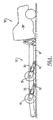
trailing arm 15 independently pivotable about its trunnion mounting 14 and may pivot from a normal sprung or raised driving position, as shown in Figure 1 to a retracted or lowered position, as shown in Figure 2, at which theload platform 12 is lowered between thewheels 17 towards the ground. - Referring to Figure 8 it will be seen that each trailing
arm 15 is supported by anair spring assembly 35 supported at its upper end by atower 36 fixed to thechassis rail 13 and on aplatform 38 on thearm 15 at its lower end in front of thewheel 17. Theair spring 35 is inflated to elevate theload platform 14 to its operative position and provides a resilient support during the elevated travelling position. Theair spring 35 is supplied with air from astorage tank 40 having sufficient storage capacity to provide quick inflation of all air springs and elevation of theload platform 14 from an on ground position to a travelling position. As an alternative to the air spring 35 a mechanical or hydraulic receprocable device may be employed. - An air compressor 41 is mounted in the engine bay of the
operators cabin 20 for recharging thetank 40 as is the hydraulic pump for therams tower 36 and theplatform 38 to provide additional lift for quickly elevating the load platform and for providing a back-up support for the load platform. As an alternative to hydraulic rams or air, mechanical or other hydraulic systems may be adopted. - Controls for the air supply to the
air bags 35 and for the hydraulic fluid supply for the rams are located in theoperators cabin 20 and if desired duplicate controls may be provided for operation externally of thecabin 20. Afuel tank 45 and theair storage tank 40 are mounted in the space immediately at the front of theload platform 12. - As illustrated in Figures 2 and 6, the
load platform 12 may be lowered to an inclined loading position by retraction of the rear suspension means 15. Theload platform 12 may be lowered to a horizontal on-ground loading position by retraction of the rear suspension means 15 and operation of thehydraulic rams operators cabin 20. - The
embodiment 50 illustrated in Figure 9 has a fixedconnection 51 between theload platform 52 and theoperators cabin 53. However in this embodiment the rear chassis rails 54 are stepped downwardly from the original chassis rails 56 of the operators cabin 57 so that the retraction of the suspension means 58 will pivot theload platform 52 about the front wheels and place theplatform 52 close to the ground. This embodiment may be more suited to a relative short wheel base vehicle such as a utility. - The air springs 60 of this embodiment are two part single or double action air springs having a relatively short displacement low
stiffness suspension portion 63 and a relatively large displacementhigh stiffness portion 64. Eachpneumatic spring assembly 60 is connected between the respective trailingarm 61 and an upper mounting 65 supported by the chassis rails 54, such that when the large displacement portion is deflated, theplatform 52 is retracted to move downwardly into engagement with the ground or into close proximity therewith. - For travelling purposes, the large displacement high stiffness
pneumatic spring 64 is inflated so that theplatform 52 is elevated to a travelling position in which conventional springing will be provided by the small displacement low stiffness portion63. Separate pneumatic controls are provided in the drivers cabin for the pneumatic spring assemblies so that both the stiffness of the ride and the height adjustment position may be selectively and independently varied to suit the operating conditions. Variations in air pressures will vary the ride and height - From the above it will be seen that a conventional four wheel drive truck or utility may be readily converted to a low loading configuration as per the above described embodiments. Suitably the chassis rails, trunnion mountings, trailing arms and suspension units are provided as standard components, such that a variety of four wheel drive vehicles may be readily modified using standard off the shelf components which may be duplicated or used in multiples to accommodate the applied loads expected. For this purpose these components are selected to support the load platform of a four wheel drive utility and thus must be used in multiples for larger vehicles. This will facilitate cost effective conversion of four wheel drive utilities or trucks to front wheel drive low loading vehicles.
- In the embodiment illustrated in Figures 1 to 8, the
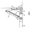
hydraulic rams 27 are not fully retracted in their normal travelling position such that they may be further retracted to elevate the front end of thesubstitute load platform 12. This may be accompanied by a further elevation of the back of the load platform by the rear suspension to make it parallel to the ground but at a greater height than the normal travelling position so that a high ground clearance position may be provided. - With respect to Figures 10 to 16 of the drawings in a further embodiment of the present invention there Is provided a lowerable suspension system for a vehicle comprising a swing arm generally indicated by
arrow 70 mounting aroad wheel 71 having afirst end 72 connected to achassis rail 73 on the side of avehicle deck 74, a tower generally indicated byarrow 75 connected to thevehicle deck 74 adjacent a central position of theswing arm 70, and a shackle arm generally indicated byarrow 76 pivotably connected to asecond end 77 of theswing arm 70 and thedeck 74. - The
shackle arm 76 comprises twolinks neutral pivot connection 80 which are pivotably connected to thechassis pail 73 and thesecond end 77 of the swing arm. - An
air spring 81 is Interposed between thetower 75 and acentral portion 82 of theswing arm 70. - In a first position with the air spring fully inflated the
deck 74 is horizontally disposed for normal road travel and in a second position with the air spring deflated the deck is in a lowered position enabling ramp loading and unloading to and from the deck to take place. - Both the
swing arm 70 and thelinks links - The
central portion 82 of theswing arm 70 provides a seat for the lower end of theair spring 81. - The crank in the
swing arm 70 is created by an inclination 'P' (See Figure 16) betweensections - The cranks in each of the
links - The contact mounting surface of the
tower 75 is inclined at an angle of between 5 and 12 degrees with respect to the plane of thedeck 74. - In the drawings Figures 10 to 14 are illustrative of the suspension system supporting the
deck 74 in a horizontal position for travel and Figures 15 and 16 show the suspension system supporting thedeck 74 on an incline when thewheel 71 is above the plane of thedeck 74. - In the travel position the air spring is inflated and in the ramp loading position the air spring is deflated.
- In the travel position the
links - The suspension system Illustrated can be used in pairs for a two wheeled vehicle or in multiple pairs for a vehicle with multiple wheel sets.
- The suspension system described in relation to Figures 10-15 has many disadvantages in relation to the earlier known embodiments, the main advantages being;
- (a) The system allows a deck to be lowered completely to the ground because the assembly is mounted to the outside of chassis rails of the deck,
- (b) In the lowered position the swing arm assembly is not an encumbrance to lowering of the deck to ground level,
- (c) The shackle connection is bunched when the deck is in its traveling position and provides lateral support relative to the deck and the free end of the swing arm during travelling,
- (d) The crank in the spring arm enables optimum operating position to be obtained for the air springs between the deflated and inflated conditions.
-
- The suspension assembly described above provides a simple yet efficacious mechanism for facilitating lowering of the load tray and associated chassis to the road surface to permit loading/unloading of loads. There are no complex components involved and no moving parts. Further the mechanism can be easily operated by a truck driver.
- It will of course be realised that the above has been given only by way of illustrative example of the Invention and that all such modifications and variations thereto as would be apparent to persons skilled in the art are deemed to fall within the broad scope and ambit of the invention as is defined in the appended claims.
Claims (8)
- A lowerable suspension system for a vehicle deck comprising;(a) a swing arm mounting a road wheel having a first end adapted for pivotal connection to the side of a vehicle deck,(b) a tower connected to the vehicle deck adjacent a central position of the swing arm,(c) a shackle arm pivotably connected to a second end of the swing arm and the deck, said shackle arm comprising two links joined by a neutral pivotal connection which are pivotably connected to the deck and to the second end of the swing arm,(d) an air spring adapted to be interposed between the tower and the central portion of the swing arm, the arrangement and construction being such that in a first position with the air spring fully inflated the vehicle deck is horizontally disposed for normal travel and in a second position with the air spring deflated the deck is in a lowered position enabling loading and unloading to and from the deck from the ground to take place.
- A lowerable suspension system as claimed in claim 1 wherein the swing arm and the links are cranked.
- A lowerable suspension arm as claimed in claim 2 wherein the cranks of the links are opposed.
- A lowerable suspension system as claimed in of claims 1 wherein the medial portion of the swing arm provides a seat for a lower end of the air spring.
- A suspension system as claimed in any one of claim 1 wherein first and second ends of the swing arm are inclined with respect to one another at an angle between 145 and 155 degrees.
- A suspension arm as claimed in claim 2 wherein the first and second links of the shackle arms are substantially arcuate.
- A suspension arm as claimed in of claim 1 wherein the tower provides a contact mounting surface for the top surface of the air spring is inclined at between 5 to 12 degrees from the plane of the deck.
- A vehicle comprising a chassis and deck, a lowerable suspension system as claimed in claim 1 and coupling means for attachment to a driver vehicle said attachment means including a pivotal connection between the driver vehicle, and means for locking and releasing the pivotal connection.
Applications Claiming Priority (3)
| Application Number | Priority Date | Filing Date | Title |
|---|---|---|---|
| US702282 | 1996-08-23 | ||
| US707282 | 2000-11-06 | ||
| US09/707,282 US6530580B1 (en) | 1999-05-12 | 2000-11-06 | Suspension assembly related application |
Publications (2)
| Publication Number | Publication Date |
|---|---|
| EP1203677A2 true EP1203677A2 (en) | 2002-05-08 |
| EP1203677A3 EP1203677A3 (en) | 2004-02-11 |
Family
ID=24841087
Family Applications (1)
| Application Number | Title | Priority Date | Filing Date |
|---|---|---|---|
| EP01126272A Withdrawn EP1203677A3 (en) | 2000-11-06 | 2001-11-06 | Suspension assembly |
Country Status (3)
| Country | Link |
|---|---|
| US (1) | US6530580B1 (en) |
| EP (1) | EP1203677A3 (en) |
| AU (1) | AU782034B2 (en) |
Cited By (2)
| Publication number | Priority date | Publication date | Assignee | Title |
|---|---|---|---|---|
| WO2006106347A1 (en) * | 2005-04-08 | 2006-10-12 | Juan Carlos Moliner Casani | Improvements in and relating to suspension assemblies |
| NL2006643C2 (en) * | 2011-04-20 | 2012-10-23 | Veldhuizen B V | Semi-trailer equipped with tiltable loading floor with airbeams. |
Families Citing this family (14)
| Publication number | Priority date | Publication date | Assignee | Title |
|---|---|---|---|---|
| US20050242532A1 (en) * | 2004-01-06 | 2005-11-03 | Deo Hrishikesh V | Suspension system with independent control of ride-height, stiffness and damping |
| US20050184485A1 (en) * | 2004-02-13 | 2005-08-25 | Joseph Timmermans | Folding trailer with kneeling device |
| DK200400445A (en) * | 2004-03-19 | 2005-09-20 | Falck Schmidt S Maskinfabrik A | Self-propelled vehicle, for support or service of aircraft |
| US20050253352A1 (en) * | 2004-05-14 | 2005-11-17 | Ziech James F | Semi-trailing arm high cube rear suspension |
| CA2498403A1 (en) * | 2005-02-22 | 2006-08-22 | Emil Rudiger | Suspension system for a vehicle |
| US7950675B1 (en) * | 2005-05-13 | 2011-05-31 | Absolute Electronic Solutions, Inc. | Cargo carrier |
| GB2453338A (en) * | 2007-10-02 | 2009-04-08 | Portaramp Ltd | A vehicle transporter unit |
| NZ596627A (en) * | 2008-01-04 | 2013-03-28 | Innovare Motion Pty Ltd | A Trailer With Lowerable and Raisable Trailer Bed with a pneumatic atuating means actuable on the force carrying structure to raise or lower the trailer frame |
| US7976029B2 (en) * | 2009-04-29 | 2011-07-12 | Richard T. Plummer | Airplane trailer |
| AU2009100804B4 (en) * | 2009-08-14 | 2010-06-17 | Thanh Son Nguyen | Adjustable height trailer |
| US8740241B2 (en) * | 2009-12-07 | 2014-06-03 | Concaten, Inc. | Mobile barrier |
| US9296273B2 (en) * | 2013-10-14 | 2016-03-29 | Agco Corporation | Machine suspension and height adjustment |
| US9688113B2 (en) * | 2015-07-14 | 2017-06-27 | Cnh Industrial America Llc | System for adjusting frame height of an agricultural vehicle |
| CN113942571A (en) * | 2021-11-30 | 2022-01-18 | 重庆凯斯瑞机电设备有限公司 | High-strength two-bridge swing arm |
Citations (1)
| Publication number | Priority date | Publication date | Assignee | Title |
|---|---|---|---|---|
| US5855378A (en) | 1995-08-23 | 1999-01-05 | Capehart; Jeffrey L. | Elevator suspension and method of use |
Family Cites Families (18)
| Publication number | Priority date | Publication date | Assignee | Title |
|---|---|---|---|---|
| US2957594A (en) | 1959-06-11 | 1960-10-25 | Roderick L Brenneman | Lift truck |
| US3044646A (en) * | 1959-08-17 | 1962-07-17 | Henry L Sperow | Trailer for boats |
| US3113686A (en) * | 1960-12-19 | 1963-12-10 | Clifford K Brown | Boat trailer |
| US3214185A (en) | 1962-03-05 | 1965-10-26 | Int Harvester Co | Control means for a motor vehicle suspension system of the pneumatic type |
| FR2252232A1 (en) | 1973-11-23 | 1975-06-20 | Sage Jacques | Vehicle transporter lorry with winch - has lowerable chassis on jack controlled links connected to wheels |
| US4132432A (en) | 1976-10-01 | 1979-01-02 | Raidel John E | Air ride suspension assemblies |
| US4619578A (en) | 1985-04-19 | 1986-10-28 | Routledge James H | Retractable wheel suspension apparatus |
| JPH0811484B2 (en) | 1985-09-27 | 1996-02-07 | 日産自動車株式会社 | Vehicle suspension control device |
| US4693486A (en) | 1986-04-09 | 1987-09-15 | Lear Siegler, Inc. | Trailing arm suspension with wrapper compression axle mounting |
| US4934733A (en) | 1989-02-22 | 1990-06-19 | Dbx Corporation | Trailer suspension apparatus |
| US4966387A (en) | 1989-05-31 | 1990-10-30 | White Iv Thomas E | Supplemental suspension system and method for supplementing the suspension system of a vehicle |
| EP0413318A1 (en) * | 1989-08-15 | 1991-02-20 | Paccar Inc. | Axle suspension system |
| DE9000124U1 (en) | 1990-01-08 | 1990-03-15 | Dusar, Heinz, 5450 Neuwied | Shower partition |
| JPH07501505A (en) | 1991-12-09 | 1995-02-16 | ナウエル,コーベット ウェルドン | Flexible suspension system |
| AU666572B2 (en) | 1992-10-19 | 1996-02-15 | Hendrickson International Corporation | Axle suspension systems |
| DE4332266C2 (en) | 1993-09-23 | 1995-07-13 | Daimler Benz Ag | Freight wagons to form a rail-bound freight train for combined rail / road freight transport |
| US5482155A (en) | 1994-09-12 | 1996-01-09 | Foster; Raymond K. | Reciprocating floor conveyor and floor member |
| US5887880A (en) * | 1996-05-22 | 1999-03-30 | Anadarko Bank & Trust Company | Squatdown axle and suspension system |
-
2000
- 2000-11-06 US US09/707,282 patent/US6530580B1/en not_active Expired - Lifetime
-
2001
- 2001-11-06 AU AU89226/01A patent/AU782034B2/en not_active Ceased
- 2001-11-06 EP EP01126272A patent/EP1203677A3/en not_active Withdrawn
Patent Citations (1)
| Publication number | Priority date | Publication date | Assignee | Title |
|---|---|---|---|---|
| US5855378A (en) | 1995-08-23 | 1999-01-05 | Capehart; Jeffrey L. | Elevator suspension and method of use |
Cited By (2)
| Publication number | Priority date | Publication date | Assignee | Title |
|---|---|---|---|---|
| WO2006106347A1 (en) * | 2005-04-08 | 2006-10-12 | Juan Carlos Moliner Casani | Improvements in and relating to suspension assemblies |
| NL2006643C2 (en) * | 2011-04-20 | 2012-10-23 | Veldhuizen B V | Semi-trailer equipped with tiltable loading floor with airbeams. |
Also Published As
| Publication number | Publication date |
|---|---|
| AU8922601A (en) | 2002-05-09 |
| AU782034B2 (en) | 2005-06-30 |
| US6530580B1 (en) | 2003-03-11 |
| EP1203677A3 (en) | 2004-02-11 |
Similar Documents
| Publication | Publication Date | Title |
|---|---|---|
| US6530580B1 (en) | Suspension assembly related application | |
| US6231294B1 (en) | Independent wheel-lift having a chassis mounted pivot point | |
| US5951235A (en) | Advanced rollback wheel-lift | |
| US7950675B1 (en) | Cargo carrier | |
| US11358508B2 (en) | Lift systems and methods for supporting cargo on a vehicle | |
| US6338470B1 (en) | Powered lift for raising a two-wheeled vehicle | |
| EP1829815B1 (en) | A forklift truck | |
| EP0545996A1 (en) | Suspension system and body for large dump trucks | |
| US4382632A (en) | Dumping vehicle stabilizer system | |
| US20110268543A1 (en) | Container trailer | |
| US4375903A (en) | Vehicle suspension system augmenter | |
| US20060119061A1 (en) | Suspension system for dump truck/paver truck hitch | |
| US6561589B2 (en) | Dual acting truck hoist | |
| CA2044127C (en) | Dumping semi-trailer | |
| CN219133967U (en) | Slide rail type full landing plate obstacle removing vehicle | |
| RU215214U1 (en) | TRAILER | |
| JP4598670B2 (en) | Truck with inclined deck | |
| EP0049121A2 (en) | Improved mechanical handling apparatus | |
| US7384231B2 (en) | Bogie unit for suspended transport of a treatment plant | |
| GB2169576A (en) | A wheeled barrow | |
| JP2017030389A (en) | Vehicle transportation truck | |
| JP2002274244A (en) | Low-floor type trailer | |
| JP2595631Y2 (en) | Dump structure of a dump truck with lifting platform | |
| JP2509522Y2 (en) | Car-only car | |
| IE950175A1 (en) | A lifting mechanism |
Legal Events
| Date | Code | Title | Description |
|---|---|---|---|
| PUAI | Public reference made under article 153(3) epc to a published international application that has entered the european phase |
Free format text: ORIGINAL CODE: 0009012 |
|
| 17P | Request for examination filed |
Effective date: 20011106 |
|
| AK | Designated contracting states |
Kind code of ref document: A2 Designated state(s): AT BE CH CY DE DK ES FI FR GB GR IE IT LI LU MC NL PT SE TR |
|
| AX | Request for extension of the european patent |
Free format text: AL;LT;LV;MK;RO;SI |
|
| PUAL | Search report despatched |
Free format text: ORIGINAL CODE: 0009013 |
|
| AK | Designated contracting states |
Kind code of ref document: A3 Designated state(s): AT BE CH CY DE DK ES FI FR GB GR IE IT LI LU MC NL PT SE TR |
|
| AX | Request for extension of the european patent |
Extension state: AL LT LV MK RO SI |
|
| RIC1 | Information provided on ipc code assigned before grant |
Ipc: 7B 60G 7/00 B Ipc: 7B 60P 3/12 B Ipc: 7B 60G 11/27 B Ipc: 7B 60G 3/14 B Ipc: 7B 60G 5/02 A |
|
| AKX | Designation fees paid |
Designated state(s): AT BE CH CY DE DK ES FI FR GB GR IE IT LI LU MC NL PT SE TR |
|
| RAP1 | Party data changed (applicant data changed or rights of an application transferred) |
Owner name: LO-TOW AXLES PTY LTD |
|
| RIN1 | Information on inventor provided before grant (corrected) |
Inventor name: SIMPSON, JOHN EDWARD |
|
| 17Q | First examination report despatched |
Effective date: 20070724 |
|
| GRAP | Despatch of communication of intention to grant a patent |
Free format text: ORIGINAL CODE: EPIDOSNIGR1 |
|
| STAA | Information on the status of an ep patent application or granted ep patent |
Free format text: STATUS: THE APPLICATION IS DEEMED TO BE WITHDRAWN |
|
| 18D | Application deemed to be withdrawn |
Effective date: 20101027 |