EP1203232B1 - Chromatographievorrichtung mit direkter heizung der kapillarkolonne - Google Patents
Chromatographievorrichtung mit direkter heizung der kapillarkolonne Download PDFInfo
- Publication number
- EP1203232B1 EP1203232B1 EP00989001A EP00989001A EP1203232B1 EP 1203232 B1 EP1203232 B1 EP 1203232B1 EP 00989001 A EP00989001 A EP 00989001A EP 00989001 A EP00989001 A EP 00989001A EP 1203232 B1 EP1203232 B1 EP 1203232B1
- Authority
- EP
- European Patent Office
- Prior art keywords
- temperature
- column
- conductive element
- covering sheath
- type
- Prior art date
- Legal status (The legal status is an assumption and is not a legal conclusion. Google has not performed a legal analysis and makes no representation as to the accuracy of the status listed.)
- Expired - Lifetime
Links
Images

Classifications
-
- G—PHYSICS
- G05—CONTROLLING; REGULATING
- G05D—SYSTEMS FOR CONTROLLING OR REGULATING NON-ELECTRIC VARIABLES
- G05D23/00—Control of temperature
- G05D23/19—Control of temperature characterised by the use of electric means
- G05D23/1906—Control of temperature characterised by the use of electric means using an analogue comparing device
- G05D23/1912—Control of temperature characterised by the use of electric means using an analogue comparing device whose output amplitude can take more than two discrete values
-
- G—PHYSICS
- G01—MEASURING; TESTING
- G01N—INVESTIGATING OR ANALYSING MATERIALS BY DETERMINING THEIR CHEMICAL OR PHYSICAL PROPERTIES
- G01N30/00—Investigating or analysing materials by separation into components using adsorption, absorption or similar phenomena or using ion-exchange, e.g. chromatography or field flow fractionation
- G01N30/02—Column chromatography
- G01N30/26—Conditioning of the fluid carrier; Flow patterns
- G01N30/28—Control of physical parameters of the fluid carrier
- G01N30/30—Control of physical parameters of the fluid carrier of temperature
- G01N2030/3053—Control of physical parameters of the fluid carrier of temperature using resistive heating
- G01N2030/3061—Control of physical parameters of the fluid carrier of temperature using resistive heating column or associated structural member used as heater
Definitions
- the present invention relates to apparatus for chromatography in which the capillary column is heated directly and to a method of controlling the temperature of the capillary column.
- the Overton patent suggests to use a filament made of conductive material inserted into the sheath or the conductive tube in close contact with the column but insulated electrically from the other conductive element (tube or filament) used to heat the column.
- a control device able to determine the temperature of the conductor as a function of its resistance is employed to regulate the heating of the column.
- the control device cyclically compares the set temperature with that calculated on the basis of the temperature sensor signal and corrects the power supplied to the heating conductor by varying the voltage applied to the same.
- the possibility of using the same heating conductor as temperature sensor is also suggested, without however specifying what kind of control device could be suitable for this particular embodiment.
- a system for heating the column by means of a tube conductor which contains the same column is illustrated in US-A-5,808,178 and in the corresponding international patent application n. WO 97/14957 in the name of Thermedics.
- the temperature control system alternates cycles of supplying constant high voltage to heat the tube conductor, with measurement cycles of more limited constant voltage to measure the resistance of the tube conductor and, consequently, the temperature of the tube/column system.
- standard PI or PID type standard industrial controllers is suggested as an improvement of a similar system.
- the object of the present invention is to propose a chromatography apparatus with direct heating of the column that gives particularly precise control of the temperature of the column.
- Another object of the present invention is to propose a chromatography apparatus with direct heating of the column that can guarantee high response speed, maintaining in any case the necessary precision with respect to the set temperature profiles, be they linear or not linear (e.g. exponential and polynomial)
- a chromatography apparatus of the type comprising at least one capillary column and means to control the temperature of the column, comprising at least one element made of electrically conductive material to heat directly the capillary column, and means for controlling the temperature of the capillary column comprising a control device operating according to a mathematical model having one component of predictive type, or of Feed Forward type, which describes the thermodynamic behavior of the assembly comprising the electrically conducting element and the column at least as a function of the thermal resistance and the thermal capacity of the cited assembly to regulate the supply of electrical energy to the conductive element.
- the behavior of the conductive element is therefore simulated by one model component that takes account of the thermodynamic characteristics of the conductor/column assembly to determine what power must be applied to the conductive element to obtain the pre-established temperature at a given time. That in particular allows a fast response to unexpected variations of the temperature profiles set up for the analysis.
- the model comprises also one component preferably of corrective or Feed Back type, to correct any errors of temperature that may be introduced by the predictive component of the model.
- the system of the present invention operates according to a mathematical model that describes the thermodynamic behavior of the system under the form of a transfer function determined by two very well-defined algorithms.
- the powers determined on the basis of the two model components can also be "weighted" as a function of the requirement that needs to be privileged in any determined application
- the temperature control device is able to cyclically update the parameters of the mathematical model and, in particular, at least the values of thermal capacity and thermal resistance.
- the same element in electrically conductive material destined for the heating of the column.
- the column and the conductive element are disposed in one covering sheath, in conditions of close mutual contact for all the length contained inside the same sheath. This allows effective thermal exchange to be maintained between conductive element and column for all their length and to limit thermal losses.
- the covering sheath is preferably made of electrically insulating material and the column/conductor/sheath assembly can be wrapped in coils without undesired short circuits occurring that might prejudice the correct operation of the system.
- the element in electrically conductive material is made in the form of a filament.
- the system and the method for controlling the temperature according to the invention are applicable to any type of directly heated column assembly in which it is present a conductive element made according to a different form.
- control system adopted in the apparatus according to the present invention can also be used in the case in which a further conductive element is used, separate from the heating element, to detect the temperature of the column.
- the covering sheath is made from electrically insulating material and is preferably able to resist high temperatures, such as ceramic fibers or similar, for example.
- the sheath can also be made from a thermo-shrinking type of material.
- the materials currently known having such characteristic can not support high temperatures much above 200 °C, but this does allow the filament and the column to be easily introduced into the inside of the sheath before the assembly thus formed is subjected to heating to allow the contraction of the sheath and to obtain the desired close contact between column and filament.
- the invention further relates to a method for controlling the temperature of a capillary column in a chromatography apparatus, wherein at least one element made of electrically conductive material to heat directly the capillary column is used, and the control of the temperature is carried out according to a mathematical model having a component of the predictive type, or Feed Forward type, which describes the thermodynamic behavior of the assembly comprising the electrically conductive element and the column at least as a function of the thermal resistance and the thermal capacity of said assembly to regulate the supply of electrical power to the conductive element.
- a mathematical model having a component of the predictive type, or Feed Forward type, which describes the thermodynamic behavior of the assembly comprising the electrically conductive element and the column at least as a function of the thermal resistance and the thermal capacity of said assembly to regulate the supply of electrical power to the conductive element.
- the temperature control system illustrated in Figure 1 comprises a functional block 10 able to memorize and update the relative parameters of the thermodynamic model of the assembly constituted by a conductive element 100, made for example in the form of a filament, and by a capillary column 200 ( Figures from 3 to 5).
- the conductive filament 100 made for example from metal such as nickel or other conductive material, is placed in close contact with the capillary column 200, made of fused silica for example, inside a sheath 300.
- filament 100 is also used as temperature sensor.
- the covering sheath 300 is produced in electrically insulating material, such as, for example, ceramic fibers.
- electrically insulating material such as, for example, ceramic fibers.
- materials can also be employed with characteristics compatible with particular requirements, such as a thermo-shrinking material (e.g. TeflonTM), or polyamide or the like.
- a thermo-shrinking type material could facilitate the fabrication of the assembly constituted by filament 100, column 200 and sheath 300, even if currently the greater part of the known thermo-shrinking materials are not particularly resistant to high temperatures.
- an electrically insulating material for the sheath allows the assembly comprising the filament, the column and the same sheath to be wrapped in coils without any contact occurring between various parts of the same filament, contact that would unavoidably prejudice the operation of the system.
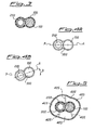
- the chosen configuration for filament 100 and column 200 inserted into sheath 300 allows the different expansions between filament 100 and column 200 to be compensated in function of the temperature even in the case in which the sheath/filament/column assembly is wrapped in coils.
- Figure 4A shows the assembly at room temperature starting from a hypothetical condition of alignment of the straight line A that joins the centers of column 200 and filament 100 with respect to a horizontal plane P on which lies the straight line A corresponding to a given section, plane P on which also lies substantially one coil of the sheath/filament/column assembly in wrapped condition.
- the greater thermal expansion of filament 100 transforms into a deformation of the assembly shown in Figure 4B .
- filament 100 rotates with respect to column 200 causing the straight line A that connects the two centers to be inclined at an angle ⁇ with respect to plane P as a function of the difference of linear expansion to which filament and column in each coil are subject.
- the assembly is therefore equipped with an elastic geometry in which the different linear expansions of the conductive element 100 and column 200 are transformed into deformations that involve only slight variations of the mutual position of the conductive element and the column inside the sheath.
- functional block 10 receives cyclically the information DT set and T set relative to the desired temperature profile, information coming from a data processing unit or data input device, for example, or from a dedicated controller already present in the chromatography apparatus (not shown).
- DT set represents the desired temperature variation, i.e. the desired heating speed
- T set represents the instantaneous value of the set up temperature.
- Information on the ambient temperature T amb also reaches functional block 10 supplied by a suitable sensor 15.
- the separate supply of values DT set and T set allows advantageously even temperature profiles with non-linear features, for example profiles of temperature with exponential or polynomial features, to be set up and followed with particular precision.
- the output 11 of the functional block 10 drives a power unit 20 able to supply to the heating element, such as filament 100 in conductive material, the voltage (and therefore the power) necessary to constantly follow the set up temperature profile with particular precision.
- T c can for example be calculated on the basis of values of T c estimated and memorized in a table, using interpolation techniques for intermediate values.
- the values of coefficient ⁇ for each temperature can be memorized in a table or the variations ⁇ as a function of the temperature with respect to the value ⁇ considered constant.
- T c thus determined from second calculation block 50 is cyclically compared in 60 with the value of the set-point temperature T set in such way as to determine the temperature error Err T between the set-point temperature and that effectively obtained at a given step.
- the value corresponding to the temperature error Err T is taken as input to a block 70 that has the function of " observer ", together to DT set value of the derivative of the temperature profile to be followed.
- the observer block 70 determines the new values of thermal resistance R th and thermal capacity C th that must be sent as input to functional block 10 in order to update the parameters of the mathematical model that describes the thermodynamic behavior of filament 100 and to permit correct control of the power unit 20.
- All the cyclical operations are repeated at high frequency, for example with a period less than a millisecond, so as to obtain high precision of reproduction of the desired temperature profile.
- control system allows - even at operational speed - temperature profiles with particularly high heating speeds to be followed easily (for example heating speed up to approximately 25 °C/s) while maintaining a good precision.
- the initial parameters of the mathematical model it is possible for example to determine the resistance of filament 100 at a first pre-established temperature and therefore to establish the variation of the resistance of the filament when the same is taken to a second pre-established temperature, different from the previous one, according to a pre-established way, for example by applying a step variation to the power supplied to the heating element.
- This allows the initial values of thermal resistance and thermal capacity of the model to be found, as well as the length of the column to be calculated if the cross-section of filament 100 is known or, if this is not known, for example, the effective length of column 200 to be determined, or to verify that the length of column 200 associated with heating filament 100 is effectively that pre-established.
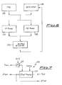
- Figure 6 shows a functional diagram of a model that can be applied to every iteration of the system.
- the blocks shown in this diagram taken as a whole, control the power supplied to the system, in the form of a supply voltage V sup , and therefore control the temperature of the column.
- the model comprises for example a DATA INPUT block, indicated by reference 500, that acquires a number of input variables at step n-1 and a TPG (Temperatures Profiles Generator) block, indicated by reference 510, which generates the desired temperature profiles, i.e. not only linear profiles of temperature (isotherms and ramps) but also exponential or polynomial profiles.
- a DATA INPUT block indicated by reference 500
- a TPG Tempotures Profiles Generator
- V sup (n) represents the supply voltage that must be supplied to the system in its entirety, not only to supply power to the column and thus obtain the T set (n) , temperature, i.e. the desired set-point temperature at step n , but also to supply the control circuit.
- Block 510 In Figure 7 the scheme of block 510 that generates the desired temperature profiles is shown in more detail.
- block 510 generates the correct sequence of set points that describe a desired temperature profile.
- T set (n) is the desired temperature at step n
- T set (n-1) is the temperature detected at the previous step n-1
- DT set is the rate of change of the temperature
- t samp is the sampling period.
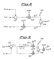
- Figure 8 shows the predictive component 530 of the model or FF model.
- This model component is used to predict the power which needs to be supplied to the system to obtain a given temperature T set when the system is subject to a heating speed of DT set .
- the two components - static power Ps (in constant temperature condition) and dynamic power P D (in variable temperature condition whether linear or non-linear) - to be supplied at step n are calculated taking account of the thermal resistance R th and the thermal capacity C th of the system, as well as the ambient temperature T amb in which the system operates.
- a subtraction operator 531 calculates the difference between the set temperature T set and the ambient temperature T amb , while a multiplication operator 532 multiplies the difference thus calculated by factor G th to give static power P S FF .
- C th and R th are recalculated at every iteration of the model to follow the change of physical characteristics of the system which vary with the varying temperature.
- the model of Figure 8 therefore provides for a multiplication operator 533 that multiplies factor DT set and factor C th to give dynamic power P D FF calculated according to the Feed Forward model.
- a sum operator 534 is therefore provided that calculates power P FF as output.
- Figure 9 shows the corrective component 550 of the model or FB model.
- the Feed Back component of the model supplies a corrective effect on the power calculated in Feed Forward taking account of the static, temperature error Err T and of its first derivative DErr T with respect to time.
- the subtraction operator 551 shown in Figure 9 calculates this difference.
- GD FB has dimensions °C/sec
- Figure 10 shows voltage actuator 570 of the supply voltage V sup that allows to calculate the supply voltage to be applied to the entire system as a function of the power calculated on the basis of the predictive model (P FF ) and the corrective model (P FB ), so that the column reaches the desired set-point temperature of T set (n) at step n .
- R sup the internal resistance of the control system.
- the value of R s depends on the same control circuit and can also be affected for example by the construction of the power/measurement terminals applied to the heating element of the column.
- powers can also be "weighted " before being added, in such a way as to privilege one or more characteristics with respect to others, for example the speed of response with respect to the precision, or vice versa.
- a logical operator 572 could be provided (even though it is not absolutely necessary) in series with the sum operator 571 predisposed to sum the factors (weighed or not) in relation (14). This latter makes it possible (if necessary) to maintain nonetheless a minimal power P min whenever the calculated power P set is less than the same minimal power.
- V set P set * R c 1 ⁇ 2 in which R c is the resistance of the column, or rather of its heating element, measured at the previous step (n-1).
- the multiplication operator 573 and the square root extraction operator 574 implement this relation.
- R S n V sup n - 1 - V c n - 1 / l c n - 1
- the cyclical updating of the values of thermal resistance R th and thermal capacity C th of the column can be accomplished at every step in various ways.
- the power P set supplied to the column heating element in a certain step can be considered as the sum of the static power Ps and the dynamic power P D .
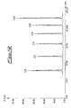
- Figure 12 shows a chromatogram of a test analysis carried out on a mixture containing C 10 -C 20 in C 6 , employing H 2 as carrier.
- the test was carried out using a capillary column 1.2 m in length, with internal diameter of 0.25 ⁇ m and external diameter of 0.1 mm.
- the gas chromatography apparatus was equipped with a split type injector with pressure of 114 kPa, flow of 1 cc/min at a temperature of 250 °C; the output detector was of FID type maintained at a temperature of 300 °C.
- the temperature profile was set up for 0,1 min to 80 °C and was increased until a temperature of 250 °C with a variation speed of 10 °C/sec.
- Table 1 shows the result of the tests done on 20 analyses of samples with the same C 10 -C 20 composition to estimate the repeatability of the peak areas.
- Table 1 Compound Mean Peak Area ( ⁇ Volt * sec) Relative Standard Deviation (%) C 10 41840.5 1.44 C 12 33701.8 1.71 C 14 36509.6 1.53 C 16 36838.4 1.59 C 18 37024.6 1.99 C 20 54709.7 2.1
- Table 2 shows the result of the tests done on 20 analyses of samples with the same C 10 -C 20 composition to estimate the repeatability of the retention times of the peaks.
- Table 2 Compound Retention times (sec.) Relative Standard Deviation (%) C 10 8.21 0.43 C 12 12.31 0.32 C 14 15.94 0.21 C 16 18.88 0.17 C 18 21.29 0.17 C 20 23.34 0.13
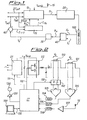
- FIG. 2 shows a circuit diagram of a temperature control system according to the present invention.
- the system comprises in particular a main power section 21 that receives electrical power from a source, for example the mains, and is able to distribute the voltage V sup necessary to the operation of the system, among which in particular the voltage necessary to supply section 22 which supplies electrical power to heating element 100 of column 200.
- the analogue value of voltage V c applied to heating element 100 is determined at the terminals of the same, while the analogue value of current I c that circulates in heating element 100 is determined by a measurement resistor 101 (or shunt) in the form of the voltage V l at its terminals.
- the value of V C measured at the terminals of heating element 100 is preferably standardized with respect to the length of the same element corresponding to section 102. This standardized value is amplified in 103 before being converted to digital form by an A/D converter 104 and being sent as input to a micro-controller or a DSP (Digital Signal Processor) indicated with reference 17.
- the information on the length of heating filament 100 can easily be calculated in the starting phase of the system and memorized in micro-controller or DSP 17, which then sends it to block 102 through link 110.
- the analogue value of I c shown in the form of the voltage V l across resistor 101, is amplified in 105 before being converted to digital form by an A/D converter 106 and being sent as input to micro-controller or DSP 17.
- Micro-controller or DSP 17 moreover also receives the value of the ambient temperature from sensor 15 under the form of a converted analogue signal that is first amplified in 107 and then converted into digital form by an A/D converted 108.
- Micro-controller or DSP 17 comprises two output lines 111 and 112 that go respectively to control the main supply section 21, that commands the variation of the supply voltage V sup to the system, and supply section 22 which is designed to supply the correct voltage to heating element 100.
- Micro-controller or DSP 17 can moreover communicate through the bi-directional line 115 with an external unit 150 for processing or inputting data.
- a possible embodiment of the present invention provides for micro-controller or DSP 17 moreover to control the electric motor of an impeller 130 through a suitable driver circuit. 120.
- an electro-valve can be set in action that controls the flow of a cooling gas.
- the assembly constituted by filament 100, column 200 and the covering sheath 300 is preferably lodged in a slack way inside a tubular container 400 to allow the air moved by impeller 130, or the cooling gas supplied through an appropriate electro-valve, to circulate in the space 403 comprised between the inner wall of the tubular covering 400 and the external wall of the covering sheath 300.
- Spacers 405 (shown by broken line in Figure 5 ) can be associated to container 400 with substantially radial alignment to avoid interruptions of the airflow driven by impeller 130. According to this aspect of the present invention, it is possible to accelerate the cooling of column 200.
Landscapes
- Physics & Mathematics (AREA)
- General Physics & Mathematics (AREA)
- Engineering & Computer Science (AREA)
- Automation & Control Theory (AREA)
- Health & Medical Sciences (AREA)
- Life Sciences & Earth Sciences (AREA)
- Chemical & Material Sciences (AREA)
- Analytical Chemistry (AREA)
- Biochemistry (AREA)
- General Health & Medical Sciences (AREA)
- Immunology (AREA)
- Pathology (AREA)
- Control Of Temperature (AREA)
- Treatment Of Liquids With Adsorbents In General (AREA)
- Other Investigation Or Analysis Of Materials By Electrical Means (AREA)
- Finger-Pressure Massage (AREA)
- Air-Conditioning For Vehicles (AREA)
- Thermotherapy And Cooling Therapy Devices (AREA)
- Photoreceptors In Electrophotography (AREA)
- Crystals, And After-Treatments Of Crystals (AREA)
- Pharmaceuticals Containing Other Organic And Inorganic Compounds (AREA)
- Feedback Control In General (AREA)
Claims (30)
- Chromatographievorrichtung desjenigen Typs, der zumindest eine Kapillarsäule (200) und Mittel zur Steuerung der Temperatur dieser Säule enthält, umfassend zumindest ein aus einem elektrisch leitenden Material gefertigten Element (100), um die zumindest eine Kapillarsäule (200) direkt zu erwärmen und wobei die Mittel zur Steuerung der Temperatur dieser Kapillarsäule (200) eine Steuereinrichtung aufweist, die gemäß einem mathematischen Modell arbeitet, dadurch gekennzeichnet, dass das mathematische Modell eine Komponente (530) entsprechend des voraussagenden Typs oder des Typs der Mittkopplung aufweist, das das thermodynamische Verhalten der Baugruppe umfassend das elektrisch leitende Element (100) und die Säule (200) zumindest als Funktion des Wärmeleitwiderstandes und der Wärmkapazität dieser Baugruppe beschreibt, um die Versorgung des elektrischen Leiters mit elektrischer Spannung (Vsup) zu regulieren.
- Eine Vorrichtung nach Anspruch 1, wobei das mathematische Model weiterhin eine Komponente des Typs mit Korrekturwirkung (550) oder Rückkopplung umfasst.
- Eine Vorrichtung nach Anspruch 1 oder 2, wobei die Einrichtung geeignet ist zur regelmäßigen Aktualisierung der Parameter des mathematischen Modells.
- Eine Vorrichtung nach Anspruch 1, wobei die Mittel zur Steuerung der Temperatur der Säule (200) zumindest eine Einrichtung umfasst, die geeignet ist, um die den Anschlüssen des leitenden Elements zugeführte Spannung (Vsup) und die Stromstärke des Stroms, der in dem leitenden Element (100) fließt, regelmäßig zu bestimmen.
- Eine Vorrichtung nach Anspruch 1, wobei die Mittel zur Steuerung der Temperatur der Kappilarsäule (200) zumindest eine Einrichtung umfasst, die geeignet ist, um den elektrischen Wärmeleitwiderstand des elektrisch leitenden Elementes (100) als eine Funktion der Spannung, die den Anschlüssen des elektrisch leitenden Elements (100) zugeführt wird und der Stromstärke des Stroms, der in dem leitenden Element (100) fließt, regelmäßig zu bestimmen.
- Eine Vorrichtung nach Anspruch 1, wobei die Mittel zur Steuerung der Temperatur der Kappilarsäule (200) zumindest eine Einrichtung umfasst, die geeignet ist, um die Temperatur der Säule (200) als eine Funktion der Spannung, die den Anschlüssen des elektrisch leitenden Elements (100) zugeführt wird und der Stromstärke des Stroms, der in dem leitenden Element (100) fließt, regelmäßig zu bestimmen.
- Eine Vorrichtung nach Anspruch 1, gekennzeichnet weiterhin durch das Vorhandensein von Mitteln zur Erfassung der Temperatur der Säule (200).
- Eine Vorrichtung nach Anspruch 7, wobei die Mittel zur Erfassung der Temperatur der Säule (200) das Element aus einem elektrisch leitenden Material umfasst, und wobei die zumindest eine Säule (200) und das zumindest eine elektrisch leitende Element (100) innerhalb einer Umhüllung (300) in einem engen gegenseitigen Kontakt über die ganze Länge innerhalb dieser Umhüllung vorgesehen sind.
- Eine Vorrichtung nach Anspruch 1, wobei das Element aus einem elektrisch leitenden Material (100) in Form eines Filamentes hergestellt ist.
- Eine Vorrichtung nach Anspruch 8, wobei die Umhüllung (300) aus einem elektrisch isolierenden Material gefertigt ist.
- Eine Vorrichtung nach Anspruch 8, wobei die Umhüllung (300) aus keramischen Fasern gefertigt ist.
- Eine Vorrichtung nach Anspruch 8, wobei die Umhüllung (300) aus einem Material gefertigt ist, das bei Wärmeeinwirkung schrumpft.
- Eine Vorrichtung nach Anspruch 8, gekennzeichnet durch das Vorhandensein eines röhrenförmigen Behälters (400) innerhalb dem die Baugruppe bestehend aus der Kapillarsäule (200), dem Filament aus einem leitenden Material (100) und der Umhüllung (300) lose angeordnet ist.
- Eine Vorrichtung nach Anspruch 13, wobei Mittel bereitgestellt sind zur Beförderung und Zirkulation eines Fluids für den Wärmeaustausch innerhalb des Raumes, der zwischen der inneren Wand des röhrenförmigen Behälters (400) und der äußeren Wand der Umhüllung (300) angeordnet ist.
- Ein Verfahren zur Steuerung der Temperatur einer Kapillarsäule (200) in einer Chromatographievorrichtung unter Verwendung von zumindest einem aus einem elektrisch leitenden Material gefertigten Element (100), um die Kapillarsäule (200) direkt zu erwärmen und wobei die Steuerung der Temperatur gemäß einem mathematischen Modell durchgeführt wird, dadurch gekennzeichnet, dass das mathematische Modell eine Komponente (530) entsprechend des voraussagenden Typs oder des Typs der Mittkopplung aufweist, das das thermodynamische Verhalten der Baugruppe umfassend das elektrisch leitende Element (100) und die Säule zumindest als Funktion des Wärmeleitwiderstandes und der Wärmkapazität dieser Baugruppe beschreibt, um die Versorgung des elektrischen Leiters mit elektrischer Spannung zu regulieren.
- Ein Verfahren nach Anspruch 15, wobei das mathematische Model weiterhin eine Komponente des Typs mit Korrekturwirkung (550) oder Rückkopplung umfasst.
- Ein Verfahren Anspruch 15 oder 16, wobei die Parameter des mathematischen Modells regelmäßig aktualisiert werden.
- Ein Verfahren Anspruch 15, wobei die Kapillarsäule (200) und das leitende Element (100) innerhalb einer Umhüllung (300) in einem engen gegenseitigen Kontakt angeordnet sind.
- Ein Verfahren Anspruch 15, gekennzeichnet durch die Erfassung der Temperatur der Säule (200).
- Ein Verfahren Anspruch 19, wobei die Temperatur der Säule (200) mit Hilfe des Elementes aus einem elektrisch leitenden Material erfasst wird.
- Ein Verfahren Anspruch 15, wobei das Element aus einem elektrisch leitenden Material (100) in Form eines Filamentes hergestellt ist.
- Ein Verfahren Anspruch 18, wobei die Umhüllung (300) aus einem elektrisch isolierenden Material gefertigt ist.
- Ein Verfahren Anspruch 22, wobei die Umhüllung (300) aus keramischen Fasern gefertigt ist.
- Ein Verfahren Anspruch 22, wobei die Umhüllung (300) aus einem Material gefertigt ist, das bei Wärmeeinwirkung schrumpft.
- Ein Verfahren Anspruch 15, wobei die Baugruppe bestehend aus der Kapillarsäule (200), dem Filament aus einem leitenden Material (100) und der Umhüllung (300) innerhalb eines röhrenförmigen Behälters (400) lose angeordnet ist.
- Ein Verfahren Anspruch 25, wobei die Zirkulation eines Fluids für den Wärmeaustausch in dem Raum vorgesehen ist, der zwischen der inneren Wand des röhrenförmigen Behälters (400) und der äußeren Wand der Umhüllung (300) angeordnet ist.
- Ein Verfahren Anspruch 17, wobei die Parameter des Models regelmäßig berechnet und aktualisiert werden, auf Basis der Information des Temperaturprofils, das innerhalb einer bestimmten Zeitspanne erreicht werden soll, wobei die Information mindestens den momentanen Temperaturwert und mindestens den momentanen Wert seiner Abweichung bezüglich der Zeit umfasst.
- Ein Verfahren nach Anspruch 15, gekennzeichnet durch regelmäßige Erfassung der den Anschlüssen des leitenden Elements (100) zugeführten Spannung und der Stromstärke des Stroms, der in dem leitenden Element (100) fließt.
- Ein Verfahren nach Anspruch 15, gekennzeichnet durch regelmäßige Bestimmung des elektrischen Wärmeleitwiderstandes des elektrisch leitenden Elementes (100) als eine Funktion der Spannung, die den Anschlüssen des elektrisch leitenden Elements (100) zugeführt wird und der Stromstärke des Stroms, der in dem leitenden Element (100) fließt.
- Ein Verfahren nach Anspruch 15, gekennzeichnet durch regelmäßige Bestimmung der Temperatur innerhalb der Umhüllung als eine Funktion der Spannung, die den Anschlüssen des elektrisch leitenden Elements (100) zugeführt wird und der Stromstärke des Stroms, der in dem leitenden Element (100) fließt.
Applications Claiming Priority (3)
| Application Number | Priority Date | Filing Date | Title |
|---|---|---|---|
| ITMI992708 | 1999-12-27 | ||
| IT1999MI002708A IT1313967B1 (it) | 1999-12-27 | 1999-12-27 | Sistema e metodo per controllare la temperatura di una colonna percromatografia. |
| PCT/IT2000/000541 WO2001048469A2 (en) | 1999-12-27 | 2000-12-21 | Chromatography apparatus with direct heating of the capillary column |
Publications (2)
| Publication Number | Publication Date |
|---|---|
| EP1203232A2 EP1203232A2 (de) | 2002-05-08 |
| EP1203232B1 true EP1203232B1 (de) | 2009-04-01 |
Family
ID=11384194
Family Applications (1)
| Application Number | Title | Priority Date | Filing Date |
|---|---|---|---|
| EP00989001A Expired - Lifetime EP1203232B1 (de) | 1999-12-27 | 2000-12-21 | Chromatographievorrichtung mit direkter heizung der kapillarkolonne |
Country Status (7)
| Country | Link |
|---|---|
| US (1) | US6579345B2 (de) |
| EP (1) | EP1203232B1 (de) |
| JP (1) | JP2003518621A (de) |
| AT (1) | ATE427484T1 (de) |
| DE (1) | DE60041921D1 (de) |
| IT (1) | IT1313967B1 (de) |
| WO (1) | WO2001048469A2 (de) |
Families Citing this family (21)
| Publication number | Priority date | Publication date | Assignee | Title |
|---|---|---|---|---|
| IT1319652B1 (it) | 2000-11-15 | 2003-10-23 | Thermoquest Italia Spa | Colonna per cromatografia. |
| US7048968B2 (en) * | 2003-08-22 | 2006-05-23 | Micron Technology, Inc. | Methods of depositing materials over substrates, and methods of forming layers over substrates |
| DE112005001907B4 (de) * | 2004-08-07 | 2022-06-15 | Waters Technologies Corp. (N.D.Ges.D. Staates Delaware) | Passive Säulenvorheizung mit Merkmal zur Reduzierung der Probenbandenverbreitung |
| CN102929309A (zh) | 2005-01-25 | 2013-02-13 | 欧西里其有限责任公司 | 用于具有不同热容的少量流体样品的温度控制器 |
| US8642931B2 (en) * | 2006-03-13 | 2014-02-04 | Valco Instruments Company, L.P. | Adaptive temperature controller |
| ITMI20060813A1 (it) * | 2006-04-21 | 2007-10-22 | Thermo Electron Spa | Dispositivo di adsorbimento di co2 per strumenti di analisi elementare. |
| US7735352B2 (en) * | 2006-05-16 | 2010-06-15 | Alliant Techsystems Inc. | Multi-dimensional portable gas chromatograph system |
| US7742880B2 (en) * | 2006-06-20 | 2010-06-22 | Seer Technology, Inc. | Apparatus, system, and method for broad spectrum chemical detection |
| US7806963B2 (en) * | 2006-06-20 | 2010-10-05 | Seer Technology, Inc. | Apparatus, system, and method for improved power utilization in a gas chromatography sensor |
| US20090158820A1 (en) * | 2007-12-20 | 2009-06-25 | Schlumberger Technology Corporation | Method and system for downhole analysis |
| EP2112507A1 (de) * | 2008-04-25 | 2009-10-28 | Varian B.V. | Vorrichtung und Verfahren für direkte Widerstandsheizung von Leitungen |
| WO2010028398A2 (en) | 2008-09-08 | 2010-03-11 | Falcon Analytical Systems & Technology | Fast micro gas chromatograph system |
| DE102008054546B3 (de) * | 2008-12-11 | 2010-06-17 | Gerhard Dr. Krebs | Verbessertes Trennsäulenmodul für einen Gas-Chromatographen |
| EP2341425A1 (de) * | 2009-12-30 | 2011-07-06 | STMicroelectronics (Grenoble 2) SAS | Steuerung von elektrischen Maschinen wobei eine Quadratwurzel berechnet wird |
| US10302605B2 (en) * | 2011-02-07 | 2019-05-28 | Agilent Technologies, Inc. | Column assembly for a gas chromatograph |
| US20130180405A1 (en) * | 2012-01-13 | 2013-07-18 | Ron W. Currie | Gas Chromatography Capillary Devices and Methods |
| CN103018380A (zh) * | 2012-11-27 | 2013-04-03 | 张勇 | 一种电压可调直热式色谱柱 |
| AU2017290706B2 (en) * | 2016-06-28 | 2022-06-23 | Perkinelmer U.S. Llc | Improved low thermal mass GC module |
| US10324069B2 (en) | 2017-02-24 | 2019-06-18 | Valco Instruments Company, L.P. | Chromatographic system temperature control system |
| DE102017110258B3 (de) * | 2017-05-11 | 2018-11-08 | Sim Scientific Instruments Manufacturer Gmbh | Chemisches Analysegerät mit einer Mediumaufbereitungseinheit und Mediumaufbereitungseinheit |
| CN118243825B (zh) * | 2024-05-21 | 2024-08-06 | 精智未来(广州)智能科技有限公司 | 基于微型气相色谱法的有机样品分析方法及系统 |
Family Cites Families (17)
| Publication number | Priority date | Publication date | Assignee | Title |
|---|---|---|---|---|
| US3305000A (en) * | 1965-02-08 | 1967-02-21 | Barber Colman Co | Temperature control system for chromatographs |
| US4726822A (en) * | 1984-10-22 | 1988-02-23 | Honeywell Inc. | Fast response thermochromatographic capillary columns |
| US5028243A (en) * | 1988-12-22 | 1991-07-02 | University Of Dayton | Gas chromatography methods and apparatus |
| US4923486A (en) * | 1988-12-22 | 1990-05-08 | University Of Dayton | Gas chromatography methods and apparatus |
| US5114439A (en) * | 1989-06-27 | 1992-05-19 | University Of Florida | Direct resistive heating and temperature measurement of metal-clad capillary columns in gas chromatography and related separation techniques |
| US5005399A (en) * | 1989-08-16 | 1991-04-09 | Brunswick Corporation | Resistively heated gas chromatograph system |
| US5032151A (en) * | 1990-01-17 | 1991-07-16 | Hewlett-Packard Company | System and method for automated cool on-column injection with column diameters less than 530 μm |
| US5135549A (en) * | 1991-01-30 | 1992-08-04 | The Board Of Trustees Of Southern Illinois University | Chromatographic technique and apparatus |
| US5544276A (en) * | 1993-11-30 | 1996-08-06 | Microsensors Technology, Inc. | Miniature gas chromatograph with heated gas inlet fitting, heated tubing, and heated microvalve assembly |
| US5611846A (en) * | 1994-01-14 | 1997-03-18 | Board Of Supervisors Of Louisiana State University And Agricultural And Mechanical College | Portable gas chromatograph |
| DE4419596C1 (de) * | 1994-06-03 | 1995-06-01 | Gerstel Gmbh | Thermodesorptionseinrichtung für einen Gaschromatographen |
| EP0876607B1 (de) * | 1995-10-16 | 2007-05-09 | Thermo Orion Inc. | Hochgeschwindigkeitschromatographie |
| US5634961A (en) * | 1995-11-07 | 1997-06-03 | Hewlett-Packard Company | Gas chromatography system with thermally agile oven |
| US5596876A (en) * | 1995-11-28 | 1997-01-28 | Scientific Instrument Services, Inc. | Miniaturized cryogenic trap apparatus |
| US6103112A (en) * | 1996-11-13 | 2000-08-15 | Transgenomic, Inc. | MIPC chromatographic apparatus with improved temperature control |
| US5782964A (en) * | 1997-01-27 | 1998-07-21 | Rvm Scientific, Inc. | Gas chromatography column assembly temperature control system |
| US6209386B1 (en) * | 1998-06-05 | 2001-04-03 | Rvm Scientific, Inc. | Electrically insulated gas chromatograph assembly and method of fabricating same |
-
1999
- 1999-12-27 IT IT1999MI002708A patent/IT1313967B1/it active
-
2000
- 2000-12-21 US US09/868,555 patent/US6579345B2/en not_active Expired - Fee Related
- 2000-12-21 AT AT00989001T patent/ATE427484T1/de not_active IP Right Cessation
- 2000-12-21 JP JP2001548933A patent/JP2003518621A/ja active Pending
- 2000-12-21 EP EP00989001A patent/EP1203232B1/de not_active Expired - Lifetime
- 2000-12-21 DE DE60041921T patent/DE60041921D1/de not_active Expired - Lifetime
- 2000-12-21 WO PCT/IT2000/000541 patent/WO2001048469A2/en not_active Ceased
Also Published As
| Publication number | Publication date |
|---|---|
| WO2001048469A3 (en) | 2002-02-21 |
| WO2001048469A2 (en) | 2001-07-05 |
| US20020178912A1 (en) | 2002-12-05 |
| ITMI992708A0 (it) | 1999-12-27 |
| ATE427484T1 (de) | 2009-04-15 |
| IT1313967B1 (it) | 2002-09-26 |
| DE60041921D1 (de) | 2009-05-14 |
| JP2003518621A (ja) | 2003-06-10 |
| ITMI992708A1 (it) | 2001-06-27 |
| US6579345B2 (en) | 2003-06-17 |
| EP1203232A2 (de) | 2002-05-08 |
Similar Documents
| Publication | Publication Date | Title |
|---|---|---|
| EP1203232B1 (de) | Chromatographievorrichtung mit direkter heizung der kapillarkolonne | |
| US10761069B2 (en) | Heated transfer line | |
| EP0855596B1 (de) | Gaschromatographiesystem | |
| US5808178A (en) | High speed gas chromatography | |
| US6666907B1 (en) | Temperature programmable microfabricated gas chromatography column | |
| US6666074B2 (en) | Apparatus for conducting high-temperature liquid chromatography analysis | |
| US4570054A (en) | Open loop control for spectrophotometer atomizer furnace | |
| EP1994537B1 (de) | Adaptiver temperaturregler | |
| CN102265703A (zh) | 自适应温度控制器 | |
| US6530686B1 (en) | Differential scanning calorimeter having low drift and high response characteristics | |
| WO2013134150A1 (en) | System and method for improving the accuracy of a rate of decay measurement for real time correction in a mass flow controller or mass flow meter by using a thermal model to minimize thermally induced error in the rod measurement | |
| JP3775541B2 (ja) | クロマトグラフィーカラム用のキャリブレーション方法 | |
| CN114113383B (zh) | 用于隔热色谱柱的技术 | |
| JP3620981B2 (ja) | 試料温度制御方法 | |
| EP4495728A2 (de) | Gaschromatografiesäulenheizungssteuerung mit mehreren temperatursensoren | |
| JPH0536363U (ja) | ガスクロマトグラフの温度制御装置 | |
| EP2112507A1 (de) | Vorrichtung und Verfahren für direkte Widerstandsheizung von Leitungen | |
| Penzel et al. | Calibration parameter drift compensation of metal resistive bolometers operating in a thermal varying environment | |
| HK1131851B (en) | Adaptive temperature controller | |
| Becsek et al. | THEORETICAL ANALYSIS OF THERMISTOR TRIMMING | |
| WO2021211689A1 (en) | Dynamically adjusting set points for a heating/cooling element of a chromatography column using available information | |
| JPS58186036A (ja) | 温度特性測定装置 | |
| Meacham et al. | Fan-induced heating | |
| JP2000146877A (ja) | 昇温脱離法のための試料加熱方法 |
Legal Events
| Date | Code | Title | Description |
|---|---|---|---|
| PUAI | Public reference made under article 153(3) epc to a published international application that has entered the european phase |
Free format text: ORIGINAL CODE: 0009012 |
|
| 17P | Request for examination filed |
Effective date: 20010802 |
|
| AK | Designated contracting states |
Kind code of ref document: A2 Designated state(s): AT BE CH CY DE DK ES FI FR GB GR IE IT LI LU MC NL PT SE TR |
|
| 17Q | First examination report despatched |
Effective date: 20080609 |
|
| GRAP | Despatch of communication of intention to grant a patent |
Free format text: ORIGINAL CODE: EPIDOSNIGR1 |
|
| RAP1 | Party data changed (applicant data changed or rights of an application transferred) |
Owner name: THERMO ELECTRON S.P.A. |
|
| GRAS | Grant fee paid |
Free format text: ORIGINAL CODE: EPIDOSNIGR3 |
|
| GRAA | (expected) grant |
Free format text: ORIGINAL CODE: 0009210 |
|
| AK | Designated contracting states |
Kind code of ref document: B1 Designated state(s): AT BE CH CY DE DK ES FI FR GB GR IE IT LI LU MC NL PT SE TR |
|
| REG | Reference to a national code |
Ref country code: GB Ref legal event code: FG4D |
|
| REG | Reference to a national code |
Ref country code: CH Ref legal event code: EP |
|
| REG | Reference to a national code |
Ref country code: IE Ref legal event code: FG4D |
|
| REF | Corresponds to: |
Ref document number: 60041921 Country of ref document: DE Date of ref document: 20090514 Kind code of ref document: P |
|
| NLV1 | Nl: lapsed or annulled due to failure to fulfill the requirements of art. 29p and 29m of the patents act | ||
| PG25 | Lapsed in a contracting state [announced via postgrant information from national office to epo] |
Ref country code: ES Free format text: LAPSE BECAUSE OF FAILURE TO SUBMIT A TRANSLATION OF THE DESCRIPTION OR TO PAY THE FEE WITHIN THE PRESCRIBED TIME-LIMIT Effective date: 20090712 Ref country code: PT Free format text: LAPSE BECAUSE OF FAILURE TO SUBMIT A TRANSLATION OF THE DESCRIPTION OR TO PAY THE FEE WITHIN THE PRESCRIBED TIME-LIMIT Effective date: 20090902 Ref country code: AT Free format text: LAPSE BECAUSE OF FAILURE TO SUBMIT A TRANSLATION OF THE DESCRIPTION OR TO PAY THE FEE WITHIN THE PRESCRIBED TIME-LIMIT Effective date: 20090401 Ref country code: FI Free format text: LAPSE BECAUSE OF FAILURE TO SUBMIT A TRANSLATION OF THE DESCRIPTION OR TO PAY THE FEE WITHIN THE PRESCRIBED TIME-LIMIT Effective date: 20090401 |
|
| RAP2 | Party data changed (patent owner data changed or rights of a patent transferred) |
Owner name: THERMO FISHER SCIENTIFIC S.P.A |
|
| PG25 | Lapsed in a contracting state [announced via postgrant information from national office to epo] |
Ref country code: SE Free format text: LAPSE BECAUSE OF FAILURE TO SUBMIT A TRANSLATION OF THE DESCRIPTION OR TO PAY THE FEE WITHIN THE PRESCRIBED TIME-LIMIT Effective date: 20090701 Ref country code: NL Free format text: LAPSE BECAUSE OF FAILURE TO SUBMIT A TRANSLATION OF THE DESCRIPTION OR TO PAY THE FEE WITHIN THE PRESCRIBED TIME-LIMIT Effective date: 20090401 |
|
| PG25 | Lapsed in a contracting state [announced via postgrant information from national office to epo] |
Ref country code: DK Free format text: LAPSE BECAUSE OF FAILURE TO SUBMIT A TRANSLATION OF THE DESCRIPTION OR TO PAY THE FEE WITHIN THE PRESCRIBED TIME-LIMIT Effective date: 20090401 |
|
| PLBE | No opposition filed within time limit |
Free format text: ORIGINAL CODE: 0009261 |
|
| STAA | Information on the status of an ep patent application or granted ep patent |
Free format text: STATUS: NO OPPOSITION FILED WITHIN TIME LIMIT |
|
| PG25 | Lapsed in a contracting state [announced via postgrant information from national office to epo] |
Ref country code: BE Free format text: LAPSE BECAUSE OF FAILURE TO SUBMIT A TRANSLATION OF THE DESCRIPTION OR TO PAY THE FEE WITHIN THE PRESCRIBED TIME-LIMIT Effective date: 20090401 |
|
| 26N | No opposition filed |
Effective date: 20100105 |
|
| PG25 | Lapsed in a contracting state [announced via postgrant information from national office to epo] |
Ref country code: MC Free format text: LAPSE BECAUSE OF NON-PAYMENT OF DUE FEES Effective date: 20100701 |
|
| REG | Reference to a national code |
Ref country code: CH Ref legal event code: PL |
|
| GBPC | Gb: european patent ceased through non-payment of renewal fee |
Effective date: 20091221 |
|
| REG | Reference to a national code |
Ref country code: FR Ref legal event code: ST Effective date: 20100831 |
|
| REG | Reference to a national code |
Ref country code: IE Ref legal event code: MM4A |
|
| PG25 | Lapsed in a contracting state [announced via postgrant information from national office to epo] |
Ref country code: LI Free format text: LAPSE BECAUSE OF NON-PAYMENT OF DUE FEES Effective date: 20091231 Ref country code: FR Free format text: LAPSE BECAUSE OF NON-PAYMENT OF DUE FEES Effective date: 20091231 Ref country code: GR Free format text: LAPSE BECAUSE OF FAILURE TO SUBMIT A TRANSLATION OF THE DESCRIPTION OR TO PAY THE FEE WITHIN THE PRESCRIBED TIME-LIMIT Effective date: 20090702 Ref country code: CH Free format text: LAPSE BECAUSE OF NON-PAYMENT OF DUE FEES Effective date: 20091231 Ref country code: IE Free format text: LAPSE BECAUSE OF NON-PAYMENT OF DUE FEES Effective date: 20091221 |
|
| PG25 | Lapsed in a contracting state [announced via postgrant information from national office to epo] |
Ref country code: GB Free format text: LAPSE BECAUSE OF NON-PAYMENT OF DUE FEES Effective date: 20091221 |
|
| PG25 | Lapsed in a contracting state [announced via postgrant information from national office to epo] |
Ref country code: IT Free format text: LAPSE BECAUSE OF FAILURE TO SUBMIT A TRANSLATION OF THE DESCRIPTION OR TO PAY THE FEE WITHIN THE PRESCRIBED TIME-LIMIT Effective date: 20090401 |
|
| PG25 | Lapsed in a contracting state [announced via postgrant information from national office to epo] |
Ref country code: LU Free format text: LAPSE BECAUSE OF NON-PAYMENT OF DUE FEES Effective date: 20091221 |
|
| PG25 | Lapsed in a contracting state [announced via postgrant information from national office to epo] |
Ref country code: TR Free format text: LAPSE BECAUSE OF FAILURE TO SUBMIT A TRANSLATION OF THE DESCRIPTION OR TO PAY THE FEE WITHIN THE PRESCRIBED TIME-LIMIT Effective date: 20090401 |
|
| PG25 | Lapsed in a contracting state [announced via postgrant information from national office to epo] |
Ref country code: CY Free format text: LAPSE BECAUSE OF FAILURE TO SUBMIT A TRANSLATION OF THE DESCRIPTION OR TO PAY THE FEE WITHIN THE PRESCRIBED TIME-LIMIT Effective date: 20090401 |
|
| PGFP | Annual fee paid to national office [announced via postgrant information from national office to epo] |
Ref country code: DE Payment date: 20121220 Year of fee payment: 13 |
|
| REG | Reference to a national code |
Ref country code: DE Ref legal event code: R082 Ref document number: 60041921 Country of ref document: DE Representative=s name: GODEMEYER BLUM LENZE PARTNERSCHAFT, PATENTANWA, DE |
|
| REG | Reference to a national code |
Ref country code: DE Ref legal event code: R119 Ref document number: 60041921 Country of ref document: DE |
|
| REG | Reference to a national code |
Ref country code: DE Ref legal event code: R119 Ref document number: 60041921 Country of ref document: DE Effective date: 20140701 |
|
| PG25 | Lapsed in a contracting state [announced via postgrant information from national office to epo] |
Ref country code: DE Free format text: LAPSE BECAUSE OF NON-PAYMENT OF DUE FEES Effective date: 20140701 |