EP1203166B1 - Sicherheitsverankerungsvorrichtung für tragbare gegenstände - Google Patents
Sicherheitsverankerungsvorrichtung für tragbare gegenstände Download PDFInfo
- Publication number
- EP1203166B1 EP1203166B1 EP00941617A EP00941617A EP1203166B1 EP 1203166 B1 EP1203166 B1 EP 1203166B1 EP 00941617 A EP00941617 A EP 00941617A EP 00941617 A EP00941617 A EP 00941617A EP 1203166 B1 EP1203166 B1 EP 1203166B1
- Authority
- EP
- European Patent Office
- Prior art keywords
- anchor
- slot
- external
- external member
- screw
- Prior art date
- Legal status (The legal status is an assumption and is not a legal conclusion. Google has not performed a legal analysis and makes no representation as to the accuracy of the status listed.)
- Expired - Lifetime
Links
- 210000005069 ears Anatomy 0.000 claims description 4
- 230000013011 mating Effects 0.000 description 6
- 239000004593 Epoxy Substances 0.000 description 2
- 238000009434 installation Methods 0.000 description 2
- 239000000463 material Substances 0.000 description 2
- 230000000295 complement effect Effects 0.000 description 1
- 230000000694 effects Effects 0.000 description 1
- 230000037431 insertion Effects 0.000 description 1
- 238000003780 insertion Methods 0.000 description 1
- 230000002265 prevention Effects 0.000 description 1
Images




Classifications
-
- E—FIXED CONSTRUCTIONS
- E05—LOCKS; KEYS; WINDOW OR DOOR FITTINGS; SAFES
- E05B—LOCKS; ACCESSORIES THEREFOR; HANDCUFFS
- E05B73/00—Devices for locking portable objects against unauthorised removal; Miscellaneous locking devices
- E05B73/0082—Devices for locking portable objects against unauthorised removal; Miscellaneous locking devices for office machines, e.g. PC's, portable computers, typewriters, calculators
-
- E—FIXED CONSTRUCTIONS
- E05—LOCKS; KEYS; WINDOW OR DOOR FITTINGS; SAFES
- E05B—LOCKS; ACCESSORIES THEREFOR; HANDCUFFS
- E05B73/00—Devices for locking portable objects against unauthorised removal; Miscellaneous locking devices
- E05B73/0005—Devices for locking portable objects against unauthorised removal; Miscellaneous locking devices using chains, cables or the like
-
- Y—GENERAL TAGGING OF NEW TECHNOLOGICAL DEVELOPMENTS; GENERAL TAGGING OF CROSS-SECTIONAL TECHNOLOGIES SPANNING OVER SEVERAL SECTIONS OF THE IPC; TECHNICAL SUBJECTS COVERED BY FORMER USPC CROSS-REFERENCE ART COLLECTIONS [XRACs] AND DIGESTS
- Y10—TECHNICAL SUBJECTS COVERED BY FORMER USPC
- Y10T—TECHNICAL SUBJECTS COVERED BY FORMER US CLASSIFICATION
- Y10T24/00—Buckles, buttons, clasps, etc.
- Y10T24/36—Button with fastener
- Y10T24/3611—Deflecting prong or rivet
- Y10T24/3613—Anvil or plate
-
- Y—GENERAL TAGGING OF NEW TECHNOLOGICAL DEVELOPMENTS; GENERAL TAGGING OF CROSS-SECTIONAL TECHNOLOGIES SPANNING OVER SEVERAL SECTIONS OF THE IPC; TECHNICAL SUBJECTS COVERED BY FORMER USPC CROSS-REFERENCE ART COLLECTIONS [XRACs] AND DIGESTS
- Y10—TECHNICAL SUBJECTS COVERED BY FORMER USPC
- Y10T—TECHNICAL SUBJECTS COVERED BY FORMER US CLASSIFICATION
- Y10T24/00—Buckles, buttons, clasps, etc.
- Y10T24/45—Separable-fastener or required component thereof [e.g., projection and cavity to complete interlock]
- Y10T24/45225—Separable-fastener or required component thereof [e.g., projection and cavity to complete interlock] including member having distinct formations and mating member selectively interlocking therewith
- Y10T24/45602—Receiving member includes either movable connection between interlocking components or variable configuration cavity
- Y10T24/45775—Receiving member includes either movable connection between interlocking components or variable configuration cavity having resiliently biased interlocking component or segment
- Y10T24/45812—Receiving member includes either movable connection between interlocking components or variable configuration cavity having resiliently biased interlocking component or segment and access opening with gapped perimeter for allowing movement of noninserted projection support therepast
-
- Y—GENERAL TAGGING OF NEW TECHNOLOGICAL DEVELOPMENTS; GENERAL TAGGING OF CROSS-SECTIONAL TECHNOLOGIES SPANNING OVER SEVERAL SECTIONS OF THE IPC; TECHNICAL SUBJECTS COVERED BY FORMER USPC CROSS-REFERENCE ART COLLECTIONS [XRACs] AND DIGESTS
- Y10—TECHNICAL SUBJECTS COVERED BY FORMER USPC
- Y10T—TECHNICAL SUBJECTS COVERED BY FORMER US CLASSIFICATION
- Y10T24/00—Buckles, buttons, clasps, etc.
- Y10T24/47—Strap-end-attaching devices
- Y10T24/4773—Cargo tiedown
-
- Y—GENERAL TAGGING OF NEW TECHNOLOGICAL DEVELOPMENTS; GENERAL TAGGING OF CROSS-SECTIONAL TECHNOLOGIES SPANNING OVER SEVERAL SECTIONS OF THE IPC; TECHNICAL SUBJECTS COVERED BY FORMER USPC CROSS-REFERENCE ART COLLECTIONS [XRACs] AND DIGESTS
- Y10—TECHNICAL SUBJECTS COVERED BY FORMER USPC
- Y10T—TECHNICAL SUBJECTS COVERED BY FORMER US CLASSIFICATION
- Y10T70/00—Locks
- Y10T70/50—Special application
- Y10T70/5009—For portable articles
Definitions
- the present invention relates to security for portable articles, more particularly, to devices for the prevention of physical theft or removal of portable articles.
- An object of the present invention is to provide a device for use with a preexisting slot in a portable article that provides an anchor for a robust security device.
- Another object is to provide an anchor device that allows the portable article to be used normally when the article is secured.
- a further object is to provide an anchor device that can remain attached to the article when not in use.
- the present invention is an anchor device for use with the security slot found on many portable electronic device, particularly laptop computers.
- the anchor device includes an internal member, an external member, and a means for securing the two together.
- the internal member extends into the security slot with a retaining portion that curves approximately 90° to approximately parallel with the inside wall of the portable article.
- the internal member includes an external member engagement portion that extends externally from the slot for securing to the external member.
- the external member provides an anchor for attaching a lock, tether, or other security device.
- the external member has an aperture into which the external member engagement portion fits.
- the external member engagement portion and aperture are keyed so that the external member cannot rotate about the internal member.
- the external member has a clamping surface that abuts the outer surface of the portable article.
- the clamping surface extends completely around the slot or it may only extend as wings parallel to the retaining portion of the internal member.
- the external member is secured to the internal member permanently, such as by weld, rivet, epoxy, and mating latches, etc., or removably.
- a removable securement must not be accessible when a security device is engaged with the external member.
- One removable securement is a screw that extends through the external member and into a threaded hole in the internal member. The threaded hole may extend completely through the internal member.
- the external member is designed to deny access to the screw head when the securing device is engaged with the external member.
- the external member provides an anchor for removably attaching the security device that will be used to secure the portable article to a stationary object, such as a table.
- a first configuration is knob with an annular groove.
- the security device has a mating groove that slides into the annular groove and that covers the screw head.
- the securement screw head forms the top of a knob and an annular groove is formed from the bottom of the head and an annular cutout in the top rim of the external member.
- a third configuration uses a ring through which a cable can be fed.
- a fourth configuration is rotatable shell held by a screw and washer. The shell includes a pair of coaxial apertures through which a cable can be fed.
- the anchor device is installed by pivoting the internal member into the slot, fitting the external member aperture onto the external member engaging portion, and securing the external member to the internal member with the screw.
- the external member engaging portion and the screw are long enough so that, when the screw is started into the threaded hole in the internal member, the gap between the clamping surface and the internal member retaining portion is large enough to pivot the internal member into the slot. Then the screw is tightened to secure the anchor device in the slot.
- the security anchor 20 of the embodiments of the present invention is intended for use in conjunction with a generally rectangular slot 12 in the wall of the article 10 to be secured. These slots 12 are being manufactured into portable articles, such as laptop computers, in standard dimensions, which are known.
- the anchor 20 of the present invention includes an internal member 22, an external member 24, and a means 26 for securing the two together.
- the internal member 22 includes a retaining portion 32, a slot engagement portion 34, and an external member engagement portion 36.
- the slot engagement portion 34 resides in the slot 12 when the anchor 20 is installed.
- the slot engagement portion 34 has a cross-sectional shape and size that are approximately the same as that of the slot 12 so that there is minimal movement of the internal member 22 within the slot 12 and portable article 10.
- the retaining portion 32 extends from slot engagement portion 34 at approximately a right angle, where the inner surface 30 of the retaining portion 32 makes contact with the inner surface 16 of the article wall 18 when the anchor 20 is installed.
- the outer corner 38 of the junction of the slot engagement portion 34 and the retaining portion 32 is curved for ease in insertion into the slot 12, as described below.
- the external member retaining portion 36 includes ears 40 to prevent the internal member 22 from falling into the slot 12 while the anchor 20 is being installed.
- the ears 40 extend away from the external member retaining portion 36, providing surfaces 42 parallel to the outer surface 14 of the article 10, so that when the internal member 22 is inserted into the slot 12 for installation, the surfaces 42 block the internal member 22 from moving too far into the slot 12.
- the external member 24 secures the internal member 22 in the slot 12 and provides an- anchor 44 for attaching a lock, tether, or other security device.
- the external member 24 has an aperture 46 into which the external member engaging portion 36 is inserted.
- the external member engaging portion 36 and aperture 46 are keyed in a complementary fashion so that the external member 24 cannot rotate about the internal member 22. If the external member 24 were allowed to rotate, and depending upon the manner in which the external member 24 and internal member 22 are secured together, it night be possible to remove the external member 24 when such is not desired.
- the key takes the form of a flat surface 48 on the external member engaging portion 36 and a mating flat surface 50 in the aperture 46.
- the external member 24 includes a clamping surface 52 that abuts the outer surface 14 of the portable article 10 adjacent to the slot 12 when the anchor 20 is installed.
- the clamping surface 52 extends completely around the slot 12 in order to provide maximum strength to the anchor 20.
- the clamping surface 52 may only extend as wings 66 parallel to the retaining portion 32, as in Fig. 7.
- the security anchor 20 of the present invention is held in the slot 12 by clamping the wall 18 of the portable article 10 between the retaining portion 32 and the clamping surface 52. This is achieved by screwing a screw 54 into a threaded hole 56 in the internal member 22.
- the wall 18 is tightly clamped so that any wear of the wall 18 in the vicinity of the slot 12 is minimized.
- the depth of the threaded hole 56 into which the screw 54 is turned allows for variation in the thickness of the article wall 18 from portable article to portable article. However, it is also contemplated that there will be situations where, regardless of the foreseen variations in the wall 18 thickness, the wall 18 will not be tightly clamped.
- the hole 56 extends completely through the internal member 22, which essentially eliminates any play, regardless of the thickness of the wall 18.
- the external member 24 is secured to the internal member 22 either permanently or removably.
- a permanent securement can be effected in any number of ways, including by weld, rivet, epoxy, and mating latches on the internal member 22 and external member 24. All appropriate ways of effecting a permanent securement are contemplated by the present invention.
- the present invention also contemplates that a removable securement can be effected in any appropriate manner.
- a removable securement cannot be accessed when a lock, tether, or other device for securing the portable article is engaged with the external member 24.
- the preferred means to effect a removable securement is to use a screw 54 that extends into the aperture 46, which extends completely through the external member 24, and into a threaded hole 56 in the internal member 22. In the configuration of Fig. 2, the threaded hole 56 extends part way into the internal member 22.
- the threaded hole 56 extends completely through the internal member 22. Extending the hole 56 completely through the internal member 22 provides several advantages over the configuration of Fig. 2.
- the first advantage is that the security anchor 20 can be completely assembled prior to installation.
- the aperture 46 in which the internal member 22 resides penetrates relatively deeply into the external member 24 so that the external-member-engaging portion 36 of the internal member 22 is relatively long.
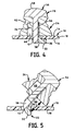
- the internal member 22 is inserted into the aperture 46 and the screw 54 is started into the threaded hole 56 enough to retain the internal member 22 in the aperture 46, as in Fig. 5.
- the size of the gap 68 between the clamping surface 52 of the external member 24 and the retaining portion 32 of the internal member 22 allows the internal member 22 to be pivoted into the slot 12.
- the clamping surface 52 is placed against the wall 18 of the portable article 10, and the screw 54 is tightened until the inner surface 30 of the retaining portion 32 is pulled against the inner surface 16 of the wall 18. Whether this capability can be utilized in any particular situation depends on the characteristics of the slot 12, such as how thick the wall 18 is at the slot 12 and whether there are any external components of the portable article 10 close enough to the slot to impede pivoting the security anchor 20 into the slot.
- the second advantage of the configuration of Fig. 4 is that the screw 54 makes it more difficult to remove the security anchor 20 from the slot 12 without disassembling the security anchor. If a person tries to remove the security anchor 20 of Fig. 2 by, for example, pivoting the security anchor 20 counterclockwise, the curve of the outer corner 38 of the junction of the slot engagement portion 34 and the retaining portion 32 will not necessarily provide the greatest deterrent to removal.
- the screw 54 of Fig. 6 extends vertically into the portable article 10, well below the level of the inner surface 16 of the wall 18. Since the screw 54 is vertical and not curved, it provides a greater impediment to pivoting the inner member 22 counterclockwise out of the slot 12 without first disassembling the security anchor 20.
- the external member 24 is designed to deny access to the head 58 of the screw 54 by having the security device 70, described below, cover enough of the aperture 46 to prevent removal of the screw 54.
- the screw head 58 may be external to the aperture 46, as in Fig. 4.
- the security device covers the screw head 58 itself to prevent removal of the screw 54.
- the anchor device 20 of the present invention provides an anchor 44 for removably attaching the security device that will be used to secure the portable article to a stationary object, such as a table.
- a knob 60 with an annular groove 62 The security device 70 has a head 72 with a mating groove 74 that slides into the annular groove 62. The circular nature of the annular groove 62 allows the security device 70 to be attached from any direction.
- the security device head 72 covers the aperture 46 into which the screw 54 is inserted, preventing access to the removable securement.
- the shape of the annular groove 62 may be whatever is necessary to securely mate with the security device head 72.
- Figs. 1-3 show the annular groove shape as rectangular.
- Fig. 4 shows the annular groove 62 with a curved shape. The curved shape is preferred if ball bearings are used to secure the security device head 72 to the knob 60.
- a second configuration of the anchor 44 also uses a knob 60 with an annular groove 62.
- the top of the knob 60 is the screw head 58 and the groove 62 is formed from a curve 76 in the external member 24 and the bottom surface 78 of the screw head 58.
- a third configuration of the anchor 44 shown in Fig. 7, includes a ring 64.
- a tether or cable lock can be fed through the ring 64, where the tether or cable lock will deny access to the attaching screw 54.
- a fourth configuration of the anchor 44 shown in Fig. 8, includes a screw 80 and washer 82 holding a rotatable shell 84.
- the shell 84 includes a pair of coaxial apertures 86 through which a tether or cable lock can be fed. The tether or cable lock prevents access to the screw 80 when installed.
- the components of the anchor 20 are preferably composed of materials that cannot be easily disabled.
- the preferred materials are stronger than the plastic case of the typical portable article so that the case will be destroyed before the anchor 20 of the present invention.
- the security anchor of Fig. 2 is installed by curling the retaining portion 32 and slot engaging portion 34 of the internal member 22 into the slot 12, fitting the external member aperture 46 onto the external member engaging portion 36 of the internal member 22, and securing the external member 24 to the internal member 22 with the screw 58.
- the security anchor of Fig. 4 is installed by first inserting the internal member 22 into the aperture 46 and starting the screw 54 into the threaded hole 56 enough to retain the internal member 22 in the aperture 46, as in Fig. 5. Then the retaining portion 32 of the internal member 22 is pivoted into the slot 12, and the screw 54 is tightened until the security anchor 20 is secured to the portable article 10.
Landscapes
- Engineering & Computer Science (AREA)
- Computer Hardware Design (AREA)
- Casings For Electric Apparatus (AREA)
Claims (10)
- Verankerungseinrichtung (20), die zur Verwendung mit einem tragbaren Artikel angepasst ist, der einen genormten Sicherheitsschlitz (12) aufweist, welche aufweist:wobei das interne Teil (22) einen Schlitzeingriffsbereich (34), einen Rückhaltebereich (32) und einen Externteil-Erfassungsbereich (36) aufweist, wobei der Schlitzeingriffsbereich (34) angepasst ist, innerhalb des Sicherheitsschlitzes (12) zu bleiben und der Rückhaltebereich (32) angepasst ist, innerhalb eines Artikels (8) zu bleiben und sich ungefähr in einem rechten Winkel von dem Schlitzeingriffsbereich (34) für einen Kontakt mit dem Artikel (18) erstreckt, und das externe Teil eine Klemmfläche (52) fiir einen Kontakt mit dem Artikel (18) und eine Öffnung (46) in der Klemmfläche (52) aufweist, um den Extemteil-Erfassungsbereich (36) aufzunehmen.ein inneres Teil (22);ein äußeres Teil (24);einen Anker (44), der angepasst ist, eine Sicherheitseinrichtung (70) aufzunehmen; undeine Sicherung (26) zum Sichern des externen Teils an dem internen Teil;
- Verankerungseinrichtung nach Anspruch 1, wobei die Sicherung (26) entfernbar ist und auf diese nicht zugegriffen werden kann, wenn die Sicherungseinrichtung (70) durch den Anker (44) aufgenommen ist, wobei die Sicherung eine entfernbare Schraube (54) aufweist, die sich durch die Öffnung (46) in das externe Teil in ein Gewindeloch (56) im internen Teil erstreckt, wobei die Schraube einen Schraubenkopf (58) zu Erfassen des externen Teils (24) aufweist.
- Verankerungseinrichtung nach Anspruch 2, wobei, wenn sich die Schraube (54) durch die Öffnung im externen Teil erstreckt und in das Gewindeloch im externen Teil läuft, die Lücke (68) zwischen der Klemmfläche (52) des externen Teils und dem Rückhaltebereich (32) des internen Teils groß genug ist, zuzulassen, dass das interne Teil im Schlitz gedreht wird.
- Verankerungseinrichtung nach Anspruch 2 oder 3, wobei - im installierten Zustand - das Gewindeloch (56, Fig. 4) sich vollständig durch das interne Teil erstreckt und die Schraube sich vollständig durch das Gewindeloch erstreckt.
- Verankerungseinrichtung nach Anspruch 2, wobei - im installierten Zustand - der Schraubenkopf (58, Fig. 2) innerhalb des externen Teils ist.
- Verankerungseinrichtung nach Anspruch 2, wobei - im installierten Zustand - der Schraubenkopf (58, Fig.4) außerhalb des externen Teils ist.
- Verankerungseinrichtung nach Anspruch 6, wobei der Anker (44) einen Knopf mit einer ringförmigen Nut (62, Fig.5) aufweist, die einerseits von einer Krümmung (76) in der oberen Fläche des externen Teils und andererseits von der Bodenfläche (78) des Schraubenkopfs (58) - im installierten Zustand - gebildet wird.
- Verankerungseinrichtung nach einem der Ansprüche 1 bis 6, wobei der Anker einen Knopf mit einer ringförmigen Nut (62, Fig. 4) im externen Teil aufweist.
- Verankerungseinrichtung nach einem der vorherigen Ansprüche, wobei das interne Teil Ohren (40) aufweist, die sich vom Externteil-Eingriffsbereich erstrecken, wobei die Ohren angepasst sind, zu verhindern, dass der Externteil-Eingriffsbereich des internen Teils in den Schlitz (12) eintritt.
- Verankerungseinrichtung nach einem der Ansprüche 1 bis 5 oder 9, wobei der Anker eine drehbare Hülle (84, Fig.8) aufweist, die ausgerichtete Öffnungen (86) hat, die angepasst sind, die Sicherheitseinrichtung aufzunehmen.
Applications Claiming Priority (3)
| Application Number | Priority Date | Filing Date | Title |
|---|---|---|---|
| US334570 | 1999-06-21 | ||
| US09/334,570 US6081974A (en) | 1999-06-21 | 1999-06-21 | Security anchor for portable articles |
| PCT/US2000/017107 WO2000079142A1 (en) | 1999-06-21 | 2000-06-21 | Security anchor for portable articles |
Publications (3)
| Publication Number | Publication Date |
|---|---|
| EP1203166A1 EP1203166A1 (de) | 2002-05-08 |
| EP1203166A4 EP1203166A4 (de) | 2002-08-28 |
| EP1203166B1 true EP1203166B1 (de) | 2005-11-02 |
Family
ID=23307818
Family Applications (1)
| Application Number | Title | Priority Date | Filing Date |
|---|---|---|---|
| EP00941617A Expired - Lifetime EP1203166B1 (de) | 1999-06-21 | 2000-06-21 | Sicherheitsverankerungsvorrichtung für tragbare gegenstände |
Country Status (4)
| Country | Link |
|---|---|
| US (2) | US6081974A (de) |
| EP (1) | EP1203166B1 (de) |
| DE (1) | DE60023709T2 (de) |
| WO (1) | WO2000079142A1 (de) |
Families Citing this family (47)
| Publication number | Priority date | Publication date | Assignee | Title |
|---|---|---|---|---|
| US6735990B1 (en) | 1992-01-24 | 2004-05-18 | Acco Brands, Inc. | Computer physical security device |
| US7143614B1 (en) | 1992-01-24 | 2006-12-05 | Acco Brands Usa Llc | Computer physical security device |
| US7201029B2 (en) | 1993-10-15 | 2007-04-10 | Acco Brands Usa Llc | Computer physical security device |
| US6212918B1 (en) | 1998-09-24 | 2001-04-10 | Benson Enterprises Incorporated | Locking mechanism for portable valuables |
| US6513350B1 (en) * | 2000-09-20 | 2003-02-04 | Acco Brands, Inc. | Computer physical security device |
| USD469006S1 (en) | 2001-01-26 | 2003-01-21 | Brant Monson | Bolt |
| USD465148S1 (en) | 2001-01-26 | 2002-11-05 | Brant Monson | Bolt |
| US6840704B1 (en) | 2001-01-26 | 2005-01-11 | Brant Monson | Quick release system for motorcycle backrests |
| US6543098B2 (en) * | 2001-03-02 | 2003-04-08 | Tektronix, Inc. | Printed circuit board mounting facility |
| US6449992B1 (en) * | 2001-07-31 | 2002-09-17 | Chun Te Yu | Combination lock device |
| US20030029208A1 (en) | 2001-08-13 | 2003-02-13 | Ralph Merrem | Portable electronic device physical security |
| USD466001S1 (en) | 2001-10-19 | 2002-11-26 | Brant Monson | Bolt |
| MXPA01013322A (es) * | 2001-12-19 | 2003-06-26 | Manuel Enrique Reinosa Servin | Dispositivo de sujecion para equipo de computo y equipo en general. |
| US6779370B2 (en) | 2002-02-27 | 2004-08-24 | Belkin Components | Security device, method of manufacturing the same, and method of operating the same |
| AU2003252175B2 (en) | 2002-07-24 | 2006-05-18 | Acco Brands Usa Llc | Lock for securing an article on display |
| IL154194A (en) * | 2003-01-30 | 2009-09-22 | Meir Avganim | Arrangement for tying a portable object to a stationary object by a cable |
| US7044348B2 (en) * | 2003-03-27 | 2006-05-16 | Lear Corporation | Modular storage system |
| WO2005010303A2 (en) | 2003-07-23 | 2005-02-03 | Acco Brands, Inc. | Computer physical security device with retractable cable |
| US8456836B2 (en) | 2004-05-10 | 2013-06-04 | Think Products, Inc. | Spring loaded security slot attachment for portable device security |
| US8223488B2 (en) | 2004-05-10 | 2012-07-17 | Think Products, Inc. | Locking assembly for electronic tablet and other devices |
| US8837144B1 (en) | 2004-05-10 | 2014-09-16 | Think Products, Inc. | Locking assembly for electronic tablet and other devices |
| US7724520B2 (en) | 2004-05-10 | 2010-05-25 | Peter Allen | Protruding lock for notebook computer or other personal electronic device |
| US8139356B2 (en) * | 2004-05-10 | 2012-03-20 | Peter Allen | Plunger security lock and personal electronic device configured to be secured by the plunger lock |
| US7324333B2 (en) * | 2004-05-10 | 2008-01-29 | Peter Allen | Lock for notebook computer or other personal electronic device |
| US7315443B2 (en) * | 2004-05-10 | 2008-01-01 | Peter Allen | Notebook computer locking base |
| US7443665B2 (en) | 2004-05-10 | 2008-10-28 | Peter Allen | Lock for notebook computer or other personal electronic device |
| US7499270B2 (en) | 2004-05-10 | 2009-03-03 | Peter Allen | Lock for portable music player or other personal electronic device |
| US7415852B1 (en) | 2004-10-06 | 2008-08-26 | Acco Brands Usa Llc | Tubular lock with theft deterrent |
| US20060081021A1 (en) * | 2004-10-20 | 2006-04-20 | Acco Brands, Inc. | Security device including linearly moving member |
| US7500371B2 (en) | 2005-11-18 | 2009-03-10 | Acco Brands Usa Llc | Locking device with passage |
| US7540451B2 (en) * | 2006-09-05 | 2009-06-02 | Se-Kure Controls, Inc. | System for securing a cable to a portable article |
| GB2446144A (en) * | 2007-02-01 | 2008-08-06 | Anthony Shea | Lock assembly for outboard motor |
| US20100192642A1 (en) | 2007-05-25 | 2010-08-05 | Acco Brands Usa Llc | Security system including adapter |
| US7614266B2 (en) | 2007-10-15 | 2009-11-10 | Acco Brands Usa Llc | Security apparatus with reset mechanism |
| AU2010253755B2 (en) * | 2009-05-29 | 2015-08-27 | Acco Brands Usa Llc | Security apparatus including attachment device |
| US8182181B2 (en) * | 2009-11-05 | 2012-05-22 | Coleman Douglas A | Cargo tie-down |
| US8640510B1 (en) | 2010-12-12 | 2014-02-04 | Jay S. Derman | Interface member for lock system and method |
| USD651889S1 (en) | 2011-04-19 | 2012-01-10 | Acco Brands Usa Llc | Security apparatus |
| US9410344B2 (en) | 2011-06-14 | 2016-08-09 | ACCO Brands Corporation | Protective case for physically securing a portable electronic device |
| US8869573B2 (en) | 2011-06-14 | 2014-10-28 | ACCO Brands Corporation | Protective case for physically securing a portable electronic device |
| US8640511B1 (en) | 2011-09-13 | 2014-02-04 | Jay S. Derman | Low profile lock interface system and method |
| US8726703B1 (en) * | 2012-01-20 | 2014-05-20 | Jay S Derman | Low profile lock interface system and method |
| US8899080B1 (en) | 2012-03-21 | 2014-12-02 | Jay S Derman | Cinch lock apparatus and method |
| US8783073B1 (en) | 2012-04-04 | 2014-07-22 | Jay S. Derman | Apparatus for securing a portable electronic device |
| DE202013011843U1 (de) | 2013-04-04 | 2014-08-18 | ITAB Harr GmbH | Mechanische Sicherungsvorrichtung |
| US9469238B1 (en) | 2015-01-28 | 2016-10-18 | Douglas A. Coleman | Load restraint device |
| US20230332733A1 (en) * | 2022-02-10 | 2023-10-19 | Steven Wai-Tong Cheng | Device compatible mounting stand |
Family Cites Families (14)
| Publication number | Priority date | Publication date | Assignee | Title |
|---|---|---|---|---|
| US598022A (en) * | 1898-01-25 | Necticut | ||
| US3303735A (en) * | 1965-02-01 | 1967-02-14 | Christopher L Fisher | Hook bolt and nut assembly |
| US3512226A (en) * | 1968-03-12 | 1970-05-19 | Textron Inc | Plastic hook and eye |
| US3463525A (en) * | 1968-04-26 | 1969-08-26 | Schaefer Equip | Securing safety equipment to railroad cars by means of a blind hook bolt |
| US4131204A (en) * | 1975-11-20 | 1978-12-26 | Seiz Corporation | Positive-locking releasable connector for storage rack having vertically adjustable load supports |
| US4490065A (en) * | 1982-12-16 | 1984-12-25 | Combustion Engineering, Inc. | Splice locking device |
| JPH0136418Y2 (de) * | 1985-11-02 | 1989-11-06 | ||
| JPH0436655Y2 (de) * | 1986-12-12 | 1992-08-28 | ||
| US6000251A (en) * | 1992-01-24 | 1999-12-14 | Acco Brands, Inc. | Computer physical security device |
| US5447045A (en) * | 1994-05-25 | 1995-09-05 | Manufacturing Technology Resources Inc. | Apparatus for locking a closed notebook computer on a computer support |
| KR0121851Y1 (ko) * | 1995-04-24 | 1998-08-17 | 김광호 | 피시 도난 방지 장치 |
| US5685049A (en) * | 1995-09-15 | 1997-11-11 | Wu; Hung-Ming | Alloy button for jeans |
| US5941485A (en) * | 1997-08-01 | 1999-08-24 | Shakespeare Company | Assembly for mounting a removable step to a hollow utility pole |
| US6212918B1 (en) * | 1998-09-24 | 2001-04-10 | Benson Enterprises Incorporated | Locking mechanism for portable valuables |
-
1999
- 1999-06-21 US US09/334,570 patent/US6081974A/en not_active Expired - Lifetime
-
2000
- 2000-06-21 WO PCT/US2000/017107 patent/WO2000079142A1/en not_active Ceased
- 2000-06-21 DE DE60023709T patent/DE60023709T2/de not_active Expired - Lifetime
- 2000-06-21 EP EP00941617A patent/EP1203166B1/de not_active Expired - Lifetime
- 2000-06-28 US US09/605,913 patent/US6317936B1/en not_active Expired - Lifetime
Also Published As
| Publication number | Publication date |
|---|---|
| DE60023709D1 (de) | 2005-12-08 |
| US6081974A (en) | 2000-07-04 |
| EP1203166A4 (de) | 2002-08-28 |
| WO2000079142A1 (en) | 2000-12-28 |
| EP1203166A1 (de) | 2002-05-08 |
| DE60023709T2 (de) | 2006-07-20 |
| US6317936B1 (en) | 2001-11-20 |
Similar Documents
| Publication | Publication Date | Title |
|---|---|---|
| US6317936B1 (en) | Security anchor for portable articles | |
| US5502989A (en) | Computer physical security device | |
| US6305199B1 (en) | Computer slot security adaptor | |
| EP2435650B1 (de) | Sicherheitsvorrichtung mit anbringungsvorrichtung | |
| US6564602B2 (en) | Shielded pushbutton lock | |
| US20040180566A1 (en) | Securing device having bypass interface | |
| US6755056B2 (en) | Computer slot security adaptor | |
| US7111479B2 (en) | Computer physical security device | |
| US5660451A (en) | Computer component security device with parallel table securing means | |
| US4094173A (en) | Vehicle lock | |
| JP3607295B2 (ja) | コンピュータの物理的安全装置 | |
| US8061169B2 (en) | Locking system with hidden keyed access | |
| US5167395A (en) | Automobile battery locking device | |
| US5277600A (en) | Electrical plug safety lock | |
| GB2158662A (en) | Locking means for plug and socket assembly | |
| US5947038A (en) | Security box apparatus | |
| WO2000043684A1 (en) | Threaded hole locking device | |
| CA2519843C (en) | Locking system with hidden keyed access | |
| JP4336201B2 (ja) | サーフボードロック | |
| GB2358888A (en) | Fixing device for decorative external housing | |
| US20040261472A1 (en) | Locking mechanism for a personal computer | |
| US12410637B2 (en) | Anti-theft device for cradle mounted device which removably receives an audio/video device | |
| GB2262119A (en) | Lockable access cover | |
| KR20010017815A (ko) | 체결용 봉인장치 | |
| KR200165518Y1 (ko) | 현관문 시건장치 |
Legal Events
| Date | Code | Title | Description |
|---|---|---|---|
| PUAI | Public reference made under article 153(3) epc to a published international application that has entered the european phase |
Free format text: ORIGINAL CODE: 0009012 |
|
| 17P | Request for examination filed |
Effective date: 20020121 |
|
| AK | Designated contracting states |
Kind code of ref document: A1 Designated state(s): AT BE CH CY DE DK ES FI FR GB GR IE IT LI LU MC NL PT SE |
|
| A4 | Supplementary search report drawn up and despatched |
Effective date: 20020715 |
|
| AK | Designated contracting states |
Kind code of ref document: A4 Designated state(s): AT BE CH CY DE DK ES FI FR GB GR IE IT LI LU MC NL PT SE |
|
| RIC1 | Information provided on ipc code assigned before grant |
Free format text: 7F 16B 41/00 A, 7F 16B 21/00 B, 7E 05B 73/00 B, 7E 05B 63/00 B, 7F 16B 5/02 B |
|
| GRAP | Despatch of communication of intention to grant a patent |
Free format text: ORIGINAL CODE: EPIDOSNIGR1 |
|
| 18D | Application deemed to be withdrawn |
Effective date: 20040608 |
|
| GRAS | Grant fee paid |
Free format text: ORIGINAL CODE: EPIDOSNIGR3 |
|
| 18RA | Request filed for re-establishment of rights before grant |
Effective date: 20050315 |
|
| RAP1 | Party data changed (applicant data changed or rights of an application transferred) |
Owner name: ACCO BRANDS, INC. |
|
| D18D | Application deemed to be withdrawn (deleted) | ||
| GRAA | (expected) grant |
Free format text: ORIGINAL CODE: 0009210 |
|
| AK | Designated contracting states |
Kind code of ref document: B1 Designated state(s): DE FR GB IT |
|
| REF | Corresponds to: |
Ref document number: 60023709 Country of ref document: DE Date of ref document: 20051208 Kind code of ref document: P |
|
| RAP2 | Party data changed (patent owner data changed or rights of a patent transferred) |
Owner name: ACCO BRANDS USA LLC |
|
| ET | Fr: translation filed | ||
| PLBE | No opposition filed within time limit |
Free format text: ORIGINAL CODE: 0009261 |
|
| STAA | Information on the status of an ep patent application or granted ep patent |
Free format text: STATUS: NO OPPOSITION FILED WITHIN TIME LIMIT |
|
| 26N | No opposition filed |
Effective date: 20060803 |
|
| PGFP | Annual fee paid to national office [announced via postgrant information from national office to epo] |
Ref country code: IT Payment date: 20080627 Year of fee payment: 9 |
|
| PG25 | Lapsed in a contracting state [announced via postgrant information from national office to epo] |
Ref country code: IT Free format text: LAPSE BECAUSE OF NON-PAYMENT OF DUE FEES Effective date: 20090621 |
|
| REG | Reference to a national code |
Ref country code: FR Ref legal event code: PLFP Year of fee payment: 17 |
|
| REG | Reference to a national code |
Ref country code: FR Ref legal event code: PLFP Year of fee payment: 18 |
|
| REG | Reference to a national code |
Ref country code: FR Ref legal event code: PLFP Year of fee payment: 19 |
|
| PGFP | Annual fee paid to national office [announced via postgrant information from national office to epo] |
Ref country code: DE Payment date: 20190521 Year of fee payment: 20 |
|
| PGFP | Annual fee paid to national office [announced via postgrant information from national office to epo] |
Ref country code: FR Payment date: 20190522 Year of fee payment: 20 |
|
| PGFP | Annual fee paid to national office [announced via postgrant information from national office to epo] |
Ref country code: GB Payment date: 20190522 Year of fee payment: 20 |
|
| REG | Reference to a national code |
Ref country code: DE Ref legal event code: R071 Ref document number: 60023709 Country of ref document: DE |
|
| REG | Reference to a national code |
Ref country code: GB Ref legal event code: PE20 Expiry date: 20200620 |
|
| PG25 | Lapsed in a contracting state [announced via postgrant information from national office to epo] |
Ref country code: GB Free format text: LAPSE BECAUSE OF EXPIRATION OF PROTECTION Effective date: 20200620 |