The present invention relates to an organic
electroluminescence element.
An organic electroluminescence element (hereinafter
referred to as an organic EL element) is expected as a new
self-light emission type element. The organic EL element has
such a stacked structure that a carrier transport layer (an
electron transport layer or a hole transport layer) and a
luminescent layer are formed between a hole injection electrode
and an electron injection electrode.
An electrode material which has a large work function
such as gold or ITO (indium-tin oxides) is employed for the
hole injection electrode, while a material which has a small
work function such as Mg (magnesium) or Li (lithium) is
employed for the electron injection electrode.
Organic materials are employed for a hole transport
layer, a luminescent layer and an electron transport layer.
Materials which have the property of p-type semiconductors are
used for the hole transport layer, while those which have the
property of n-type semiconductors are used for the electron
transport layer. The luminescent layer also has carrier
transportability such as electron transportability or hole
transportability and is composed of an organic material ,which
emits fluorescence or phosphorescence.
The hole injection electrode, the hole transport layer,
the luminescent layer, the electron transport layer and the
electron injection electrode are stacked in this order so as
to form an organic EL element.
Such function layers as the hole transport layer, the
electron transport layer and the luminescent layer are formed
of a plurality of layers, or alternatively, some of those layers
are deleted depending on the organic materials to be employed.
In such an element structure as shown by Chihaya Adachi
et al. in Appl. Phys. Lett., Vol. 55, pp. 1489 - 1491(1989),
for example, there exists only two organic layers of a
luminescent layer and an electron transport layer between a
hole injection electrode and an electron injection electrode.
This is because the luminescent layer also serves as a hole
transport layer since the luminescent layer made of NSD as a
luminescent material has excellent hole transportability.
In such an element structure as shown by C. W. Tang et
al. in Appl. Phys. Lett., Vol. 51, pp. 913 - 915(1987), the
structure is formed of two organic layers of a hole transport
layer and a luminescent layer. In this case, Tris(8-hydroxyquinolinato)aluminum
(hereinafter referred to as Alq)
of the luminescent layer serves to both emit light and
transport electrons.
On the other hand, such an element structure as shown
by S. A. Van Slyke et al. in Appl. Phys. Lett., Vol. 69, pp.
2160 - 2162(1996) is formed of three organic layers of a hole
injection layer, a hole transport layer and a luminescent layer.
In this case, the hole injection layer is composed of copper
phthalocyanine and serves the same as the hole transport layer.
That is, there exists two hole transport layers in the whole
element.
Thus, free adjustments can be made in the number of layers
constituted by the electron transport layer, hole transport
layer and luminescent layer in dependence on the organic
materials to be employed.
While the organic EL element is formed of the respective
function layers of the electron transport layer, hole transport
layer and luminescent layer, the organic materials now in use
have insufficient transportability of electrons or holes.
This provides such problems as low luminance or low luminous
efficiency.
In particular, the electron transport layer has become
the cause of such problems. As a material which has been
widely used, Alq as described above is employed as an electron
transport material. This organic material can also be employed
as a luminescent material and can easily form films by vacuum
vapor deposition. Further, this material has such excellent
characteristics as high stability after film formation and
high heat resistivity. However, the material provides poor
carrier transportability of holes and electrons, exhibiting
poor luminescent characteristics.
The disadvantage of Alq is that Alq deteriorates while
being energized. (Refer to Hany Aziz et al., Science, Vol. 283,
pp. 1900 - 1902(1999).) This results from deterioration of
a molecule itself, which occurs if holes flow into Alq.
In Appl. Phys. Lett., Vol. 75, pp. 172 - 174(1999), Vi-En
Choong et al. have proposed employing N,N'-Di(naphthalen-1-yl)-N,N'-diphenyl-benzidine
(hereinafter referred to as
NPB), which is a hole transportable material, for Alq in order
to solve the above disadvantage of Alq; however, such an
approach has not yet overcome the above described low luminous
efficiency.
An object of the present invention is to provide an
organic electroluminescence element capable of obtaining
high luminance and high luminous efficiency.
According to an aspect of the present invention, an
organic electroluminescence element comprises a hole injection
electrode, an electron transport layer, a luminescent layer
and an electron injection electrode in this order, wherein at
least one layer out of the electron transport layer and the
luminescent layer includes a host material and a carrier
transportable dopant, and the carrier transportable dopant is
composed of a compound having a carbazole group or a derivative
of the compound.
The compound having the carbazole group and its
derivative are liable to be crystallized. Thus, if the
electron transport layer or the luminescent layer is formed
with single employment of the compound having the carbazole
group or its derivative, or if such a compound or its derivative
is employed for the electron transport layer or the luminescent
layer as a host material of a doping method, it results in
very lower durability and lower luminous efficiency.
In the organic electroluminescence element according to
the present invention, the electron transport layer or the
luminescent layer includes the carrier transportable dopant
composed of the compound having the carbazole group or the
derivative thereof, thereby attaining high luminance and high
luminous efficiency.
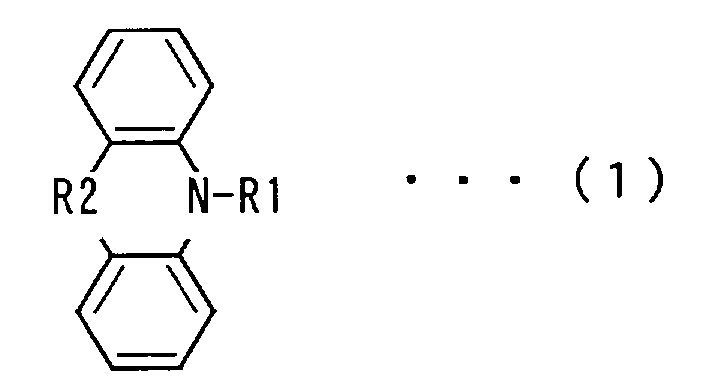
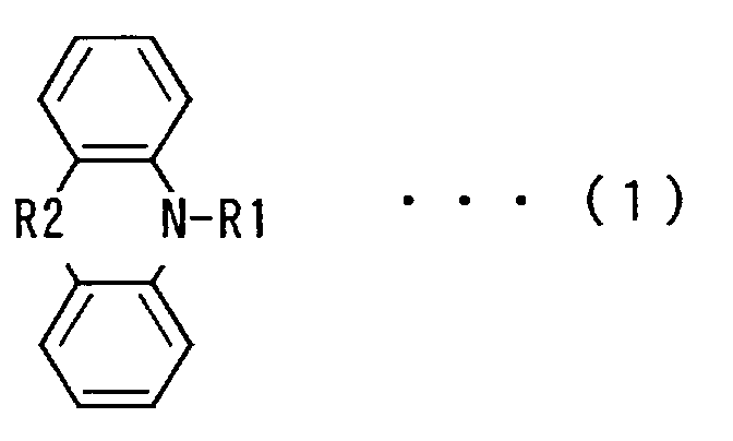
The carrier transportable dopant may have such a
molecular structure as expressed in the following chemical
formula (1). In the formula (1), R1 may be a substituent, and
R2 may be a bonding site or a substituent.
The carrier transportable dopant may be 4,4'-Bis(carbazol-9-yl)-biphenyl
(hereinafter referred to as CBP).
In this case, higher luminance and higher luminous efficiency
are attained.
The carrier transportable dopant may be 4,4',4"-Tris(carbazol-9-yl)-triphenylamine
(hereinafter referred to
as TCTA). In this case, higher luminance and higher luminous
efficiency are obtained.
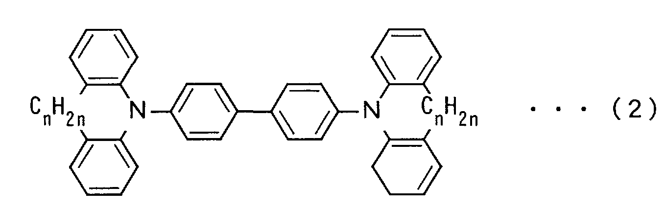
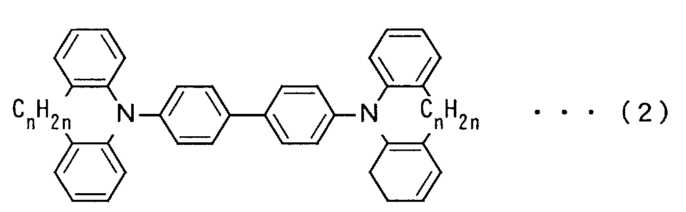
The carrier transportable dopant is a compound expressed
in the following chemical formula (2)where n may be integers
of one or more. In this case, higher luminance and higher
luminous efficiency are attained.
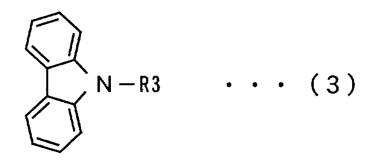
The carrier transportable dopant may be a compound having
such a molecular structure as expressed in the following
chemical formula (3)where R3 is hydrogen, alkyl group, phenyl
group or naphthyl group. In this case, higher luminance and
higher luminous efficiency are effected.
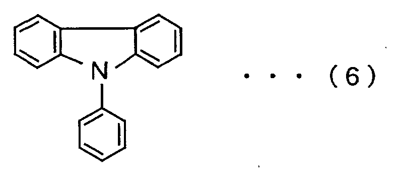
The carrier transportable dopant may be 9-phenylcarbazol.
In this case, higher luminance and higher luminous efficiency
are attained.
It is preferable that the content of the carrier
transportable dopant in at least one layer out of the electron
transport layer and the luminescent layer is 50 % by weight
or less for a host material. If the carrier transportable
dopant is more than 50 % by weight, it acts as the host material
rather than the dopant, thereby facilitating crystallization.
Further, it is preferable that the content of the carrier
transportable dopant is 1 % by weight or more for the host
material. This leads to enhancement in luminescent
characteristics and carrier transportability.
The host material may include a complex of an 8-hydroxyquinoline
derivative and metal. This effects high
luminance and high luminous efficiency.
The metal in the complex may be aluminum, zinc, magnesium
or beryllium. It is particularly preferable that the metal
in the complex is aluminum or zinc, thereby attaining high
luminance and high luminous efficiency.
The 8-hydroxyquinoline derivative in the complex may be
Tris(8-hydroxyquinolinato)aluminum (hereinafter referred to
as Alq).
The 8-hydroxyquinoline derivative in the complex may be
Tris(4-methyl-8-hydroxyquinolinato)aluminum.
The 8-hydroxyquinoline derivative in the complex may be
Bis(8-hydroxyquinolinato)zinc.
The 8-hydroxyquinoline derivative in the complex may be
Tris(4-hydroxyphenanthridinato)aluminum.
The 8-hydroxyquinoline derivative may be Tris(2-methyl-8-hydroxyquinolinato)aluminum.
At least one layer out of the electron transport layer
and the luminescent layer may include 50 % by weight or more
of the host material. Moreover, the content of the host
material is preferably 99 % by weight or less.
The electron transport layer may include the host
material and the carrier transportable dopant. Also in this
case, luminance and luminous efficiency become enhanced.
Further, the luminescent layer may include the host
material and the carrier transportable dopant. Luminance and
luminous efficiency improve also in this case. The luminescent
layer may further include a luminescent dopant.
The luminescent layer may further include an energy
movable dopant. This results in satisfactorily high luminance
and high luminous efficiency.
The foregoing and other objects, features, aspects and
advantages of the present invention will become more apparent
from the following detailed description of the present
invention when taken in conjunction with the accompanying
drawings.
Fig. 1 is a model diagram showing one example of the
structure of an organic EL element.
Fig. 2 is a model diagram showing another example of the
structure of an organic EL element.
Fig. 1 is a model diagram showing one example of the
structure of an organic electroluminescence element
(hereinafter referred to as an organic EL element).
In an organic EL element 100 shown in Fig. 1, a hole
injection electrode (anode) 2 made of a transparent conductive
film is formed on a glass substrate 1. A hole transport layer
3 made of an organic material, a luminescent layer 4 made of
an organic material and an electron transport layer 5 made of
an organic material are formed in turn on the hole injection
electrode 2. An electron injection electrode (cathode) 6 is
formed on the electron transport layer 5.
In the organic EL element 100 shown in Fig. 1, the electron
transport layer 5 includes an electron transport material ( a
host material) and a carrier transportable dopant. The carrier
transportable dopant is contained 1 % by weight to 50 % by weight
for the electron transport material, preferably 1 % by weight
to 10 % by weight.
As the carrier transportable dopant, a compound having
a carbazole group or a derivative of the compound is employed.
It is, in particular, preferable that the carrier
transportable dopant has such a molecular structure as
expressed in the above chemical formula (1).
Especially if R2 is a bonding site in the formula (1),
the carbazole gruop is composed.
As the carrier transportable dopant, for example, it is
possible to employ CBP having such a molecular structure as
expressed in an chemical formula (4) below , TCTA having a
molecular structure of a chemical formula (5) as shown below
or the compound having the molecular structure of the above
formula (2).
In the above chemical formula (2),it is preferable to
satisfy n = 1 to 5, and in the case where n = 2 is satisfied,
4,4'-Bis(dihydro-dibenz-azepin-1-yl)-biphenyl (hereinafter
referred to as AZB) is provided.
Alternatively, the compound having the molecular
structure of the above chemical formula (3) may be employed
as the carrier transportable dopant. In the formula (3), R3
is -CnH2n+1 (n = 0 to 5), a phenyl group or a naphthyl group.
The compound having the molecular structure of the
formula (3) may be, for example, 9-phenylcarbazol which has
such a molecular structure as expressed in the following
chemical formula (6).
As the electron transport material, a complex of an
8-hydoxyquinoline derivative and metal is employed. The metal
in the complex is aluminum, zinc, magnesium or beryllium, and
especially aluminum or zinc is preferred.
As the electron transport material, for example, it is
possible to employ Alq having a molecular structure of a
chemical formula (7) below , Tris(4-methyl-8-hydroxyquinolinato)aluminum
having a molecular structure of
a chemical formula (8) below, Bis(8-hydroxyquinolinato)zinc
having a molecular structure of a chemical formula (9) below,
Tris(4-hydroxyphenanthridinato)aluminum having a molecular
structure of the following chemical formula (10), Tris(2-methyl-8-hydroxyquinolinato)aluminum
having a molecular
structure of the following chemical formula (11), etc.
In the organic EL element 100 of Fig. 1, the electron
transport layer 5 includes the carrier transportable dopant
composed of the compound having the carbazole group or its
derivative, thereby attaining high luminance and high luminous
efficiency.
Fig. 2 is a model diagram showing another example of the
structure of an organic electroluminescence element.
In an organic EL element 101, a hole injection electrode
(anode) 2 made of a transparent conductive film is formed on
a glass substrate 1. A first hole transport layer 7 made of
an organic material, a second hole transport layer 8 made of
an organic material and a luminescent layer 9 made of an organic
material are formed in turn on the hole injection electrode
2. An electron injection electrode (cathode) 6 is formed on
the luminescent layer 9.
In the organic EL element 101 shown in Fig. 2, the
luminescent layer 9 includes a host material and a carrier
transportable dopant. The carrier transportable dopant is
contained 1 % by weight to 50 % by weight for the host material,
preferably 1 % by weight to 10 % by weight.
As the carrier transportable dopant, a compound having
a carbazole group or a derivative of the compound is employed.
In particular, it is preferable that the carrier
transportable dopant has the molecular structure expressed in
the above chemical formula (1). Especially, if R2 in the
formula (1) is a bonding site, a carbazole group is composed.
As the carrier transportable dopant, for example, it is
possible to employ CBP having the molecular structure of the
above chemical formula (4), TCTA having the molecular structure
of the above formula (5), or the compound having the molecular
structure of the above formula (2).
In the above formula (2), it is preferable to satisfy
n = 1 to 5 . In the case where n = 2 is satisfied, 4,4'-Bis(dihydro-dibenz-azepin-1-yl)-biphenyl
(hereinafter
referred to as AZB) is provided.
Alternatively, the compound having the molecular
structure of the above formula (3) may be used as the carrier
transportable dopant. R3 in the formula (3) is -CnH2n+1 (n =
0 to 5 ), a phenyl group or a naphthyl group.
The compound having the molecular structure of the
formula (3) may be, for example, 9-phenylcarbazol having the
molecular structure of the above formula (6).
A complex of an 8-hydroxyquinoline derivative and metal
is employed as a host material. The metal contained in the
complex is aluminum, zinc, magnesium or beryllium. Especially,
aluminum or zinc is preferred.
As the host material, for example, it is possible to
employ Alq having the molecular structure of the above chemical
formula (7), Tris(4-methyl-8-hydroxyquinolinato)aluminum
having the molecular structure of the above formula (8),
Bis(8-hydroxyquinolinato)zinc having the molecular structure
of the above formula (9), Tris(4-hydroxyphenanthridinato)aluminum
having the molecular
structure of the above formula (10), Tris(2-methyl-8-hydroxyquinolinato)aluminum
having the molecular structure of
the above formula (11), etc.
The
luminescent layer 9 may further be doped with a
luminescent dopant. As the luminescent dopant, it is possible
to employ, for example, Rubrene having a molecular structure
expressed in a chemical formula (12) below or 2-(1,1-Dimethylethyl)-6-(2-(2,3,6,7-tetrahydro-1,1,7,7-tetramethyl-1H,5H-benzo(ij)quinolizin-9-yl)ethenyl)-4H-pyran-4H-ylidene)propanedinitrile
(hereinafter referred to
as DCJTB) having a molecular structure expressed in the
following chemical formula (13).
The luminescent layer 9 may further be doped with an
energy movable dopant. This leads to satisfactorily high
luminance and high luminous efficiency. As the energy movable
dopant, Rubrene, for example, can be employed.
The luminescent layer 9 may contain 50 % by weight or
more of the host material. Moreover, the content of the host
material is preferably 99 % by weight or less.
In the organic EL element 101 of Fig. 2, the luminescent
layer 9 includes the carrier transportable dopant composed of
the compound having the carbazole group or its derivative,
thereby attaining high luminance and high luminous efficiency.
The structure of the organic EL element is not limited
to the above described structures but can employ various
structures. For example, three layers of the hole injection
layer, the hole transport layer and the luminescent layer may
be provided between the hole injection electrode 2 and the
electron injection electrode 6. Only two layers of the
luminescent layer and the electron transport layer may be
provided between the hole injection electrode 2 and the
electron injection electrode 6.
Application of voltage between the hole injection
electrode 2 and the electron injection electrode 6 causes the
luminescent layer 5 of the organic EL element 100, 101 to become
luminous and then allows light to be emitted from the reverse
face of the glass substrate 1.
[Examples]
Organic EL elements in inventive examples 1 to 12 and
those in comparative examples 1 to 6 were manufactured to
measure luminescent characteristics as will now be described.
(Cases where carrier transportable dopants were employed
for an electron transport layer)
In inventive examples 1 to 7 and comparative examples
1 to 3, examinations were made on effects in luminescent
characteristics when carrier transportable dopants were
employed for an electron transport layer.
[Inventive example 1]
An organic El element in the inventive example 1 has such
a structure as shown in Fig. 1. A hole injection electrode
(anode) 2 is composed of indium-tin oxides (ITO). A
hole
transport layer 3 has a thickness of 500 Å and is composed of
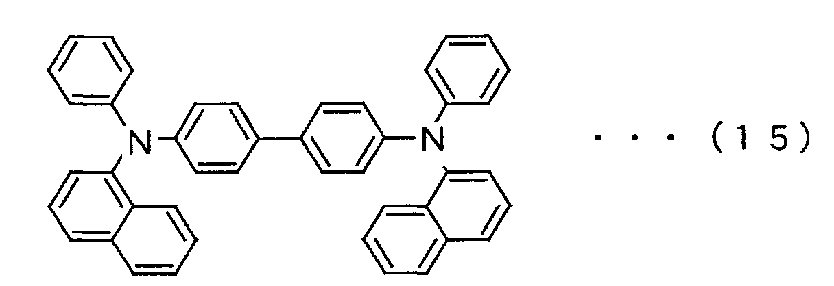
2TNATA having a molecular structure of a chemical formula (14)
shown below. A
luminescent layer 4 having a thickness of 150
Å contains NPB having a molecular structure of a chemical
formula (15) as a host material and also contains as a
luminescent dopant 5 % by weight of Rubrene for the host
material. An
electron transport layer 5 having a thickness
of 350 Å contains Alq as an electron trasport material (host
material) and also contains as a carrier
transportable dopant
4 % by weight of CBP for the electron transport material. An
electron injection electrode (cathode) 6 is composed of a MgIn
alloy (a ratio of 10 to 1) with a thickness of 2000 Å.
The organic EL element having the above described
structure was manufactured by the following process. First,
the hole injection electrode 2 composed of indium-tin oxides
(ITO) was formed on a glass substrate 1. The glass substrate
1, on which the hole injection electrode 2 was formed, was then
cleaned with a neutral detergent, and thereafter cleaned by
ultrasonic cleaning in acetone for 10 minutes and in ethanol
for 10 minutes. Further, the surface of the glass substrate
1 was cleaned in an ozone cleaner.
After cleaning, the hole transport layer 3, the
luminescent layer 4, the electron transport layer 5 and the
electron injection electrode 6 were stacked in turn on the hole
injection electrode 2 made of the above ITO by vacuum vapor
deposition. The vacuum vapor deposition of these layers and
electrodes was made under conditions of ordinary temperature
at the degree of vacuum 1 × 10⁻⁶ Torr without control of
substrate temperature.
The hole injection electrode 2 of this organic EL element
was applied with a positive bias voltage, and the electron
injection electrode 6 was applied with a negative voltage, so
as to measure luminescent characteristics.
[Inventive example 2]
An organic EL element in the inventive example 2 was
manufactured under the same conditions as applied to the
organic EL element in the inventive example 1 except that TCTA
was substituted for CBP as the carrier transportable dopant
to be employed for the electron transport layer 5.
[Inventive example 3]
An organic EL element in the inventive example 3 was
manufactured under the same conditions as applied to the
organic EL element in the inventive example 1 except that AZB
was substituted for CBP as the carrier transportable dopant
to be employed for the electron transport layer 5.
[Inventive example 4]
An organic EL element in the inventive example 4 was
fabricated under the same conditions as applied to the organic
EL element in the inventive example 1 except that Tris(4-methyl-8-hydroxyquinolinato)aluminum
was substituted for Alq
as the electron transport material (host material) to be
employed for the electron transport layer 5.
[Inventive example 5]
An organic EL element in the inventive example 5 was
fabricated under the same conditions as applied to the organic
EL element in the inventive example 1 except that Bis(8-hydroxyquinolinato)zinc
was substituted for Alq as the
electron transport material (host material) of the electron
transport layer 5.
[Inventive example 6]
An organic EL element in the inventive example 6 was
manufactured under the same conditions as applied to the
organic EL element in the inventive example 1 except that
Tris(4-hydroxyphenanthridinato)aluminum was substituted for
Alq as the electron transport material (host material) to be
employed for the electron transport layer 5.
[Inventive example 7]
An organic EL element in the inventive example 7 was
fabricated under the same conditions as applied to the organic
EL element in the inventive example 1 except that 9-phenylcarbazol
was substituted for CBP as the carrier
transportable dopant to be employed for the electron transport
layer 5.
[Comparative example 1]
An organic EL element in the comparative example 1 was
manufactured under the same conditions as applied to the
organic EL element in the inventive example 1 except that NPB
was substituted for CBP as the carrier transportable dopant
to be used for the electron transport layer 5.
[Comparative example 2]
An organic EL element in the comparative example 2 was
manufactured under the same conditions as applied to the
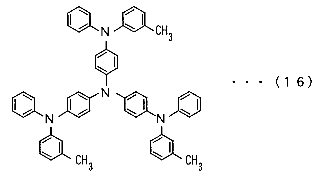
organic EL element in the inventive example 1 except that MTDATA
having a molecular structure of a chemical formula (16) as below
was substituted for CBP as the carrier transportable dopant
to be used for the
electron transport layer 5.
An organic EL element in the comparative example 3 was
fabricated under the same conditions as applied to the organic
El element in the inventive example 1 except that no carrier
transportable dopant was employed.
The materials of the electron transport layer in the
organic EL elements of the above described inventive examples
1 to 7 and the comparative examples 1 to 3 are shown in Table
1.
| | Electron Transportlayer |
| | Electron Transport Material | Carrier Transportable Dopant |
| Inventive Exmaple 1 | Alq | CBP |
| Inventive Exmaple 2 | Alq | TCTA |
| Inventive Exmaple 3 | Alq | AZB |
| Inventive Exmaple 4 | Tris(4-menthly-8-hydroxyquinolinato)aluminium | CBP |
| Inventive Exmaple 5 | Bis(8-Hydroxyquinolinato) zinc | CBP |
| Inventive Exmaple 6 | Tris(4-hydroxyphenanthridinato) aluminium | CBP |
| Inventive Exmaple 7 | Alq | 9-phenylcarbozol |
| Comparative Exmaple |
| 1 | Alq | NPB |
| Comparative Exmaple |
| 2 | Alq | MTDATA |
| Comparative Exmaple |
| 3 | Alq | None |
Results of measurement in luminescent characteristics
as to the organic EL elements of the inventive examples 1 to
7 and the comparative examples 1 to 3 are shown in Table 2.
| Name of Elemnt | Efficiency (at 100cd/m2) | Luminescent Color |
| Inventive Example 1 | 9.0cd/A | Yellow |
| Inventive Example 2 | 8.2cd/A | Yellow |
| Inventive Example 3 | 7.6cd/A | Yellow |
| Inventive Example 4 | 9.5cd/A | Yellow |
| Inventive Example 5 | 8.1cd/A | Yellow |
| Inventive Example 6 | 7.9cd/A | Yellow |
| Inventive Example 7 | 8.5cd/A | Yellow |
| Comparative Example 1 | 7.4cd/A | Yellow |
| Comparative Example 2 | 4.6cd/A | Yellow |
| Comparative Example 3 | 6.6cd/A | Yellow |
As shown in Table 2, the organic EL elements of the
inventive examples 1 to 7 and those of the comparative examples
1 to 3 emitted yellow light.
Further, as can be understood from Table 2, the luminous
efficiencies in the organic EL elements of the inventive
examples 1, 4, 5 and 6 employing CBP as the carrier transportable
dopant, the organic EL element of the inventive example 2
employing TCTA, that of the inventive example 3 employing AZB
and that of the inventive example 7 employing 9-phenylcarbazol
became higher than the luminous efficiencies in the organic
EL element of the comparative example 1 employing NPB as the
carrier transportable dopant, that of the comparative example
2 employing MTDATA and that of the comparative example 3
employing no carrier transportable dopant.
When Alq was employed as the electron transportable
material, in particular, the luminous efficiencies in the
respective cases where CBP was employed as the carrier
transportable dopant, where 9-phenycarbazol was employed,
where TCTA was employed and where AZB was employed became higher
in this order.
Further, when CBP was employed as the carrier
transportable dopant, high luminous efficiencies of 8 cd/A or
more were achieved in any respective cases where Alq,
Tris(4-methyl-8-hydroxyquinolinato)aluminum, Bis(8-hydroxyquinolinato)zinc
or Tris(4-hydroxyphenanthridinato)aluminum
was employed as the electron
transport material.
It was apparent from the above results that the luminances
and the luminous efficiencies became highly enhanced in any
organic EL elements, in which the compounds having the
carbazole gruop or their derivatives were employed as the
carrier transportable dopant of the electron transport layer,
as compared to those in which the other organic materials were
employed as the carrier transportable dopant of the electron
transport layer.
(Cases where carrier transportable dopants were
employed for a luminescent layer)
Examinations were made on effects in luminescent
characteristics in the cases where carrier transportable
dopants were employed for the luminescent layer in inventive
examples 8 to 12 and comparative examples 4 to 6.
[Inventive example 8]
An organic EL element of the inventive example 8 has such
a structure as shown in Fig. 2. A hole injection electrode
(anode) 2 is composed of indium-tin oxides (ITO). A first hole
transport layer 7 has a thickness of 500 Å and is composed of
2TNATA. A second hole transport layer 8 has a thickness of
150 Å and is composed of NPB. A luminescent layer 9 has a
thickness of 350 Å and contains Alq as a host material
(luminescent material) and 6 % by weight of CBP as a carrier
transportable dopant for the host material. An electron
injection electrode (cathode) 6 is composed of a MgIn alloy
(a ratio of 10 to 1) having a thickness of 2000 Å.
Conditions under which the organic EL element of the
inventive example 8 was manufactured were the same as those
applied to the organic EL element of the inventive example 1.
The hole injection electrode 2 of this organic EL element
was applied with a positive bias voltage, and the electron
injection electrode 6 was applied with a negative bias voltage,
so as to measure luminescent characteristics.
[Comparative example 4]
An organic EL element of the comparative example 4 was
manufactured under the same conditions as applied to the
organic EL element of the inventive example 8 except that no
carrier transportable dopant was employed for the luminescent
layer 9.
[Inventive example 9]
An organic EL element of the inventive example 9 was
fabricated under the same conditions as applied to the organic
EL element of the inventive example 8 except that Rubrene as
a luminescent dopant was doped 5 % by weight for Alq into the
luminescent layer 9.
[Comparative example 5]
An organic EL element of the comparative example 5 was
manufactured under the same conditions as applied to the
organic EL element of the inventive example 9 except that no
carrier transportable dopant was employed for the luminescent
layer 9.
[Inventive example 10]
An organic EL element of the inventive example 10 was
fabricated under the same conditions as applied to the organic
EL element of the inventive example 9 except that the
luminescent layer 9 was doped with 2 % by weight, for Alq, of
DCJTB being a red luminescent dopant to be employed as a
luminescent dopant.
That is to say, the luminescent layer 9 contains Alq as
the host material, DCJTB as the red luminescent dopant, Rubrene
as the energy movable dopant and CBP as the carrier
transportable dopant.
Since the wavelength of fluorescence of Rubrene is 566
nm which is shorter than the wavelength of fluorescence of DCJTB
being 649 nm, energy moves from Rubrene having large excitation
energy to DCJTB having small excitation energy. Thus, Rubrene
does not emit light, but DCJTB emits red light in this
luminescent layer 9.
[Inventive example 11]
An organic EL element of the inventive example 11 was
manufactured under the same conditions as applied to the
organic EL element of the inventive example 10 except that the
luminescent layer 9 was doped with 6 % by weight of TCTA for
Alq in place of CBP as the carrier transportable dopant.
[Comparative example 6]
An organic EL element of the comparative example 6 was
manufactured under the same conditions as applied to the
organic EL element of the inventive example 10 except that no
carrier transportable dopant was employed for the luminescent
layer 9.
[Inventive example 12]
An organic EL element of the inventive example 12 was
fabricated under the same conditions as applied to the organic
EL element of the inventive example 10 except that Tris(2-methyl-8-hydroxyquinolinato)aluminum
was employed in place of
Alq as the host material for the luminescent layer 9.
Table 3 shows the materials of the electron transport
layer in the respective organic EL elements of the above
described inventive examples 8 to 12 and comparative examples
4 to 6.
| | Luminescent Layer |
| | Host Material | Luminescent Dopant | Energy Movable Dopant | Carrier Transportable Dopant |
| Inventive Example 8 | Alq | | | CBP |
| Comparative Example 4 | Alq | | | None |
| Inventive Example 9 | Alq | Rubrene | | CBP |
| Comparative Example 5 | Alq | Rubrene | | None |
| Inventive Example 10 | Alq | DCJTB | Rubrene | CBP |
| Inventive Example 11 | Alq | DCJTB | Rubrene | TCTA |
| Comparative Example 6 | Alq | DCJTB | Rubrene | None |
| Inventive Example 12 | Tris(2-menthyl-8-hydroxyquinolinato)aluminium | DCJTB | Rubrene | CBP |
Table 4 shows the results of luminescent characteristics
as to the respective organic EL elements of the inventive
examples 8 to 12 and comparative examples 4 to 6.
| Name of Elemnt | Efficiency (at 100cd/m2) | Luminescent Color |
| Inventive Example 8 | 5.0cd/A | Green |
| Comparative Example 4 | 3.6cd/A | Green |
| Inventive Example 9 | 7.3cd/A | Yellow |
| Comparative Example 5 | 5.4cd/A | Yellow |
| Inventive Example 10 | 2.1cd/A | Red |
| Inventive Example 11 | 2.0cd/A | Red |
| Comparative Example 6 | 1.5cd/A | Red |
| Inventive Example 12 | 1.9cd/A | Red |
As shown in Table 4, the organic EL element of the
inventive example 8 and that of the comparative example 4 both
emitted green light. It is understood from the comparison
between the inventive example 8 and the comparative example
4 that luminous efficiency becomes enhanced by employment of
CBP as the carrier transportable dopant for the luminescent
layer 9.
In addition, the organic EL element of the inventive
example 9 and that of the comparative example 5 emitted yellow
light. It is understood from the comparison between the
inventive example 9 and the comparative example 5 that luminous
efficiency becomes higher by employment of CBP as the carrier
transportable dopant for the luminescent layer 9.
Moreover, the respective organic EL elements of the
inventive examples 10, 11 and 12 and the comparative example
6 emitted red light. It is understood from the comparison among
the inventive examples 10, 11 and the comparative example 6
that luminous efficiency becomes enhanced by employment of CBP
or TCTA as the carrier transportable dopant for the luminescent
layer 9.
It is also understood from the inventive example 12 that
luminous efficiency becomes higher by employment of
Tris(2-methyl-8-hydroxyquinolinato)aluminum in place of Alq
as the host material for the luminescent layer 9.
It is apparent from the above results that the luminance
and the luminous efficiency become highly enhanced in the
organic EL elements employing the compounds having the
carbazole group as the carrier transportable dopants as
compared with those employing other organic materials as the
carrier transportable dopants of the electron transport layer.
Although the present invention has been described and
illustrated in detail, it is clearly understood that the same
is by way of illustration and example only and is not to be
taken by way of limitation, the spirit and scope of the present
invention being limited only by the terms of the appended
claims.