EP1202066B1 - Method for dispense verification - Google Patents
Method for dispense verification Download PDFInfo
- Publication number
- EP1202066B1 EP1202066B1 EP02000782A EP02000782A EP1202066B1 EP 1202066 B1 EP1202066 B1 EP 1202066B1 EP 02000782 A EP02000782 A EP 02000782A EP 02000782 A EP02000782 A EP 02000782A EP 1202066 B1 EP1202066 B1 EP 1202066B1
- Authority
- EP
- European Patent Office
- Prior art keywords
- fluid
- dispense
- receiver
- source
- signal
- Prior art date
- Legal status (The legal status is an assumption and is not a legal conclusion. Google has not performed a legal analysis and makes no representation as to the accuracy of the status listed.)
- Expired - Lifetime
Links
- 238000000034 method Methods 0.000 title claims abstract description 26
- 238000012795 verification Methods 0.000 title description 6
- 239000012530 fluid Substances 0.000 claims abstract description 156
- 230000005670 electromagnetic radiation Effects 0.000 claims abstract description 28
- 230000002123 temporal effect Effects 0.000 claims abstract description 16
- 230000002411 adverse Effects 0.000 claims description 7
- 238000001514 detection method Methods 0.000 claims description 5
- 230000000694 effects Effects 0.000 claims description 4
- 230000002401 inhibitory effect Effects 0.000 claims 2
- 239000000523 sample Substances 0.000 description 17
- 239000008280 blood Substances 0.000 description 8
- 210000004369 blood Anatomy 0.000 description 8
- 239000000203 mixture Substances 0.000 description 7
- 238000012360 testing method Methods 0.000 description 5
- 241000725303 Human immunodeficiency virus Species 0.000 description 4
- 239000012472 biological sample Substances 0.000 description 3
- 239000003153 chemical reaction reagent Substances 0.000 description 3
- 230000007423 decrease Effects 0.000 description 3
- 230000001419 dependent effect Effects 0.000 description 2
- 239000000428 dust Substances 0.000 description 2
- 230000006870 function Effects 0.000 description 2
- 238000005259 measurement Methods 0.000 description 2
- 238000012544 monitoring process Methods 0.000 description 2
- 230000009467 reduction Effects 0.000 description 2
- 230000004044 response Effects 0.000 description 2
- 230000008054 signal transmission Effects 0.000 description 2
- 238000001228 spectrum Methods 0.000 description 2
- 230000004913 activation Effects 0.000 description 1
- XAGFODPZIPBFFR-UHFFFAOYSA-N aluminium Chemical compound [Al] XAGFODPZIPBFFR-UHFFFAOYSA-N 0.000 description 1
- 229910052782 aluminium Inorganic materials 0.000 description 1
- 238000013459 approach Methods 0.000 description 1
- 238000004159 blood analysis Methods 0.000 description 1
- 238000004140 cleaning Methods 0.000 description 1
- 238000010276 construction Methods 0.000 description 1
- 230000007547 defect Effects 0.000 description 1
- 238000002405 diagnostic procedure Methods 0.000 description 1
- 238000001704 evaporation Methods 0.000 description 1
- 230000005484 gravity Effects 0.000 description 1
- 238000005286 illumination Methods 0.000 description 1
- 230000000670 limiting effect Effects 0.000 description 1
- 238000003754 machining Methods 0.000 description 1
- 239000000463 material Substances 0.000 description 1
- 238000012986 modification Methods 0.000 description 1
- 230000004048 modification Effects 0.000 description 1
- 230000005693 optoelectronics Effects 0.000 description 1
- 239000002245 particle Substances 0.000 description 1
- 230000008569 process Effects 0.000 description 1
- 238000012545 processing Methods 0.000 description 1
- 230000035945 sensitivity Effects 0.000 description 1
- 239000000126 substance Substances 0.000 description 1
- 238000013024 troubleshooting Methods 0.000 description 1
Images

Classifications
-
- G—PHYSICS
- G01—MEASURING; TESTING
- G01N—INVESTIGATING OR ANALYSING MATERIALS BY DETERMINING THEIR CHEMICAL OR PHYSICAL PROPERTIES
- G01N35/00—Automatic analysis not limited to methods or materials provided for in any single one of groups G01N1/00 - G01N33/00; Handling materials therefor
- G01N35/10—Devices for transferring samples or any liquids to, in, or from, the analysis apparatus, e.g. suction devices, injection devices
- G01N35/1009—Characterised by arrangements for controlling the aspiration or dispense of liquids
- G01N35/1016—Control of the volume dispensed or introduced
-
- G—PHYSICS
- G01—MEASURING; TESTING
- G01N—INVESTIGATING OR ANALYSING MATERIALS BY DETERMINING THEIR CHEMICAL OR PHYSICAL PROPERTIES
- G01N35/00—Automatic analysis not limited to methods or materials provided for in any single one of groups G01N1/00 - G01N33/00; Handling materials therefor
- G01N35/10—Devices for transferring samples or any liquids to, in, or from, the analysis apparatus, e.g. suction devices, injection devices
- G01N35/1009—Characterised by arrangements for controlling the aspiration or dispense of liquids
- G01N35/1016—Control of the volume dispensed or introduced
- G01N2035/102—Preventing or detecting loss of fluid by dripping
Definitions
- Embodiments of the present invention generally relate to a method for verifying dispense of a fluid. More specifically, the embodiments relate to a method for verifying fluid dispense in an automated instrument.
- Automated instruments are available to perform a number of tasks.
- One such automated instrument is an analytical instrument.
- An analytical instrument can perform tests, such as medical diagnostic tests, on a sample. For example, such tests may identify the AIDS virus in a blood sample or other item of interest in a biological sample.
- an analytical instrument may mix the biological sample with a substance, such as a reagent and the like.
- these reagents may be fluids.
- the fluids may be supplied to the biological sample within the medical instrument by a fluid system.
- the fluid system may include a source of fluid, a pump, a dispense nozzle and a conduit fluidly connecting those elements.
- the source of fluid may be a container and the like.
- the pump operates to move fluid from the container toward the dispense nozzle through the conduit.
- the sample which may be held in a suitable container, is positioned adjacent the dispense nozzle. When the pump is operated, fluid from the container leaves the nozzle and enters the sample container. Movement of the fluid into the container, if desired, can cause the fluid and the sample to mix.
- a given instrument may perform a blood analysis.
- the instrument adds a predetermined volume of a fluid to a predetermined volume of a blood sample.
- the fluid reacts with the blood sample. Because of the reaction between the sample and the fluid, an electromagnetic signal or light is sent from the mixture of sample and fluid.
- a detector in the instrument sees or reads the light sent from the mixture.
- Appropriate elements of the instrument such as a computer and the like, interpret the information obtained by the detector and provide an operator with information about the blood sample.
- the test performed may be to see if a unit of blood were infected with the AIDS virus. Assuming that the blood is infected with the AIDS virus, adding too little or too much fluid to the blood sample may result in the instrument telling the operator that the unit of blood is not infected with the AIDS virus.
- the conduit may contain a bubble.
- the conduit itself may be bent or damaged.
- the pump may not function properly.
- a drop of fluid may form on an end of the dispense nozzle. These causes may not be detected by simply monitoring the length of time of pump operation or of fluid leaving the dispense nozzle. Accordingly, it can be appreciated that it is desirable to have an element in the instrument for verifying that the proper, predetermined amount of fluid has left the dispense nozzle during operation of the analytical instrument.
- a method for verifying dispense of a fluid from a fluid exiting end of a nozzle is known from DE-A-4211003 .
- Embodiments disclosed herein provide a method for verifying dispense of a fluid from a dispense nozzle as defined in claim 1.
- Fig. 1 illustrates one embodiment 10 of an apparatus and a method for verifying dispense of a fluid 12 from a dispense nozzle 14.
- Dispense verification refers to obtaining information about the status of a fluid dispense, detecting a major hanging drop of fluid, checking temporal duration of a dispense, etc.
- dispense verification utilizes an electromagnetic radiation intensity measurement, possibly coupled with a temporal measurement.
- fluid 12 may be understood to be a reagent, other fluids are also possible. It may be desirable to locate an apparatus at every fluid addition location apt to cause a false result or inaccurate information being given to an instrument operator. Illustrating by example, in an analytical instrument, dispense verification apparatus may be located where particles, conjugates and/or probes are added to sample and where washes occur.
- the embodiment 10 comprises a source 16 of electromagnetic radiation and a receiver 18 operatively associated with the dispense nozzle 14.
- the source 16 and the receiver 18 are disposed with respect to the dispense nozzle 14 such that flow of fluid 12 from the nozzle 14 passes through a path 20 of electromagnetic radiation from the source 16 to the receiver 18.
- the path 20 passes through an ambient fluid, such as air. No lenses or filters are required. As will be discussed in further detail later, passage of fluid 12 through the path 20 allows for dispense verification.
- the source 16 and the receiver 18 are predetermined such that the receiver 18 generates a signal responsive to electromagnetic radiation sent from the source 16.
- the source 16 may be a light emitting diode and the like.
- the source 16 is capable of emitting electromagnetic radiation of about 900nm (infrared).
- the receiver 18, in an exemplary embodiment, may be a phototransistor and the like. If the source 16 were a diode emitting electromagnetic radiation at about 900nm, then the receiver 18 would be chosen such that a peak sensitivity of the receiver 18 would be in substantially the same range of the electromagnetic spectrum.
- the source 16 is an SEP8706-002 and the receiver 18 is an SDP8406-003, both being available from Honeywell, MICRO SWITCH, Optoelectronics Division of Richardson, Texas.
- the source 16 and the receiver 18 are electrically connected by a wire 22 to other supporting electronics, such as a controller 24 through a preamplifier 26, for instance.
- the source 16 is supplied with power at a substantially constant level.
- all embodiments may be compared against a common threshold, discussed later.
- the preamplifier 26 presents a relatively high input impedance to match the impedance of the receiver 18.
- the preamplifier 26 also presents a relatively low impedance to match the impedance of the controller 24.
- the relatively low impedance facilitates signal transmission along conduit 22 toward controller 24.
- the controller 24 comprises a processor, such as a Motorola (Schaumburg, Illinois) 68HC11F1 and the like, and a digital-to-analog converter, such as a 7228A, available from Analog Devices, Inc. of Norwood, Massachusetts, and the like. If multiple apparatuses 10 were provided, then the controller 24 can include a multiplexer, such as one handling about six outputs and about 12 inputs.
- the outputs would drive, up to about 5mA, two source 16/receiver 18 pairs connected electrically in series.
- Such a circuit can incorporate current feedback to provide a substantially linear response.
- the multiplexer is predetermined to have a frequency response sufficient for about 98% setting in about 130 microseconds. In this manner, switching of source 16 drives and multiplexer input signals would be appropriately chosen such that the 12 inputs could be read, approximately, every 1.6 msec.
- the preamplifier 26 drives two source 16/receiver 18 pairs selectively with two predetermined electrical signals.
- a first pair of source 16/receiver 18 is designated the "A" pair, while the other pair is designated the "B" pair.
- the A and B pairs are electrically connected in series with the preamplifier 26.
- the preamplifier 26 drives the A and B pairs at a predetermined electrical signal appropriate for the A pair.
- the output of the receiver 18 in the A pair is monitored.
- the preamplifier 26 drives the A and B pairs at a predetermined electrical signal for the B pair.
- the output of the B receiver 18 is monitored.
- the electrical signal driving all of the sources 16 is not constant.
- the A electrical signal is applied to the source 16 and the output of the associated receiver 18 is monitored after it settles.
- the B electrical signal is applied and the output of the B receiver 18 is monitored. This process can repeat at a rate of about 1250 times per second.
- each receiver 18 output is monitored about 625 times each second. Accordingly, during a dispense cycle, the receiver 18 output can be monitored about 80 times while the output is below the threshold. This can result in an error tolerance of about one percent.
- the controller 24 may be provided with access, such as an RS232 port, to a computer for monitoring, controlling and trouble shooting the apparatus 10.
- the computer or other electronic element operatively associated with the access may provide a feedback signal to an operator indicative of the status of dispense of fluid 12 from the dispense nozzle 14.
- the source 16 and the receiver 18 are offset from the path of fluid 12 flow from the dispense nozzle 14 by screens 28A and 28B, respectively.
- the screens 28A and 28B are constructed and located to reduce the chance that fluid 12 flowing from the dispense nozzle 14 might reach the source 16 or the receiver 18. If fluid 12 were to reach either the source 16 or the receiver 18, then the embodiment 10 may not operate as intended.
- the screens 28A and 28B may also be used if it were desired to avoid cleaning the source 16 and/or the receiver 18. In this embodiment, the screens 28A and 28B could be cleaned instead of the source 16 and receiver 18.
- Fig. 2 illustrates an embodiment 30 of an apparatus for verifying dispense of fluid 12 from dispense nozzle 14 which does not comprise screens 28A and 28B.
- the embodiment 30 is substantially similar to the embodiment 10 of Fig. 1 , hence the like reference numerals for similar structures. Both embodiments 10 and 30 function substantially the same.
- the dispense nozzle 14 comprises a bore 32 having a diameter D of about 0,762 mm (0.030 inches). Therefore, a stream of fluid 12 leaving the dispense nozzle 14 has a diameter of about 0,762 mm (0.030 inches).
- the source 16, which illuminates relevant portions of the receiver 18 with electromagnetic radiation, and the receiver 18 are mutually exposed through an aperture having a diameter A of about 1,575 mm (0.062 inches).
- the apertures may be formed by a suitable technique, such as machining and the like, in a mounting bracket, formed from a suitable material such as aluminum and the like, operatively associated with the source 16 and the receiver 18.
- the apertures define dimensions of a latitudinal cross section of the path 20 of electromagnetic radiation from the source 16 to the receiver 18.
- a longitudinal axis of the path 20 is offset from a fluid-exiting end 34 of the dispense nozzle 14 by a specific, predetermined distance O, shown in Fig. 3 .
- the distance O is about 2,54 mm (0.10 inches).
- the distance O is chosen so that the embodiments 10 and 30 are able to sense a significant volume of fluid 12 depending from the end 34 of the dispense nozzle 14. Put in another way, the distance O is chosen such that the embodiments 10 and 30 detect a major drop of fluid 12 and avoid a minor drop of fluid 12 depending or hanging from the end 34 of the nozzle 14.
- a major drop of fluid 12 contains a volume of fluid 12 sufficient to significantly adversely affect dispense of an intended volume of fluid 12 from the nozzle 14, whereas a minor drop of fluid 12 does not have sufficient volume of fluid 12 to significantly adversely affect dispense of an intended volume of fluid 12.
- minor hanging drops the likelihood of sensing a dispense incorrectly can be reduced.
- detecting major hanging drops is desirable because a major hanging drop can significantly affect dispense of fluid 12 from the dispense nozzle 14. If the dispense of fluid 12 were significantly affected, then it is possible that the instrument associated with the dispense nozzle 14 could give the instrument operator incorrect information about a sample being tested.
- Detection of a major hanging drop is also dependent upon a threshold applied to a signal generated by the receiver 18.
- the threshold is a predetermined percentage of electromagnetic signal (i.e. electromagnetic intensity) sent from the source 16 and received by the receiver 18.
- the threshold may be considered to represent a portion of the electromagnetic signal sent from the source 16 and blocked from reaching the receiver 18 by fluid 12 depending or dispensed from the dispense nozzle 14.
- the value of the threshold is predetermined such that the embodiments 10 and 30 can detect fluid dispense status and a major hanging drop and ignore a minor hanging drop. Determination of the threshold will be discussed in detail later.
- the embodiments 10 and 30, as well as all supporting electronics, are constructed to provide feedback dependent upon a comparison of electromagnetic intensity received by the receiver 18 with the threshold, thereby indicative of fluid dispense status and/or hanging drops, to the operator.
- the embodiments 10 and 30 could indicate presence of a hanging drop if the receiver 18 was illuminated by the source 16 at a level of less than about 90% of the level of illumination of the receiver 18 by the source 16 when no fluid 12 is present (i.e. a quiescent state).
- the embodiments 10 and 30 would indicate an erroneous dispense if the electromagnetic radiation received by the receiver 18 were to fall by about 10% from its quiescent state.
- the embodiments 10 and 30 would detect a drop of fluid 12, having a fluid volume as small as about 10 ⁇ l, for example, depending from the end 34 of the nozzle 14. In this manner, the effects of things which cause a dispense of fluid 12 from the nozzle 14 to decrease or trail off relatively slowly at the end of a dispense cycle, rather than the dispense cycle ending abruptly, can be detected.
- the source 16 is energized to produce an electromagnetic signal of predetermined characteristics.
- the electromagnetic signal travels from the source 16 along the path 20 to the receiver 18.
- the source 16 generates this electromagnetic signal substantially continuously during operation of the embodiments 10 and 30. If the embodiments 10 and 30 were included in an analytical instrument, then, in one embodiment, the source 16 would generate the electromagnetic signal throughout substantially the entire duration of analytical instrument operation.
- the receiver 18 is at the quiescent state. The electromagnetic signal received by the receiver 18 at this time is defined as the quiescent or reference signal.
- the substantially continuous operation of the source 16 allows for substantially fail-safe operation of the embodiments.
- the electromagnetic signal travels from the source 16 to the receiver 18 substantially continuously so that any deviation, as determined by the controller 24, in transmitted signal intensity, received by the receiver 18 can be used to provide feedback indicative of fluid 12 dispense from the nozzle 14 to the operator.
- the intensity of the electromagnetic signal transmitted by the source 16 and received the receiver 18 is used to determine the threshold discussed earlier. If there were multiple embodiments 10 and 30 in a given instrument, then all of the embodiments may be set to the same threshold. In an exemplary embodiment, because the flow of fluid 12 from the nozzle 14 during an intended fluid dispense cycle will pass through about half of the path 20 of electromagnetic radiation from the source 16 to the detector 18, the threshold may be selected to be about 75% of the quiescent state signal.
- the source 16 driving signal is adjusted prior to dispense of fluid 12 from the dispense nozzle 14.
- the source 16 driving signal is adjusted so that the quiescent signal is at a desired, predetermined level above the threshold.
- the source 16 driving signal can be adjusted within the range of a maximum and a minimum source 16 driving signal associated with the relevant source 16. If it were not possible to adjust the source 16 driving signal such that the quiescent signal is above the threshold by the desired amount, then an error message may be reported to an operator. Thus, functionality of the associated source 16/receiver 18 pair is verified.
- a major hanging drop is detected. Therefore, it may be desirable to set the threshold substantially within the range of about 80% to about 90% of the quiescent signal.
- the exact value of the threshold may depend on a number of factors, such as physical dimensions of the embodiments 10 and 30, characteristics of the fluid 12, etc.
- the threshold value may be determined by and stored in memory, such as a RAM, ROM, EPROM, SRAM and the like running appropriate routines, present in or associated with the controller 24.
- the controller 24 may update the threshold as necessary, thereby possibly allowing for obstructions, such as dust, other than fluid 12 in the path 20. These obstructions may accumulate over time, thereby making updating of the threshold desirable.
- fluid 12 dispense cycles can begin. As fluid 12 exits the dispense nozzle 14, the fluid 12 passes through the path 20 and correspondingly reduces the intensity of the electromagnetic signal reaching the receiver 18. The electromagnetic intensity received by the receiver 18 is monitored by the controller 24.
- the controller 24 may contain a timer to monitor duration of the reduction in received electromagnetic intensity. In these embodiments, the controller 24 monitors the time interval during which the electromagnetic intensity received by the receiver 18 is reduced below the predetermined threshold. The end of the dispense cycle is determined by the intensity received by the receiver 18 returning to a value greater than the threshold. The time between the moment the received intensity falls below the threshold and the moment the received intensity rises above the threshold is an actual temporal duration of the dispense cycle. This actual temporal duration is compared to a predetermined, expected temporal duration of the dispense cycle, which may be determined empirically. The expected temporal duration may depend on fluid 12 pump tolerances, conduit length from pump to the end 34 of the dispense nozzle 14, etc.
- an expected temporal duration may be about 124 msec. to about 144 msec. If the two temporal durations were substantially the same, then the controller 24 can cause feedback indicative of a proper dispense to be sent to the operator. If the actual and expected durations were not substantially the same, then the controller 24 can cause feedback indicative of an improper dispense to be sent to the operator.
- an electronic signal generated by the receiver 18 responsive to the electromagnetic signal sent by the source 16 during a proper dispense is shown in Fig. 4 .
- the threshold is set at about 90% of the quiescent signal Q and the expected temporal duration for a proper dispense is substantially within the range of 124 and 144 msec.
- the dispense cycle begins, labelled "X" in Fig. 4 , and fluid 12 flowing from the dispense nozzle 14 blocks a portion of the path 20.
- the fluid 12 reduces the intensity of the electromagnetic signal received by the receiver 18.
- the received intensity is reduced sufficiently such that it falls below the predetermined threshold value. This reduction in received intensity lasts for about 138 msec (actual temporal duration).
- the dispense cycle ends, indicated by "Y” in Fig. 4
- the received intensity increases, rises above the threshold value and approaches the quiescent signal Q.
- the controller 24 compares the actual and expected temporal durations. Because the two durations are substantially identical, this dispense is a proper dispense. If desired, the controller 24 can cause a relevant feedback signal to be sent to the operator.
- Improper dispenses can have a number of causes.
- One of the causes may be a gas, i.e. air bubble and the like, in the fluid 12 path from a fluid 12 stock container to the end 34 of the dispense nozzle 14.
- gases may cause gas to be present in the fluid path.
- the fluid 12 system may have been improperly "primed"
- the fluid 12 stock container may be almost empty, connections in the fluid 12 system may leak, fluid 12 may be restricted, there may be effects due to siphoning, etc.
- the actual temporal duration may be shortened. This can occur without changing substantially the volume of fluid 12 dispensed from the dispense nozzle 14.
- the gas in the line may be compressed during initial activation of a pump forcing fluid 12 through the line supplying the dispense nozzle 14, thereby possibly causing a delay in beginning the dispense.
- the velocity of the fluid 12 leaving the end 34 of the dispense nozzle 14 may be greater than the fluid velocity generated by the pump.
- the increased fluid 12 velocity can cause the desired volume of fluid 12 to leave the dispense nozzle 14 before the expiration of the expected temporal duration. Also, the increased fluid 12 velocity can cause fluid 12 to splash into unintended places.
- Build-up of fluid 12 residue which may be caused by fluid 12 evaporating from the end 34 of the nozzle 14, may direct fluid 12 from the end 34 of the dispense nozzle 14 in an unintended direction. Misdirection of fluid 12 from the end 34 of the dispense nozzle 14 during a dispense cycle may result in an improper dispense which is also detectable by the embodiment 10.
- the embodiment 10 can also verify that fluid 12 was dispensed from the dispense nozzle 14 in an intended path or direction.
- Another cause of improper dispenses may be a drop of fluid 12 depending or hanging from the end 34 of the dispense nozzle.
- the hanging drop may be formed by fluid pressure being relieved through the dispense nozzle 14. This may be caused by a "kink" or other restriction in the fluid line supplying fluid 12 to the dispense nozzle 14.
- a hanging drop may become a restriction to fluid 12 leaving the nozzle 14 through the end 34.
- the fluid 12 comprising the drop may dry on the dispense nozzle 14.
- fluid 12 hanging from the end 34 of the nozzle 14 in the form of a drop may fall off of the end 34 of the nozzle 14 at an unadvantageous time. The falling drop may cause erroneous information to be given to the operator. Thus, it is recommended that all data associated with tests involving an improper dispense be discarded.
- an electronic signal generated by the receiver 18 responsive to the electromagnetic signal sent by the source 16 during an improper dispense is shown in Fig. 5 .
- the threshold and the expected temporal durations are assumed to be the same as described above.
- the improper dispense in this example, is the result of a major hanging drop.
- the major hanging drop may have been caused by fluid 12 slowing leaking from the end 34 of the dispense nozzle 14. This may be indicative of a defect in the nozzle 14 or in the conduit supplying fluid 12 to the nozzle 14.
- the received signal is at about the quiescent signal. As time progresses, more fluid 12 leaks from the end 34 of the nozzle 14. A drop begins to form at the end 34. The drop of fluid 12 directs stray light back into the path 20 of electromagnetic radiation from the source 16 to the receiver 18. The direction of stray light into the path 20 causes the received intensity to increase, as shown at B.
- the received intensity increases until a portion of the drop of fluid 12 depending from the end 34 of the nozzle 14 begins to obstruct a portion of the path 20 between the source 16 and the receiver 18. At this point C, the received intensity of electromagnetic intensity begins to decrease. The received intensity decreases until the drop of fluid 12 is sufficient to substantially focus or direct electromagnetic radiation from the source 16 onto the receiver 18. As shown, the received intensity increases due to the redirection effected by the drop of fluid 12 hanging from the end 34 of the dispense nozzle 14.
- the size of the hanging drop continues to grow as more and more fluid 12 leaks from the dispense nozzle 14.
- the size of the drop increases until forces of the system, e.g. gravity, surface tension, adhesion, etc., are insufficient to maintain the drop of fluid 12 on the end 34 of the dispense nozzle 14.
- forces of the system e.g. gravity, surface tension, adhesion, etc.
- the drop falls off of the end 34 of the dispense nozzle 14.
- the received intensity increases, labelled F, toward the quiescent signal. Because fluid 12 continues to leak from the end 34 of the nozzle 14, the above-described behavior repeats.
- any conditions relevant to a fluid 12 dispense from the dispense nozzle 14 can be monitored by the embodiments 10 and 30 with appropriate modifications to the disclosed structures.
- the distance between the end 34 of the dispense nozzle 14 and the longitudinal mid line of the path 20 may be determined to allow detection of minor hanging drops.
- the threshold may be predetermined to allow detection of air bubbles, clots, inhomogeneities, etc. in the dispensed fluid 12 as it flows from the end 34 of the dispense nozzle 14.
Landscapes
- General Health & Medical Sciences (AREA)
- General Physics & Mathematics (AREA)
- Life Sciences & Earth Sciences (AREA)
- Chemical & Material Sciences (AREA)
- Analytical Chemistry (AREA)
- Biochemistry (AREA)
- Health & Medical Sciences (AREA)
- Immunology (AREA)
- Physics & Mathematics (AREA)
- Pathology (AREA)
- Automatic Analysis And Handling Materials Therefor (AREA)
- Application Of Or Painting With Fluid Materials (AREA)
- Loading And Unloading Of Fuel Tanks Or Ships (AREA)
- Infusion, Injection, And Reservoir Apparatuses (AREA)
- Sampling And Sample Adjustment (AREA)
Abstract
Description
- Embodiments of the present invention generally relate to a method for verifying dispense of a fluid. More specifically, the embodiments relate to a method for verifying fluid dispense in an automated instrument.
- Automated instruments are available to perform a number of tasks. One such automated instrument is an analytical instrument. An analytical instrument can perform tests, such as medical diagnostic tests, on a sample. For example, such tests may identify the AIDS virus in a blood sample or other item of interest in a biological sample.
- To perform such tests, an analytical instrument may mix the biological sample with a substance, such as a reagent and the like. In some embodiments, these reagents may be fluids. The fluids may be supplied to the biological sample within the medical instrument by a fluid system. The fluid system may include a source of fluid, a pump, a dispense nozzle and a conduit fluidly connecting those elements. The source of fluid may be a container and the like. The pump operates to move fluid from the container toward the dispense nozzle through the conduit. The sample, which may be held in a suitable container, is positioned adjacent the dispense nozzle. When the pump is operated, fluid from the container leaves the nozzle and enters the sample container. Movement of the fluid into the container, if desired, can cause the fluid and the sample to mix.
- Illustrating further by example, a given instrument may perform a blood analysis. The instrument adds a predetermined volume of a fluid to a predetermined volume of a blood sample. The fluid reacts with the blood sample. Because of the reaction between the sample and the fluid, an electromagnetic signal or light is sent from the mixture of sample and fluid. A detector in the instrument sees or reads the light sent from the mixture. Appropriate elements of the instrument, such as a computer and the like, interpret the information obtained by the detector and provide an operator with information about the blood sample.
- In order for this instrument to perform as intended and to give accurate results, it is desirable that a specific, predetermined amount or volume of fluid be mixed with the sample. If too much or too little fluid is added to the sample, the light sent from the mixture may be different from the proper light sent from the mixture when the predetermined volume of fluid is added. The different light sent from the mixture is interpreted by the computer in the same way as the proper light. Therefore, the computer may give inaccurate information to the operator of the instrument.
- The possibility of inaccurate information being given by an instrument is a concern. For example, the test performed may be to see if a unit of blood were infected with the AIDS virus. Assuming that the blood is infected with the AIDS virus, adding too little or too much fluid to the blood sample may result in the instrument telling the operator that the unit of blood is not infected with the AIDS virus.
- Many things can cause the wrong amount of fluid to be added to the sample. For instance, the conduit may contain a bubble. The conduit itself may be bent or damaged. The pump may not function properly. A drop of fluid may form on an end of the dispense nozzle. These causes may not be detected by simply monitoring the length of time of pump operation or of fluid leaving the dispense nozzle. Accordingly, it can be appreciated that it is desirable to have an element in the instrument for verifying that the proper, predetermined amount of fluid has left the dispense nozzle during operation of the analytical instrument. A method for verifying dispense of a fluid from a fluid exiting end of a nozzle is known from
DE-A-4211003 . - Embodiments disclosed herein provide a method for verifying dispense of a fluid from a dispense nozzle as defined in
claim 1. -
-
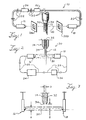
Fig. 1 generically illustrates an apparatus for verifying dispense of a fluid; -
Figs. 2 illustrates another embodiment of the apparatus shown inFig. 1 ; -
Figs. 3 is a schematic view of an apparatus for verifying dispense of a fluid showing relative positions of elements of the apparatus; -
Fig. 4 is a graph of an electronic signal generated by a receiver responsive to a signal sent by a source comprising an apparatus of verifying dispense; and -
Fig. 5 is a graph similar toFig. 4 showing an improper dispense. -
Fig. 1 illustrates oneembodiment 10 of an apparatus and a method for verifying dispense of afluid 12 from adispense nozzle 14. Dispense verification, as will become clear herein, refers to obtaining information about the status of a fluid dispense, detecting a major hanging drop of fluid, checking temporal duration of a dispense, etc. In the embodiments discussed herein, dispense verification utilizes an electromagnetic radiation intensity measurement, possibly coupled with a temporal measurement. - For the sake of clarity of understanding, the embodiments of the apparatus and method will be discussed with respect to their employment with an analytical instrument. For instance, the embodiments may be used with the instruments and methods disclosed in
U.S. Patent No.'s 5,006,309 ,5,089,424 ,5,120,199 ,5,185,264 ,5,198,368 and5,244,630 . Those patents are assigned to the assignee of the present case. However, it is to be recognized that each of the embodiments may have other employments without departing from the scope of the claims. - Multiple embodiments may be integrated along a processing path in a single instrument. While the
fluid 12 may be understood to be a reagent, other fluids are also possible. It may be desirable to locate an apparatus at every fluid addition location apt to cause a false result or inaccurate information being given to an instrument operator. Illustrating by example, in an analytical instrument, dispense verification apparatus may be located where particles, conjugates and/or probes are added to sample and where washes occur. - Returning to
Fig. 1 , theembodiment 10 comprises asource 16 of electromagnetic radiation and areceiver 18 operatively associated with thedispense nozzle 14. Thesource 16 and thereceiver 18 are disposed with respect to thedispense nozzle 14 such that flow offluid 12 from thenozzle 14 passes through apath 20 of electromagnetic radiation from thesource 16 to thereceiver 18. It is to be noted that thepath 20 passes through an ambient fluid, such as air. No lenses or filters are required. As will be discussed in further detail later, passage offluid 12 through thepath 20 allows for dispense verification. - The
source 16 and thereceiver 18 are predetermined such that thereceiver 18 generates a signal responsive to electromagnetic radiation sent from thesource 16. In an exemplary embodiment, thesource 16 may be a light emitting diode and the like. In a specific embodiment, thesource 16 is capable of emitting electromagnetic radiation of about 900nm (infrared). Thereceiver 18, in an exemplary embodiment, may be a phototransistor and the like. If thesource 16 were a diode emitting electromagnetic radiation at about 900nm, then thereceiver 18 would be chosen such that a peak sensitivity of thereceiver 18 would be in substantially the same range of the electromagnetic spectrum. If the infrared portion of the electromagnetic spectrum were used in theembodiment 10, then the amount of energy present in the photons travelling from thesource 16 to thereceiver 18 would be reduced. In a specific embodiment, thesource 16 is an SEP8706-002 and thereceiver 18 is an SDP8406-003, both being available from Honeywell, MICRO SWITCH, Optoelectronics Division of Richardson, Texas. - In the illustrated embodiments, the
source 16 and thereceiver 18 are electrically connected by awire 22 to other supporting electronics, such as acontroller 24 through apreamplifier 26, for instance. Thesource 16 is supplied with power at a substantially constant level. Thus, ifmultiple embodiments 10 were included in a specific instrument, then all embodiments may be compared against a common threshold, discussed later. - In the illustrated embodiment, the
preamplifier 26 presents a relatively high input impedance to match the impedance of thereceiver 18. Thepreamplifier 26 also presents a relatively low impedance to match the impedance of thecontroller 24. The relatively low impedance facilitates signal transmission alongconduit 22 towardcontroller 24. In an exemplary embodiment, thecontroller 24 comprises a processor, such as a Motorola (Schaumburg, Illinois) 68HC11F1 and the like, and a digital-to-analog converter, such as a 7228A, available from Analog Devices, Inc. of Norwood, Massachusetts, and the like. Ifmultiple apparatuses 10 were provided, then thecontroller 24 can include a multiplexer, such as one handling about six outputs and about 12 inputs. The outputs would drive, up to about 5mA, twosource 16/receiver 18 pairs connected electrically in series. Such a circuit can incorporate current feedback to provide a substantially linear response. In one embodiment, the multiplexer is predetermined to have a frequency response sufficient for about 98% setting in about 130 microseconds. In this manner, switching ofsource 16 drives and multiplexer input signals would be appropriately chosen such that the 12 inputs could be read, approximately, every 1.6 msec. - In a specific embodiment, the
preamplifier 26 drives twosource 16/receiver 18 pairs selectively with two predetermined electrical signals. For the sake of clarity, a first pair ofsource 16/receiver 18 is designated the "A" pair, while the other pair is designated the "B" pair. The A and B pairs are electrically connected in series with thepreamplifier 26. Thepreamplifier 26 drives the A and B pairs at a predetermined electrical signal appropriate for the A pair. The output of thereceiver 18 in the A pair is monitored. Then, thepreamplifier 26 drives the A and B pairs at a predetermined electrical signal for the B pair. The output of theB receiver 18 is monitored. If a plurality of A and B pairs were provided, then all of the pairs would be driven with the A electrical signal, the output of theA receivers 18 would be monitored sequentially, then all of the pairs would be driven with the B electrical signal and the output of all of theB receivers 18 would be monitored sequentially. - In this manner, the electrical signal driving all of the
sources 16 is not constant. The A electrical signal is applied to thesource 16 and the output of the associatedreceiver 18 is monitored after it settles. The B electrical signal is applied and the output of theB receiver 18 is monitored. This process can repeat at a rate of about 1250 times per second. Thus, eachreceiver 18 output is monitored about 625 times each second. Accordingly, during a dispense cycle, thereceiver 18 output can be monitored about 80 times while the output is below the threshold. This can result in an error tolerance of about one percent. - In still other embodiments, the
controller 24 may be provided with access, such as an RS232 port, to a computer for monitoring, controlling and trouble shooting theapparatus 10. The computer or other electronic element operatively associated with the access may provide a feedback signal to an operator indicative of the status of dispense offluid 12 from the dispensenozzle 14. - In the
embodiment 10 shown inFig. 1 , thesource 16 and thereceiver 18 are offset from the path offluid 12 flow from the dispensenozzle 14 by screens 28A and 28B, respectively. The screens 28A and 28B are constructed and located to reduce the chance thatfluid 12 flowing from the dispensenozzle 14 might reach thesource 16 or thereceiver 18. Iffluid 12 were to reach either thesource 16 or thereceiver 18, then theembodiment 10 may not operate as intended. The screens 28A and 28B may also be used if it were desired to avoid cleaning thesource 16 and/or thereceiver 18. In this embodiment, the screens 28A and 28B could be cleaned instead of thesource 16 andreceiver 18. - However, fluid 12 reaching the
source 16 and/or thereceiver 18 may not always be a concern. This may depend upon the characteristics of the fluid 12. Iffluid 12 reaching thesource 16 or thereceiver 18 were not a concern, then one or both of the screens 28A and 28B may be eliminated.Fig. 2 illustrates anembodiment 30 of an apparatus for verifying dispense offluid 12 from dispensenozzle 14 which does not comprise screens 28A and 28B. Theembodiment 30 is substantially similar to theembodiment 10 ofFig. 1 , hence the like reference numerals for similar structures. Bothembodiments - The relative locations of the
nozzle 14, thesource 16 and thereceiver 18 assist in intended operation of theembodiments Fig. 3 . The dimensions given in the following paragraphs are for the purposes of illustration only and are not intended to limit the scope of the claims. - In an exemplary embodiment, the dispense
nozzle 14 comprises abore 32 having a diameter D of about 0,762 mm (0.030 inches). Therefore, a stream offluid 12 leaving the dispensenozzle 14 has a diameter of about 0,762 mm (0.030 inches). - The
source 16, which illuminates relevant portions of thereceiver 18 with electromagnetic radiation, and thereceiver 18 are mutually exposed through an aperture having a diameter A of about 1,575 mm (0.062 inches). The apertures, in one embodiment, may be formed by a suitable technique, such as machining and the like, in a mounting bracket, formed from a suitable material such as aluminum and the like, operatively associated with thesource 16 and thereceiver 18. The apertures define dimensions of a latitudinal cross section of thepath 20 of electromagnetic radiation from thesource 16 to thereceiver 18. Thus, during dispense offluid 12 from thenozzle 14, the fluid 12 will encounter or block about half of the latitudinal cross section of thepath 20. - A longitudinal axis of the
path 20 is offset from a fluid-exitingend 34 of the dispensenozzle 14 by a specific, predetermined distance O, shown inFig. 3 . In an exemplary embodiment, the distance O is about 2,54 mm (0.10 inches). The distance O is chosen so that theembodiments fluid 12 depending from theend 34 of the dispensenozzle 14. Put in another way, the distance O is chosen such that theembodiments fluid 12 and avoid a minor drop offluid 12 depending or hanging from theend 34 of thenozzle 14. - A major drop of
fluid 12 contains a volume offluid 12 sufficient to significantly adversely affect dispense of an intended volume offluid 12 from thenozzle 14, whereas a minor drop offluid 12 does not have sufficient volume offluid 12 to significantly adversely affect dispense of an intended volume offluid 12. Thus, it can be appreciated that, by avoiding detection of minor hanging drops offluid 12, the likelihood of sensing a dispense incorrectly can be reduced. However, detecting major hanging drops is desirable because a major hanging drop can significantly affect dispense offluid 12 from the dispensenozzle 14. If the dispense offluid 12 were significantly affected, then it is possible that the instrument associated with the dispensenozzle 14 could give the instrument operator incorrect information about a sample being tested. - Detection of a major hanging drop is also dependent upon a threshold applied to a signal generated by the
receiver 18. The threshold is a predetermined percentage of electromagnetic signal (i.e. electromagnetic intensity) sent from thesource 16 and received by thereceiver 18. The threshold may be considered to represent a portion of the electromagnetic signal sent from thesource 16 and blocked from reaching thereceiver 18 byfluid 12 depending or dispensed from the dispensenozzle 14. The value of the threshold is predetermined such that theembodiments embodiments receiver 18 with the threshold, thereby indicative of fluid dispense status and/or hanging drops, to the operator. - For example, if the threshold were set at about 90% of the
source 16 intensity, then theembodiments receiver 18 was illuminated by thesource 16 at a level of less than about 90% of the level of illumination of thereceiver 18 by thesource 16 when no fluid 12 is present (i.e. a quiescent state). Thus, theembodiments receiver 18 were to fall by about 10% from its quiescent state. - If the
receiver 18 threshold were set to detect an about 10% drop in electromagnetic intensity sent by thesource 16, then theembodiments fluid 12, having a fluid volume as small as about 10 µl, for example, depending from theend 34 of thenozzle 14. In this manner, the effects of things which cause a dispense offluid 12 from thenozzle 14 to decrease or trail off relatively slowly at the end of a dispense cycle, rather than the dispense cycle ending abruptly, can be detected. - With the construction of the
embodiments embodiment embodiments embodiments - It is assumed that no fluid 12 has left the dispense
nozzle 14 so that no fluid 12 has passed through thenozzle 14 to form a hanging drop. Thesource 16 is energized to produce an electromagnetic signal of predetermined characteristics. The electromagnetic signal travels from thesource 16 along thepath 20 to thereceiver 18. Thesource 16 generates this electromagnetic signal substantially continuously during operation of theembodiments embodiments source 16 would generate the electromagnetic signal throughout substantially the entire duration of analytical instrument operation. At this point, thereceiver 18 is at the quiescent state. The electromagnetic signal received by thereceiver 18 at this time is defined as the quiescent or reference signal. - The substantially continuous operation of the
source 16 allows for substantially fail-safe operation of the embodiments. Specifically, as will become clear herein, the electromagnetic signal travels from thesource 16 to thereceiver 18 substantially continuously so that any deviation, as determined by thecontroller 24, in transmitted signal intensity, received by thereceiver 18 can be used to provide feedback indicative offluid 12 dispense from thenozzle 14 to the operator. - The intensity of the electromagnetic signal transmitted by the
source 16 and received thereceiver 18 is used to determine the threshold discussed earlier. If there weremultiple embodiments fluid 12 from thenozzle 14 during an intended fluid dispense cycle will pass through about half of thepath 20 of electromagnetic radiation from thesource 16 to thedetector 18, the threshold may be selected to be about 75% of the quiescent state signal. - Illustrating further by example, in one embodiment, the
source 16 driving signal is adjusted prior to dispense offluid 12 from the dispensenozzle 14. Thesource 16 driving signal is adjusted so that the quiescent signal is at a desired, predetermined level above the threshold. Thesource 16 driving signal can be adjusted within the range of a maximum and aminimum source 16 driving signal associated with therelevant source 16. If it were not possible to adjust thesource 16 driving signal such that the quiescent signal is above the threshold by the desired amount, then an error message may be reported to an operator. Thus, functionality of the associatedsource 16/receiver 18 pair is verified. - According to the invention a major hanging drop is detected. Therefore, it may be desirable to set the threshold substantially within the range of about 80% to about 90% of the quiescent signal. The exact value of the threshold may depend on a number of factors, such as physical dimensions of the
embodiments controller 24. Thecontroller 24 may update the threshold as necessary, thereby possibly allowing for obstructions, such as dust, other than fluid 12 in thepath 20. These obstructions may accumulate over time, thereby making updating of the threshold desirable. - With the threshold set, fluid 12 dispense cycles can begin. As
fluid 12 exits the dispensenozzle 14, the fluid 12 passes through thepath 20 and correspondingly reduces the intensity of the electromagnetic signal reaching thereceiver 18. The electromagnetic intensity received by thereceiver 18 is monitored by thecontroller 24. - In some embodiments, the
controller 24 may contain a timer to monitor duration of the reduction in received electromagnetic intensity. In these embodiments, thecontroller 24 monitors the time interval during which the electromagnetic intensity received by thereceiver 18 is reduced below the predetermined threshold. The end of the dispense cycle is determined by the intensity received by thereceiver 18 returning to a value greater than the threshold. The time between the moment the received intensity falls below the threshold and the moment the received intensity rises above the threshold is an actual temporal duration of the dispense cycle. This actual temporal duration is compared to a predetermined, expected temporal duration of the dispense cycle, which may be determined empirically. The expected temporal duration may depend onfluid 12 pump tolerances, conduit length from pump to theend 34 of the dispensenozzle 14, etc. In an exemplary embodiment, an expected temporal duration may be about 124 msec. to about 144 msec. If the two temporal durations were substantially the same, then thecontroller 24 can cause feedback indicative of a proper dispense to be sent to the operator. If the actual and expected durations were not substantially the same, then thecontroller 24 can cause feedback indicative of an improper dispense to be sent to the operator. - In an exemplary embodiment, an electronic signal generated by the
receiver 18 responsive to the electromagnetic signal sent by thesource 16 during a proper dispense is shown inFig. 4 . In this example, it is assumed that the threshold is set at about 90% of the quiescent signal Q and the expected temporal duration for a proper dispense is substantially within the range of 124 and 144 msec. - As the graph shows, the dispense cycle begins, labelled "X" in
Fig. 4 , andfluid 12 flowing from the dispensenozzle 14 blocks a portion of thepath 20. The fluid 12 reduces the intensity of the electromagnetic signal received by thereceiver 18. The received intensity is reduced sufficiently such that it falls below the predetermined threshold value. This reduction in received intensity lasts for about 138 msec (actual temporal duration). When the dispense cycle ends, indicated by "Y" inFig. 4 , the received intensity increases, rises above the threshold value and approaches the quiescent signal Q. Thecontroller 24 compares the actual and expected temporal durations. Because the two durations are substantially identical, this dispense is a proper dispense. If desired, thecontroller 24 can cause a relevant feedback signal to be sent to the operator. - Signal transmission from the
source 16 to thereceiver 18 continues. If desired, it is possible to reset the threshold. This may be desirable if, for reasons other than a hanging drop, such as dust and the like, the received intensity were not to return to the quiescent signal. Theembodiments - Improper dispenses can have a number of causes. One of the causes may be a gas, i.e. air bubble and the like, in the fluid 12 path from a fluid 12 stock container to the
end 34 of the dispensenozzle 14. Many things may cause gas to be present in the fluid path. For instance, the fluid 12 system may have been improperly "primed", the fluid 12 stock container may be almost empty, connections in the fluid 12 system may leak, fluid 12 may be restricted, there may be effects due to siphoning, etc. - If a gas were in the fluid line, then the actual temporal duration may be shortened. This can occur without changing substantially the volume of
fluid 12 dispensed from the dispensenozzle 14. The gas in the line may be compressed during initial activation of apump forcing fluid 12 through the line supplying the dispensenozzle 14, thereby possibly causing a delay in beginning the dispense. In addition, at the end of the dispense cycle, the velocity of the fluid 12 leaving theend 34 of the dispensenozzle 14 may be greater than the fluid velocity generated by the pump. The increasedfluid 12 velocity can cause the desired volume offluid 12 to leave the dispensenozzle 14 before the expiration of the expected temporal duration. Also, the increasedfluid 12 velocity can cause fluid 12 to splash into unintended places. - Build-up of
fluid 12 residue, which may be caused byfluid 12 evaporating from theend 34 of thenozzle 14, may direct fluid 12 from theend 34 of the dispensenozzle 14 in an unintended direction. Misdirection offluid 12 from theend 34 of the dispensenozzle 14 during a dispense cycle may result in an improper dispense which is also detectable by theembodiment 10. Thus, theembodiment 10 can also verify thatfluid 12 was dispensed from the dispensenozzle 14 in an intended path or direction. - Another cause of improper dispenses may be a drop of
fluid 12 depending or hanging from theend 34 of the dispense nozzle. The hanging drop may be formed by fluid pressure being relieved through the dispensenozzle 14. This may be caused by a "kink" or other restriction in the fluidline supplying fluid 12 to the dispensenozzle 14. A hanging drop may become a restriction tofluid 12 leaving thenozzle 14 through theend 34. Depending upon the composition of the fluid 12 and the time of duration of the hanging drop, it is possible that the fluid 12 comprising the drop may dry on the dispensenozzle 14. Also, it is possible thatfluid 12 hanging from theend 34 of thenozzle 14 in the form of a drop may fall off of theend 34 of thenozzle 14 at an unadvantageous time. The falling drop may cause erroneous information to be given to the operator. Thus, it is recommended that all data associated with tests involving an improper dispense be discarded. - To further clarify, in an exemplary embodiment, an electronic signal generated by the
receiver 18 responsive to the electromagnetic signal sent by thesource 16 during an improper dispense is shown inFig. 5 . For the sake of clarity, the threshold and the expected temporal durations are assumed to be the same as described above. During the time period illustrated, it is not intended to dispense any fluid 12 from thenozzle 14. The improper dispense, in this example, is the result of a major hanging drop. The major hanging drop may have been caused byfluid 12 slowing leaking from theend 34 of the dispensenozzle 14. This may be indicative of a defect in thenozzle 14 or in theconduit supplying fluid 12 to thenozzle 14. - The received signal, at point A in
Fig. 5 , is at about the quiescent signal. As time progresses, more fluid 12 leaks from theend 34 of thenozzle 14. A drop begins to form at theend 34. The drop offluid 12 directs stray light back into thepath 20 of electromagnetic radiation from thesource 16 to thereceiver 18. The direction of stray light into thepath 20 causes the received intensity to increase, as shown at B. - The received intensity increases until a portion of the drop of
fluid 12 depending from theend 34 of thenozzle 14 begins to obstruct a portion of thepath 20 between thesource 16 and thereceiver 18. At this point C, the received intensity of electromagnetic intensity begins to decrease. The received intensity decreases until the drop offluid 12 is sufficient to substantially focus or direct electromagnetic radiation from thesource 16 onto thereceiver 18. As shown, the received intensity increases due to the redirection effected by the drop offluid 12 hanging from theend 34 of the dispensenozzle 14. - The size of the hanging drop continues to grow as more and more fluid 12 leaks from the dispense
nozzle 14. The size of the drop increases until forces of the system, e.g. gravity, surface tension, adhesion, etc., are insufficient to maintain the drop offluid 12 on theend 34 of the dispensenozzle 14. At this point, labelled E, the drop falls off of theend 34 of the dispensenozzle 14. Because there is substantially no fluid 12 depending from theend 34 of thenozzle 14, thepath 20 is substantially unobstructed. The received intensity increases, labelled F, toward the quiescent signal. Becausefluid 12 continues to leak from theend 34 of thenozzle 14, the above-described behavior repeats. - Given the above examples, it is evident how any conditions relevant to a fluid 12 dispense from the dispense
nozzle 14 can be monitored by theembodiments end 34 of the dispensenozzle 14 and the longitudinal mid line of thepath 20 may be determined to allow detection of minor hanging drops. The threshold may be predetermined to allow detection of air bubbles, clots, inhomogeneities, etc. in the dispensedfluid 12 as it flows from theend 34 of the dispensenozzle 14. - Where technical features mentioned in any claim are followed by reference signs, those reference signs have been included just for the sole purpose of increasing intelligibility of the claims and accordingly, such reference signs do not have any limiting effect on the scope of each element identified by way of example by such reference signs.
Claims (11)
- A method for verifying dispense of a fluid from a dispense nozzle (14), the method comprising the steps of:(a) providing a source (16) of electromagnetic radiation and a receiver (18) of the electromagnetic radiation from the source (16) of electromagnetic radiation, such that the flow of a fluid (12) from the nozzle (14) passes through a path (20) of electromagnetic radiation from the source (16) to the receiver (18);(b) energizing the source (16) such that the source (16) produces electromagnetic radiation;(c) illuminating the receiver (18) with the electromagnetic radiation;(d) generating with the receiver (18) a first signal;(e) setting a threshold based on the first signal, the threshold being a predetermined percentage of the first signal and such that a minor drop of fluid (12), having a volume not sufficient to significantly adversely affect dispense of an intended volume of fluid (12), depending from the dispense nozzle (14) is not detected;(f) dispensing fluid (12) from the dispense nozzle (14);(g) obstructing the electromagnetic signal between the source (16) and the receiver (18) with the fluid (12) dispensed from the dispense nozzle (14);(h) generating with the receiver (18) a second signal;(i) comparing the threshold and the second signal substantially continuously to indicate start of a dispense of fluid (12) from the dispense nozzle (14);(j) generating with the receiver (18) a third signal;(k) comparing the third signal and the threshold to indicate finish of a dispense of fluid (12) from the dispense nozzle (14);(l) determining a first time period between generation of the second signal and generation of the third signal;(m) determining a second time period of an expected temporal duration between start and finish of the dispense of fluid (12) from the dispense nozzle (14); and(n) comparing the first time period and the second time period to verify the dispense of fluid (12) from the dispense nozzle (14).
- A method as defined in claim 1 further comprising the step of:(o) locating the source (16) and the receiver (18) with respect to the dispense nozzle (14) such that a major drop of fluid (12), having a volume sufficient to significantly adversely affect dispense of an intended volume of fluid (12), depending from the dispense nozzle (14) obstructs the electromagnetic signal between the source (16) and the receiver (18).
- A method as defined in claim 1 further comprising the step of:(o) setting the threshold such that a major drop of fluid (12), having a volume sufficient to significantly adversely effect dispense of an intended volume of fluid (12), depending from the dispense nozzle (14) is detected.
- A method as defined in claim 1 further comprising the steps of:(o) generating a feedback signal indicative of a result of step (n); and(p) providing the feedback signal to an operator.
- A method as defined in claim 1 further comprising the steps of:(o) defining the path (20) of electromagnetic radiation having a longitudinal axis between the source (16) and the receiver (18); and(p) offsetting the longitudinal axis of the path (20) of electromagnetic radiation between the source (16) and the receiver (18) from a fluid exiting end (34) of the dispense nozzle (14) by a distance of about 2,54 mm (0.1 inches),
- A method as defined in claim 1 further comprising the step of:(o) locating the source (16) and the receiver (18) with respect to the dispense nozzle (14) such that a minor drop of fluid (12), having a volume not sufficient to significantly adversely affect dispense of an intended volume of fluid (12), depending from the dispense nozzle (14) does not significantly obstruct the electromagnetic signal between the source (16) and the receiver (18).
- A method as defined in claim 1 further comprising the step of:(o) inhibiting fluid (12) dispensed from the dispense nozzle (14) from reaching at least one of the source (16) and the receiver (18).
- A method as defined in one or more of claims 1-7 further comprising the step of:(o) updating the threshold.
- A method as defined in claim 1 wherein the threshold is sufficient:for detection of a major drop of fluid (12), having a volume sufficient to significantly adversely effect dispense of an intended volume of fluid (12), depending from the dispense nozzle (14), and further comprising the step of:comparing the second signal with the threshold to verify a dispense of the fluid (12) from the dispense nozzle (14).
- A method as defined in claim 9 further comprising the steps of:(o) defining the path (20) of electromagnetic radiation having a longitudinal axis between the source (16) and the receiver (18); and(p) offsetting the longitudinal axis of the path (20) of electromagnetic radiation between the source (16) and the receiver (18) from a fluid exiting end (34) of the dispense nozzle (14) by a distance of about 2,54 mm (0.1 inches).
- A method as defined in claim 10 further comprising the step of:(p) inhibiting fluid (12) dispensed from the dispense nozzle (14) from reaching at least one of the source (16) and the receiver (18).
Applications Claiming Priority (3)
| Application Number | Priority Date | Filing Date | Title |
|---|---|---|---|
| US332307 | 1994-10-31 | ||
| US08/332,307 US5559339A (en) | 1994-10-31 | 1994-10-31 | Method and apparatus for verifying dispense of a fluid from a dispense nozzle |
| EP95939513A EP0789845B1 (en) | 1994-10-31 | 1995-10-06 | Method and apparatus for dispense verification |
Related Parent Applications (2)
| Application Number | Title | Priority Date | Filing Date |
|---|---|---|---|
| EP95939513A Division EP0789845B1 (en) | 1994-10-31 | 1995-10-06 | Method and apparatus for dispense verification |
| EP95939513A Division-Into EP0789845B1 (en) | 1994-10-31 | 1995-10-06 | Method and apparatus for dispense verification |
Publications (3)
| Publication Number | Publication Date |
|---|---|
| EP1202066A2 EP1202066A2 (en) | 2002-05-02 |
| EP1202066A3 EP1202066A3 (en) | 2002-07-31 |
| EP1202066B1 true EP1202066B1 (en) | 2008-12-10 |
Family
ID=23297658
Family Applications (2)
| Application Number | Title | Priority Date | Filing Date |
|---|---|---|---|
| EP02000782A Expired - Lifetime EP1202066B1 (en) | 1994-10-31 | 1995-10-06 | Method for dispense verification |
| EP95939513A Expired - Lifetime EP0789845B1 (en) | 1994-10-31 | 1995-10-06 | Method and apparatus for dispense verification |
Family Applications After (1)
| Application Number | Title | Priority Date | Filing Date |
|---|---|---|---|
| EP95939513A Expired - Lifetime EP0789845B1 (en) | 1994-10-31 | 1995-10-06 | Method and apparatus for dispense verification |
Country Status (7)
| Country | Link |
|---|---|
| US (1) | US5559339A (en) |
| EP (2) | EP1202066B1 (en) |
| JP (1) | JP3213325B2 (en) |
| AT (2) | ATE231974T1 (en) |
| DE (2) | DE69535896D1 (en) |
| ES (2) | ES2316493T3 (en) |
| WO (1) | WO1996013726A1 (en) |
Families Citing this family (51)
| Publication number | Priority date | Publication date | Assignee | Title |
|---|---|---|---|---|
| US6235242B1 (en) * | 1997-09-25 | 2001-05-22 | Robert A. Small | Sample size characterization technique and apparatus for liquid analysis |
| ES2253797T3 (en) * | 1998-08-17 | 2006-06-01 | F. Hoffmann-La Roche Ag | DEVICE FOR THE CONTROL OF PROCESSES OF PIPETEADO. |
| US6612676B1 (en) | 1998-11-17 | 2003-09-02 | Pitney Bowes Inc. | Apparatus and method for real-time measurement of digital print quality |
| US6350006B1 (en) * | 1998-11-17 | 2002-02-26 | Pitney Bowes Inc. | Optical ink drop detection apparatus and method for monitoring operation of an ink jet printhead |
| US6604807B1 (en) * | 1999-02-18 | 2003-08-12 | Hewlett-Packard Company | Method and apparatus for detecting anomalous nozzles in an ink jet printer device |
| ATE328670T1 (en) | 1999-11-11 | 2006-06-15 | Trinity College Dublin | DEVICE AND METHOD FOR ADMINISTRATION OF DROPS |
| US6347976B1 (en) | 1999-11-30 | 2002-02-19 | The Boeing Company | Coating removal system having a solid particle nozzle with a detector for detecting particle flow and associated method |
| AU2005211566B2 (en) * | 2000-02-29 | 2007-01-04 | Gen-Probe Incorporated | Fluid dispense and fluid surface verification system and method |
| JP4717312B2 (en) | 2000-02-29 | 2011-07-06 | ジェン−プローブ・インコーポレイテッド | Fluid transfer probe |
| GB0012184D0 (en) * | 2000-05-22 | 2000-07-12 | Ibm | Suface analysis |
| US6617079B1 (en) * | 2000-06-19 | 2003-09-09 | Mykrolis Corporation | Process and system for determining acceptibility of a fluid dispense |
| US20020168297A1 (en) * | 2001-05-11 | 2002-11-14 | Igor Shvets | Method and device for dispensing of droplets |
| US20060048841A1 (en) * | 2002-07-26 | 2006-03-09 | Gfi Innovations, Llc | Methodology and apparatus for storing and dispensing liquid components to create custom formulations |
| US7198073B2 (en) * | 2002-07-26 | 2007-04-03 | Gfi, Innovations | Methodology and apparatus for storing and dispensing liquid components to create custom formulations |
| US7114368B2 (en) * | 2003-04-08 | 2006-10-03 | Abbott Laboratories | Apparatus and method for verifying the volume of liquid dispensed by a liquid-dispensing mechanism |
| DE102005010847B4 (en) * | 2005-03-07 | 2007-08-02 | Rea Elektronik Gmbh | Device for measuring an exiting liquid |
| US7403125B2 (en) * | 2005-05-06 | 2008-07-22 | Accuri Cytometers, Inc. | Flow cytometry system with bubble detection |
| JP4593404B2 (en) | 2005-08-29 | 2010-12-08 | シスメックス株式会社 | Liquid sample suction monitoring method and apparatus, and liquid sample analyzer |
| US8017402B2 (en) | 2006-03-08 | 2011-09-13 | Accuri Cytometers, Inc. | Fluidic system for a flow cytometer |
| US8303894B2 (en) | 2005-10-13 | 2012-11-06 | Accuri Cytometers, Inc. | Detection and fluidic system of a flow cytometer |
| US8283177B2 (en) * | 2006-03-08 | 2012-10-09 | Accuri Cytometers, Inc. | Fluidic system with washing capabilities for a flow cytometer |
| US7780916B2 (en) * | 2006-03-08 | 2010-08-24 | Accuri Cytometers, Inc. | Flow cytometer system with unclogging feature |
| JP4906416B2 (en) | 2006-07-11 | 2012-03-28 | 日本碍子株式会社 | Object passage detection device |
| US8715573B2 (en) | 2006-10-13 | 2014-05-06 | Accuri Cytometers, Inc. | Fluidic system for a flow cytometer with temporal processing |
| WO2008058217A2 (en) | 2006-11-07 | 2008-05-15 | Accuri Instruments Inc. | Flow cell for a flow cytometer system |
| EP1946843A1 (en) | 2006-12-21 | 2008-07-23 | Allegro Research Limited | Apparatus and method for monitoring and measurement of droplets |
| US8432541B2 (en) * | 2007-12-17 | 2013-04-30 | Accuri Cytometers, Inc. | Optical system for a flow cytometer with an interrogation zone |
| DE102008016513B4 (en) * | 2008-03-31 | 2012-12-20 | Bartels Mikrotechnik Gmbh | Device and method for exact dosing of liquids |
| US7804599B2 (en) * | 2008-07-24 | 2010-09-28 | MGM Instruments, Inc. | Fluid volume verification system |
| US8507279B2 (en) * | 2009-06-02 | 2013-08-13 | Accuri Cytometers, Inc. | System and method of verification of a prepared sample for a flow cytometer |
| US20110061471A1 (en) * | 2009-06-02 | 2011-03-17 | Rich Collin A | System and method of verification of a sample for a flow cytometer |
| US9551600B2 (en) | 2010-06-14 | 2017-01-24 | Accuri Cytometers, Inc. | System and method for creating a flow cytometer network |
| WO2012061155A2 (en) | 2010-10-25 | 2012-05-10 | Accuri Cytometers, Inc. | Systems and user interface for collecting a data set in a flow cytometer |
| US9010580B2 (en) * | 2010-10-29 | 2015-04-21 | Whirlpool Corporation | Stream detection and/or characterization for beverage dispensing in a refrigerator |
| US20130074982A1 (en) * | 2011-09-28 | 2013-03-28 | Gfi Innovations, Inc. | Methodology and Apparatus for Storing and Dispensing Liquid Components to Create Custom Formulations |
| US10504758B2 (en) * | 2014-02-14 | 2019-12-10 | Taiwan Semiconductor Manufacturing Company Ltd. | Nozzle having real time inspection functions |
| WO2017151516A1 (en) | 2016-02-29 | 2017-09-08 | Ventana Medical Systems, Inc. | System and method for dispense characterization |
| US10072962B2 (en) * | 2016-07-05 | 2018-09-11 | Ecolab Usa Inc. | Liquid out-of-product alarm system and method |
| DE102016114607B4 (en) * | 2016-08-05 | 2025-03-20 | Infineon Technologies Ag | Liquid delivery system, device and method |
| EP3501335B1 (en) | 2017-12-20 | 2020-06-17 | The Gillette Company LLC | Oral care implement |
| EP3524093A1 (en) | 2018-02-09 | 2019-08-14 | The Gillette Company LLC | A method for manufacturing an oral care implement |
| PL3524091T3 (en) | 2018-02-09 | 2025-06-23 | The Gillette Company Llc | Manual oral care implement |
| US11659922B2 (en) | 2018-09-03 | 2023-05-30 | The Gillette Company, LLC. | Head for an oral-care implement and a kit comprising such head |
| PL3616561T3 (en) | 2018-09-03 | 2022-11-21 | The Gillette Company Llc | Head for an oral care implement and a kit comprising such head |
| EP3714732B1 (en) | 2019-03-29 | 2024-11-20 | The Gillette Company LLC | Head for an oral care implement and oral care implement |
| EP3818904B1 (en) | 2019-11-06 | 2024-12-18 | The Gillette Company LLC | Handle for an electrically operated personal care implement |
| EP3995038B1 (en) | 2020-11-06 | 2025-05-14 | The Gillette Company LLC | Handle for a personal care implement and personal care implement |
| PL3995040T3 (en) | 2020-11-06 | 2025-06-16 | The Gillette Company Llc | Handle for a personal care implement and personal care implement |
| PL3995042T3 (en) | 2020-11-06 | 2025-07-21 | The Gillette Company Llc | Handle for a personal care implement and personal care implement |
| ES2967286T3 (en) | 2020-11-06 | 2024-04-29 | Gillette Co Llc | Handle for a personal care utensil and personal care utensil |
| PL3995037T3 (en) | 2020-11-06 | 2025-06-02 | The Gillette Company Llc | Handle for a personal care implement and personal care implement |
Family Cites Families (37)
| Publication number | Priority date | Publication date | Assignee | Title |
|---|---|---|---|---|
| BE568988A (en) * | 1957-05-23 | |||
| US3143393A (en) * | 1959-06-18 | 1964-08-04 | Luc Donald De Seguin Des Hons | Apparatus for automatically performing chemical operations and similar or related operations |
| US3600953A (en) * | 1969-07-25 | 1971-08-24 | Technicon Corp | Method and apparatus for the introduction of auxiliary separating fluid in fluid sample analyses means |
| US3759667A (en) * | 1971-10-22 | 1973-09-18 | Damon Corp | Apparatus for aspirating precise volumes of fluid sample |
| DE2219862A1 (en) * | 1972-04-22 | 1973-10-31 | Hans Dr Haug | METHOD AND DEVICE FOR DISTRIBUTING LIQUID SAMPLES, IN PARTICULAR SERUM SAMPLES IN THE FIELD OF CLINICAL CHEMISTRY |
| US3874850A (en) * | 1972-07-24 | 1975-04-01 | Radiometer As | Blood analyzing method and apparatus |
| US3994423A (en) * | 1973-06-28 | 1976-11-30 | American Hospital Supply Corporation | Drop dispensing apparatus for laboratory reagents |
| US3929413A (en) * | 1974-03-04 | 1975-12-30 | Anatronics Corp | Fluid transport and metering system |
| US4253846A (en) * | 1979-11-21 | 1981-03-03 | Technicon Instruments Corporation | Method and apparatus for automated analysis of fluid samples |
| US4312341A (en) * | 1979-12-13 | 1982-01-26 | Baxter Travenol Laboratories, Inc. | Bubble detector |
| US4344429A (en) * | 1979-12-13 | 1982-08-17 | Baxter Travenol Laboratories, Inc. | Bubble detector with feedback circuit for improved sensitivity |
| US4372150A (en) * | 1980-06-05 | 1983-02-08 | Beckman Instruments, Inc. | Flow monitoring method and apparatus |
| JPS5811859A (en) * | 1981-07-16 | 1983-01-22 | Olympus Optical Co Ltd | Dispensation detector |
| US4420566A (en) * | 1982-06-10 | 1983-12-13 | Eastman Kodak Company | Method and apparatus for detecting sample fluid on an analysis slide |
| JPS595933A (en) * | 1982-07-02 | 1984-01-12 | Hitachi Ltd | Flow analysis of liquid sample |
| JPS5919858A (en) * | 1982-07-26 | 1984-02-01 | Sanuki Kogyo Kk | Automatic processing device for analysis |
| US4526754A (en) * | 1982-07-30 | 1985-07-02 | Technicon Instruments Corporation | Sample transport system |
| US4853336A (en) * | 1982-11-15 | 1989-08-01 | Technicon Instruments Corporation | Single channel continuous flow system |
| US4517302A (en) * | 1982-11-15 | 1985-05-14 | Technicon Instruments Corporation | Continuous flow metering apparatus |
| DE3344387A1 (en) * | 1983-12-08 | 1985-06-20 | Hoechst Ag, 6230 Frankfurt | PHOTOMETER HEAD FOR SMALL MEASURING VOLUME |
| JPS61231461A (en) * | 1985-04-05 | 1986-10-15 | Fuji Photo Film Co Ltd | Apparatus for dripping specimen |
| DE3683573D1 (en) * | 1985-06-26 | 1992-03-05 | Japan Tectron Instr Corp | AUTOMATIC ANALYZER. |
| US4640821A (en) * | 1985-07-16 | 1987-02-03 | Fisher Scientific Company | Analysis apparatus |
| US4691580A (en) * | 1986-01-08 | 1987-09-08 | Egil Fosslien | Fluid sampling apparatus |
| US4703314A (en) * | 1986-02-27 | 1987-10-27 | Fisher Scientific Group, Inc. | Empty container detector with drop sensor |
| US4752690A (en) * | 1986-08-11 | 1988-06-21 | Coulter Electronics, Inc. | Method and apparatus for detecting incongruities, such as air bubbles, in fluid material |
| US4935346A (en) * | 1986-08-13 | 1990-06-19 | Lifescan, Inc. | Minimum procedure system for the determination of analytes |
| DD255002A1 (en) * | 1986-12-17 | 1988-03-16 | Medizin Labortechnik Veb K | METHOD AND DEVICE FOR GENERATING A SAMPLE CURRENT FOR CONTINUOUS ANALYSIS AUTOMATES |
| US4861553A (en) * | 1987-06-11 | 1989-08-29 | Technicon Instruments Corporation | Automatic sampling system |
| US4896545A (en) * | 1988-04-22 | 1990-01-30 | Dynatech Precision Sampling Corporation | Automatic fluid injector |
| US5067092A (en) * | 1990-01-24 | 1991-11-19 | Eastman Kodak Company | Prespot detection method and apparatus in an analyzer |
| US5094961A (en) * | 1990-12-13 | 1992-03-10 | Coulter Corporation | Aspiration method for hematology analyzing apparatus |
| JPH05223830A (en) * | 1991-04-04 | 1993-09-03 | Olympus Optical Co Ltd | Method and device for detecting dispensated quantity |
| JP2539126Y2 (en) * | 1991-08-26 | 1997-06-25 | 東亜医用電子株式会社 | Sample suction monitoring device with automatic adjustment function |
| JP3230277B2 (en) * | 1992-05-15 | 2001-11-19 | 東ソー株式会社 | Liquid discharge monitoring method and apparatus therefor |
| US5352887A (en) * | 1992-08-28 | 1994-10-04 | Motorola, Inc. | Circuit for detecting a droplet in motion and method therefor |
| US5434430A (en) * | 1993-04-30 | 1995-07-18 | Hewlett-Packard Company | Drop size detect circuit |
-
1994
- 1994-10-31 US US08/332,307 patent/US5559339A/en not_active Expired - Lifetime
-
1995
- 1995-10-06 WO PCT/US1995/013091 patent/WO1996013726A1/en not_active Ceased
- 1995-10-06 AT AT95939513T patent/ATE231974T1/en not_active IP Right Cessation
- 1995-10-06 JP JP51461196A patent/JP3213325B2/en not_active Expired - Fee Related
- 1995-10-06 DE DE69535896T patent/DE69535896D1/en not_active Expired - Lifetime
- 1995-10-06 DE DE69529531T patent/DE69529531T2/en not_active Expired - Lifetime
- 1995-10-06 EP EP02000782A patent/EP1202066B1/en not_active Expired - Lifetime
- 1995-10-06 EP EP95939513A patent/EP0789845B1/en not_active Expired - Lifetime
- 1995-10-06 ES ES02000782T patent/ES2316493T3/en not_active Expired - Lifetime
- 1995-10-06 ES ES95939513T patent/ES2191718T3/en not_active Expired - Lifetime
- 1995-10-06 AT AT02000782T patent/ATE417277T1/en not_active IP Right Cessation
Also Published As
| Publication number | Publication date |
|---|---|
| JPH10506998A (en) | 1998-07-07 |
| JP3213325B2 (en) | 2001-10-02 |
| WO1996013726A1 (en) | 1996-05-09 |
| DE69535896D1 (en) | 2009-01-22 |
| DE69529531T2 (en) | 2003-11-20 |
| ATE417277T1 (en) | 2008-12-15 |
| EP1202066A3 (en) | 2002-07-31 |
| DE69529531D1 (en) | 2003-03-06 |
| ES2316493T3 (en) | 2009-04-16 |
| US5559339A (en) | 1996-09-24 |
| EP1202066A2 (en) | 2002-05-02 |
| EP0789845B1 (en) | 2003-01-29 |
| ATE231974T1 (en) | 2003-02-15 |
| EP0789845A1 (en) | 1997-08-20 |
| ES2191718T3 (en) | 2003-09-16 |
Similar Documents
| Publication | Publication Date | Title |
|---|---|---|
| EP0789845B1 (en) | Method and apparatus for dispense verification | |
| CN103026241B (en) | Automatic analysis device | |
| EP1059535B1 (en) | Method of verifying aspirated volume in automatic diagnostic system | |
| US4318483A (en) | Automatic relative droplet charging time delay system for an electrostatic particle sorting system using a relatively moveable stream surface sensing system | |
| EP1036335B1 (en) | Method of verifying aspirated volume in automatic diagnostic system | |
| US6203759B1 (en) | Microvolume liquid handling system | |
| EP0753750B1 (en) | Method and apparatus for aspirating and dispensing sample fluids | |
| WO2001002836A1 (en) | Apparatus and method for verifying drop delay in a flow cytometer | |
| US6370942B1 (en) | Method for verifying the integrity of a fluid transfer | |
| US5540081A (en) | Pipetting apparatus with clot detection | |
| EP1316802B1 (en) | An analyzing method of a blood coagulation reaction | |
| US4317520A (en) | Servo system to control the spatial position of droplet formation of a fluid jet in a cell sorting apparatus | |
| US6641545B1 (en) | Biological sampling method | |
| JPH0217448A (en) | Air type detection system | |
| EP0075440B1 (en) | Reagent mixing system and method | |
| EP0042337B1 (en) | Method and apparatus for metering biological fluids | |
| CA2202649C (en) | Method and apparatus for dispense verification | |
| JPH05223830A (en) | Method and device for detecting dispensated quantity | |
| JP2013044692A (en) | Dispensation mechanism and automatic analyzer using the same | |
| US5763795A (en) | Sampling apparatus | |
| EP0394041A2 (en) | Capillary flow device and reading instrument | |
| JPH052025A (en) | Dispensation amount detecting apparatus and method | |
| JPH11118702A (en) | Sample-analyzing apparatus with cleaning control function | |
| JPH11142415A (en) | Liquid dispensing device |
Legal Events
| Date | Code | Title | Description |
|---|---|---|---|
| PUAI | Public reference made under article 153(3) epc to a published international application that has entered the european phase |
Free format text: ORIGINAL CODE: 0009012 |
|
| AC | Divisional application: reference to earlier application |
Ref document number: 789845 Country of ref document: EP |
|
| AK | Designated contracting states |
Kind code of ref document: A2 Designated state(s): AT BE CH DE ES FR GB IT LI NL |
|
| PUAL | Search report despatched |
Free format text: ORIGINAL CODE: 0009013 |
|
| AK | Designated contracting states |
Kind code of ref document: A3 Designated state(s): AT BE CH DE ES FR GB IT LI NL |
|
| 17P | Request for examination filed |
Effective date: 20030108 |
|
| AKX | Designation fees paid |
Designated state(s): AT BE CH DE ES FR GB IT LI NL |
|
| 17Q | First examination report despatched |
Effective date: 20060823 |
|
| GRAP | Despatch of communication of intention to grant a patent |
Free format text: ORIGINAL CODE: EPIDOSNIGR1 |
|
| GRAS | Grant fee paid |
Free format text: ORIGINAL CODE: EPIDOSNIGR3 |
|
| GRAA | (expected) grant |
Free format text: ORIGINAL CODE: 0009210 |
|
| AC | Divisional application: reference to earlier application |
Ref document number: 0789845 Country of ref document: EP Kind code of ref document: P |
|
| AK | Designated contracting states |
Kind code of ref document: B1 Designated state(s): AT BE CH DE ES FR GB IT LI NL |
|
| REG | Reference to a national code |
Ref country code: GB Ref legal event code: FG4D |
|
| REG | Reference to a national code |
Ref country code: CH Ref legal event code: EP |
|
| REF | Corresponds to: |
Ref document number: 69535896 Country of ref document: DE Date of ref document: 20090122 Kind code of ref document: P |
|
| REG | Reference to a national code |
Ref country code: ES Ref legal event code: FG2A Ref document number: 2316493 Country of ref document: ES Kind code of ref document: T3 |
|
| PG25 | Lapsed in a contracting state [announced via postgrant information from national office to epo] |
Ref country code: NL Free format text: LAPSE BECAUSE OF FAILURE TO SUBMIT A TRANSLATION OF THE DESCRIPTION OR TO PAY THE FEE WITHIN THE PRESCRIBED TIME-LIMIT Effective date: 20081210 |
|
| NLV1 | Nl: lapsed or annulled due to failure to fulfill the requirements of art. 29p and 29m of the patents act | ||
| PG25 | Lapsed in a contracting state [announced via postgrant information from national office to epo] |
Ref country code: BE Free format text: LAPSE BECAUSE OF FAILURE TO SUBMIT A TRANSLATION OF THE DESCRIPTION OR TO PAY THE FEE WITHIN THE PRESCRIBED TIME-LIMIT Effective date: 20081210 |
|
| PG25 | Lapsed in a contracting state [announced via postgrant information from national office to epo] |
Ref country code: AT Free format text: LAPSE BECAUSE OF FAILURE TO SUBMIT A TRANSLATION OF THE DESCRIPTION OR TO PAY THE FEE WITHIN THE PRESCRIBED TIME-LIMIT Effective date: 20081210 |
|
| PLBE | No opposition filed within time limit |
Free format text: ORIGINAL CODE: 0009261 |
|
| STAA | Information on the status of an ep patent application or granted ep patent |
Free format text: STATUS: NO OPPOSITION FILED WITHIN TIME LIMIT |
|
| 26N | No opposition filed |
Effective date: 20090911 |
|
| REG | Reference to a national code |
Ref country code: CH Ref legal event code: PL |
|
| PG25 | Lapsed in a contracting state [announced via postgrant information from national office to epo] |
Ref country code: CH Free format text: LAPSE BECAUSE OF NON-PAYMENT OF DUE FEES Effective date: 20091031 Ref country code: LI Free format text: LAPSE BECAUSE OF NON-PAYMENT OF DUE FEES Effective date: 20091031 |
|
| PGFP | Annual fee paid to national office [announced via postgrant information from national office to epo] |
Ref country code: GB Payment date: 20130925 Year of fee payment: 19 |
|
| PGFP | Annual fee paid to national office [announced via postgrant information from national office to epo] |
Ref country code: FR Payment date: 20130924 Year of fee payment: 19 Ref country code: DE Payment date: 20131031 Year of fee payment: 19 |
|
| PGFP | Annual fee paid to national office [announced via postgrant information from national office to epo] |
Ref country code: IT Payment date: 20131016 Year of fee payment: 19 Ref country code: ES Payment date: 20131011 Year of fee payment: 19 |
|
| REG | Reference to a national code |
Ref country code: DE Ref legal event code: R119 Ref document number: 69535896 Country of ref document: DE |
|
| GBPC | Gb: european patent ceased through non-payment of renewal fee |
Effective date: 20141006 |
|
| PG25 | Lapsed in a contracting state [announced via postgrant information from national office to epo] |
Ref country code: DE Free format text: LAPSE BECAUSE OF NON-PAYMENT OF DUE FEES Effective date: 20150501 Ref country code: GB Free format text: LAPSE BECAUSE OF NON-PAYMENT OF DUE FEES Effective date: 20141006 |
|
| REG | Reference to a national code |
Ref country code: FR Ref legal event code: ST Effective date: 20150630 |
|
| PG25 | Lapsed in a contracting state [announced via postgrant information from national office to epo] |
Ref country code: IT Free format text: LAPSE BECAUSE OF NON-PAYMENT OF DUE FEES Effective date: 20141006 Ref country code: FR Free format text: LAPSE BECAUSE OF NON-PAYMENT OF DUE FEES Effective date: 20141031 |
|
| REG | Reference to a national code |
Ref country code: ES Ref legal event code: FD2A Effective date: 20151127 |
|
| PG25 | Lapsed in a contracting state [announced via postgrant information from national office to epo] |
Ref country code: ES Free format text: LAPSE BECAUSE OF NON-PAYMENT OF DUE FEES Effective date: 20141007 |