EP1202024B1 - Sensor module with stamped sheet metal part ( magneto resistive throttle valve sensor ) - Google Patents
Sensor module with stamped sheet metal part ( magneto resistive throttle valve sensor ) Download PDFInfo
- Publication number
- EP1202024B1 EP1202024B1 EP01125622A EP01125622A EP1202024B1 EP 1202024 B1 EP1202024 B1 EP 1202024B1 EP 01125622 A EP01125622 A EP 01125622A EP 01125622 A EP01125622 A EP 01125622A EP 1202024 B1 EP1202024 B1 EP 1202024B1
- Authority
- EP
- European Patent Office
- Prior art keywords
- sensor
- metal part
- shaped sheet
- module according
- sensor module
- Prior art date
- Legal status (The legal status is an assumption and is not a legal conclusion. Google has not performed a legal analysis and makes no representation as to the accuracy of the status listed.)
- Expired - Lifetime
Links
Images

Classifications
-
- G—PHYSICS
- G01—MEASURING; TESTING
- G01D—MEASURING NOT SPECIALLY ADAPTED FOR A SPECIFIC VARIABLE; ARRANGEMENTS FOR MEASURING TWO OR MORE VARIABLES NOT COVERED IN A SINGLE OTHER SUBCLASS; TARIFF METERING APPARATUS; MEASURING OR TESTING NOT OTHERWISE PROVIDED FOR
- G01D5/00—Mechanical means for transferring the output of a sensing member; Means for converting the output of a sensing member to another variable where the form or nature of the sensing member does not constrain the means for converting; Transducers not specially adapted for a specific variable
- G01D5/12—Mechanical means for transferring the output of a sensing member; Means for converting the output of a sensing member to another variable where the form or nature of the sensing member does not constrain the means for converting; Transducers not specially adapted for a specific variable using electric or magnetic means
- G01D5/14—Mechanical means for transferring the output of a sensing member; Means for converting the output of a sensing member to another variable where the form or nature of the sensing member does not constrain the means for converting; Transducers not specially adapted for a specific variable using electric or magnetic means influencing the magnitude of a current or voltage
- G01D5/142—Mechanical means for transferring the output of a sensing member; Means for converting the output of a sensing member to another variable where the form or nature of the sensing member does not constrain the means for converting; Transducers not specially adapted for a specific variable using electric or magnetic means influencing the magnitude of a current or voltage using Hall-effect devices
- G01D5/145—Mechanical means for transferring the output of a sensing member; Means for converting the output of a sensing member to another variable where the form or nature of the sensing member does not constrain the means for converting; Transducers not specially adapted for a specific variable using electric or magnetic means influencing the magnitude of a current or voltage using Hall-effect devices influenced by the relative movement between the Hall device and magnetic fields
-
- F—MECHANICAL ENGINEERING; LIGHTING; HEATING; WEAPONS; BLASTING
- F02—COMBUSTION ENGINES; HOT-GAS OR COMBUSTION-PRODUCT ENGINE PLANTS
- F02D—CONTROLLING COMBUSTION ENGINES
- F02D11/00—Arrangements for, or adaptations to, non-automatic engine control initiation means, e.g. operator initiated
- F02D11/06—Arrangements for, or adaptations to, non-automatic engine control initiation means, e.g. operator initiated characterised by non-mechanical control linkages, e.g. fluid control linkages or by control linkages with power drive or assistance
- F02D11/10—Arrangements for, or adaptations to, non-automatic engine control initiation means, e.g. operator initiated characterised by non-mechanical control linkages, e.g. fluid control linkages or by control linkages with power drive or assistance of the electric type
- F02D11/106—Detection of demand or actuation
-
- F—MECHANICAL ENGINEERING; LIGHTING; HEATING; WEAPONS; BLASTING
- F02—COMBUSTION ENGINES; HOT-GAS OR COMBUSTION-PRODUCT ENGINE PLANTS
- F02D—CONTROLLING COMBUSTION ENGINES
- F02D9/00—Controlling engines by throttling air or fuel-and-air induction conduits or exhaust conduits
- F02D9/08—Throttle valves specially adapted therefor; Arrangements of such valves in conduits
- F02D9/10—Throttle valves specially adapted therefor; Arrangements of such valves in conduits having pivotally-mounted flaps
-
- G—PHYSICS
- G01—MEASURING; TESTING
- G01B—MEASURING LENGTH, THICKNESS OR SIMILAR LINEAR DIMENSIONS; MEASURING ANGLES; MEASURING AREAS; MEASURING IRREGULARITIES OF SURFACES OR CONTOURS
- G01B7/00—Measuring arrangements characterised by the use of electric or magnetic techniques
- G01B7/003—Measuring arrangements characterised by the use of electric or magnetic techniques for measuring position, not involving coordinate determination
-
- F—MECHANICAL ENGINEERING; LIGHTING; HEATING; WEAPONS; BLASTING
- F02—COMBUSTION ENGINES; HOT-GAS OR COMBUSTION-PRODUCT ENGINE PLANTS
- F02D—CONTROLLING COMBUSTION ENGINES
- F02D2400/00—Control systems adapted for specific engine types; Special features of engine control systems not otherwise provided for; Power supply, connectors or cabling for engine control systems
- F02D2400/08—Redundant elements, e.g. two sensors for measuring the same parameter
-
- H—ELECTRICITY
- H05—ELECTRIC TECHNIQUES NOT OTHERWISE PROVIDED FOR
- H05K—PRINTED CIRCUITS; CASINGS OR CONSTRUCTIONAL DETAILS OF ELECTRIC APPARATUS; MANUFACTURE OF ASSEMBLAGES OF ELECTRICAL COMPONENTS
- H05K3/00—Apparatus or processes for manufacturing printed circuits
- H05K3/10—Apparatus or processes for manufacturing printed circuits in which conductive material is applied to the insulating support in such a manner as to form the desired conductive pattern
- H05K3/20—Apparatus or processes for manufacturing printed circuits in which conductive material is applied to the insulating support in such a manner as to form the desired conductive pattern by affixing prefabricated conductor pattern
- H05K3/202—Apparatus or processes for manufacturing printed circuits in which conductive material is applied to the insulating support in such a manner as to form the desired conductive pattern by affixing prefabricated conductor pattern using self-supporting metal foil pattern
-
- Y—GENERAL TAGGING OF NEW TECHNOLOGICAL DEVELOPMENTS; GENERAL TAGGING OF CROSS-SECTIONAL TECHNOLOGIES SPANNING OVER SEVERAL SECTIONS OF THE IPC; TECHNICAL SUBJECTS COVERED BY FORMER USPC CROSS-REFERENCE ART COLLECTIONS [XRACs] AND DIGESTS
- Y10—TECHNICAL SUBJECTS COVERED BY FORMER USPC
- Y10T—TECHNICAL SUBJECTS COVERED BY FORMER US CLASSIFICATION
- Y10T29/00—Metal working
- Y10T29/49—Method of mechanical manufacture
- Y10T29/49002—Electrical device making
- Y10T29/49117—Conductor or circuit manufacturing
- Y10T29/49121—Beam lead frame or beam lead device
Definitions
- the invention relates to a sensor module in which a position sensor with an evaluation unit is connected, which outputs the output from the position sensor, the position of a component to be monitored corresponding signal edited.
- the signal emitted by the sensor is a Transmitter supplied, which the sensor signal for further processing prepared by a connected electronics.
- the signal of a position sensor arranged in a motor vehicle which the change in the position of a component to be monitored, such as Throttle, represented, passed to an engine control electronics, the on the basis of the sensor signal, a control signal for the control of the internal combustion engine generated.
- the sensor signal is amplified and converted and generates a zero point and / or temperature corrected output signal.
- the invention is therefore based on the object of specifying a sensor arrangement, which can be produced easily and with reduced adjustment effort.
- the object is achieved in that the position sensor and the transmitter arranged together on or on a sheet metal part are, wherein the sheet metal part at least between the sensor and transmitter formed to the electrical connection as a conductor track structure is, which is angled for adaptation to the installation location of the sensor.
- the advantage of the invention is that by the arrangement on a Sheet metal part accurate placement of the sensor to be monitored Component is possible. On line connections between sensor and transmitter can be omitted, which reduces the design of the module becomes. Sensor and transmitter become common in one step adjusted. Such a created position sensor module is not only easy in Offset and measuring range programmable, but can also for Diagnosezwekken used, such as to determine a line break or short circuit between sensor and transmitter. By Bending of the sheet metal part, in the area of the connection between sensor and Evaluation electronics, the sensor module of any mounting geometry be adjusted.
- the senor is magnetoresistive Sensor is formed, which is arranged in a magnetic field.
- the senor is approximately in the center of a cylindrical arranged permanent magnet arranged.
- bending the sheet metal part is an accurate placement of the sensor in the homogeneous part of the magnetic field possible.
- the senor is at a first outer Locked the end of the sheet metal part, wherein the evaluation in a the sensor opposite direction superior end of the sheet metal part formed by at least one free-ending conductor track of the sheet metal part is. In this way is a simple electrical connection of the sheet metal part to other electrical circuits possible.
- the free end of the sheet metal part electrically carrying a second, passive electrical components Connected sheet metal part on which the contact device is formed. Due to the use of sheet metal parts can be for the specific application necessary components arranged on this and electrically over the sheet metal part are joined together and thus form a compact Device which vibration-free, especially for use in motor vehicles is stored.
- These two sheet metal parts can with usual Connection techniques, such as welding or soldering, are contacted, as well as To protect against corrosive influences are molded, shed or housed.
- the contact device or the free end of the conductor track itself be designed as a plug-in device, thereby fixing on the a separate plug can be dispensed with.
- the senor and the transmitter housed separately.
- position sensor module are a first and a second identically constructed, each of a Sensor, a sheet metal part and an evaluation existing sensor unit present, wherein the sheet metal part of each sensor unit between Sensor and transmitter is angled approximately 90 degrees and the both sensor units inserted in the cylindrically shaped magnet are that the sensors are arranged directly above each other while the evaluation electronics of the two sensor units face each other lying in each case decentralized, arranged outside the sensor dimensions are.
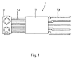
- FIG. 1 shows a sensor module 1, which consists of a magnetoresistive sensor 12 and an evaluation circuit 13 is.
- the sensor 12 is at the end of a Leadframe assembly 14 is arranged, which preferably a fine stamping frame is.
- the sensor 12th connected to the evaluation circuit 13.
- the evaluation circuit 13 is the evaluation circuit 13 with other electronic Circuit devices connectable.
- the laterally projecting from the sensor housings 12 and 22 components 15 and 25 of the lead frame assembly 14 serve as markers for exact Positioning of the sensor module 1 in the measuring field.
- the sensor 12 is designed as a magnetoresistive angle sensor and consists of two resistance bridges whose sinusoidal output signals are around 90 Degrees are out of phase.
- the transmitter 13 determines the angular position while allowing offset compensation of the angle sensor.
- connection 14a provided while the transmitter 13 five output terminals 14b for communication with external devices having.
- lead frame connections 14a and 14b both sensor signals, control signals and power signals, such as the operating voltage transfer.
- this sensor module 11 can arbitrarily be adapted to the installation location, in which the fingers 14a between the sensor 12th and evaluation 13 are bent, which the example of Figure 2 and 3 will be explained in more detail.
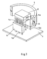
- FIG. It consists of two sensor units 1 and 2, which are constructed identically. There is the sensor unit 1 from the sensor 12, the connections 14a, the transmitter 13 and their terminals 14b.
- the second sensor unit 2 is made also from a sensor 22 and is on the sheet metal stampings 24 a with the Evaluation electronics 23 connected, which in turn stamped sheet metal parts 24 b as Connection has.
- the two sensor units 1 and 2 are arranged so the sensors 12 and 22 lie on top of each other and the evaluation electronics 13 and 23 point away from each other.
- the terminals 14b and 24b of the two sensor units properly in lie a plane, the connections 24a of the second sensor unit 2 between sensor 22 and evaluation circuit 23 twice by approximately 90 Degree bent.
- the sensors 12, 22 extends according to the longitudinal direction of the Sensor units 1, 2, a permanent magnet 5, whose magnetic field, the sensors 12 and 22 interspersed, wherein the position-dependent change of the magnetic field detected by the sensors 12 and 22 and as an output signal to the Evaluation circuits 13, 23 is supplied.
- the permanent magnet 5 is formed as a cylindrical body, wherein in the figure 3 for the sake of clarity, only a part of this magnet 5 shown is.
- the known sensors used to detect magnetic fields 12 and 22 only deliver at relatively high field strengths evaluable signals is one on the use of expensive materials in the manufacture of permanent magnets 5 instructed. For cost reasons, they try the cylindrical magnet 5 to be kept as small as possible.
- the redundant sensor units 1, 2 are arranged, which consists of the sensors 12 and 22, which are also arranged one above the other are.
- the Evaluation units 13 and 23 whose output terminals 14b or 24b are electrically connected to a circuit board 6.
- the sheet metal stampings 14a and 24a are bent approximately 90 in the sensor near 12, 22 and 90 degrees make such a very compact small sensor arrangement possible, what the cost of the entire system.
- the transmitter can analog or provide digital output signals, the transmitter to Zwekke Adjusting the bridges of the sensor and fixing the start and the end of the measuring range is programmable.
- the evaluation electronics is in addition to line and short circuit between the sensor head and evaluation also a loss of magnetic field strength detectable.
- the Ausensealgorythmus possible.
- the temperature of the Electronics monitored which in turn is readable.
- connection 14b or 24b can be connected to the connections 14b or 24b, which passive components or plug-in elements included attached become.
- the entire element is simply extrusion-coatable or in conventional joining techniques such as US E welding, wave soldering, conductive bonding, reflow soldering or laser processing editable.
Description
Die Erfindung betrifft ein Sensormodul, bei welchem ein Positionssensor mit einer Auswerteelektronik verbunden ist, die das von dem Positionssensor abgegebene, der Lage eines zu überwachenden Bauteiles entsprechende Signal aufbereitet.The invention relates to a sensor module in which a position sensor with an evaluation unit is connected, which outputs the output from the position sensor, the position of a component to be monitored corresponding signal edited.
Bei bekannten Sensoren wird das von dem Sensor abgegebene Signal einer Auswerteelektronik zugeführt, welche das Sensorsignal zur weiteren Verarbeitung durch eine angeschlossene Elektronik aufbereitet. So wird beispielsweise das Signal eines in einem Kraftfahrzeug angeordneten Positionssensors, welches die Veränderung der Position eines zu überwachenden Bauteiles, wie die Drosselklappe, repräsentiert, an eine Motorsteuerelektronik weitergeleitet, die auf der Grundlage des Sensorsignales ein Steuersignal für die Ansteuerung des Verbrennungsmotors erzeugt.In known sensors, the signal emitted by the sensor is a Transmitter supplied, which the sensor signal for further processing prepared by a connected electronics. For example the signal of a position sensor arranged in a motor vehicle, which the change in the position of a component to be monitored, such as Throttle, represented, passed to an engine control electronics, the on the basis of the sensor signal, a control signal for the control of the internal combustion engine generated.
In der Auswerteelektronik wird das Sensorsignal verstärkt und gewandelt und ein nullpunkt- und/oder temperaturkorrigiertes Ausgangssignal erzeugt.In the transmitter, the sensor signal is amplified and converted and generates a zero point and / or temperature corrected output signal.
Beim Einbau des Sensors und der Auswerteelektronik müssen beide aufeinander abgestimmt werden. Nach einem Vorabgleich beim jeweiligen Hersteller müssen die beiden Einzelteile beim Einbau in das Gerät, welches das positionsüberwachende Bauteil enthält, noch einmal aufeinander abgestimmt werden. Ein solcher Abgleich ist sehr aufwendig. Die örtliche Trennung von Sensor und Auswerteelektronik erfordert zusätzlichen Leitungsaufwand.When installing the sensor and the transmitter, both must face each other be matched. After a pre-adjustment at the respective manufacturer the two items must be installed in the device, which the position monitoring Component contains, once again matched. Such an adjustment is very expensive. The local separation of sensor and transmitter requires additional power.
Der Erfindung liegt somit die Aufgabe zugrunde, eine Sensoranordnung anzugeben, welche einfach und mit reduziertem Abgleichaufwand herstellbar ist. The invention is therefore based on the object of specifying a sensor arrangement, which can be produced easily and with reduced adjustment effort.
Erfindungsgemäß wird die Aufgabe dadurch gelöst, dass der Positionssensor und die Auswerteelektronik gemeinsam an oder auf einem Blechformteil angeordnet sind, wobei das Blechformteil mindestens zwischen Sensor und Auswerteelektronik zu deren elektrischer Verbindung als Leiterbahnstruktur ausgebildet ist, welche zur Anpassung an den Einbauort des Sensors abgewinkelt ist.According to the invention the object is achieved in that the position sensor and the transmitter arranged together on or on a sheet metal part are, wherein the sheet metal part at least between the sensor and transmitter formed to the electrical connection as a conductor track structure is, which is angled for adaptation to the installation location of the sensor.
Der Vorteil der Erfindung besteht darin, dass durch die Anordnung auf einem Blechformteil eine genaue Plazierung des Sensors an dem zu überwachenden Bauteil möglich ist. Auf Leitungsverbindungen zwischen Sensor und Auswerteelektronik kann verzichtet werden, wodurch die Bauform des Moduls verkleinert wird. Sensor und Auswerteelektronik werden in einem Schritt gemeinsam abgeglichen. Ein so geschaffenes Positionssensormodul ist nicht nur einfach im Offset und Meßbereich programmierbar, sondern kann auch zu Diagnosezwekken verwendet werden, wie beispielsweise zur Feststellung eines Leitungsbruchs oder Kurzschlusses zwischen Sensor und Auswerteelektronik. Durch Verbiegen des Blechformteils, im Bereich der Verbindung zwischen Sensor und Auswerteelektronik, kann das Sensormodul einer beliebigen Einbaugeometrie angepaßt werden.The advantage of the invention is that by the arrangement on a Sheet metal part accurate placement of the sensor to be monitored Component is possible. On line connections between sensor and transmitter can be omitted, which reduces the design of the module becomes. Sensor and transmitter become common in one step adjusted. Such a created position sensor module is not only easy in Offset and measuring range programmable, but can also for Diagnosezwekken used, such as to determine a line break or short circuit between sensor and transmitter. By Bending of the sheet metal part, in the area of the connection between sensor and Evaluation electronics, the sensor module of any mounting geometry be adjusted.
In einer bevorzugten Ausführuhgsform ist der Sensor als magnetoresistiver Sensor ausgebildet, welcher in einem Magnetfeld angeordnet ist.In a preferred embodiment, the sensor is magnetoresistive Sensor is formed, which is arranged in a magnetic field.
Vorteilhafterweise ist der Sensor annähernd im Zentrum eines zylinderförmig ausgebildeten Dauermagneten angeordnet. Durch die Abwinklung des Blechformteiles ist eine genaue Plazierung des Sensors im homogenen Teil des Magnetfeldes möglich.Advantageously, the sensor is approximately in the center of a cylindrical arranged permanent magnet arranged. By bending the sheet metal part is an accurate placement of the sensor in the homogeneous part of the magnetic field possible.
Bei einer vorteilhaften Ausgestaltung ist der Sensor an einem ersten äußeren Ende des Blechformteiles arretiert, wobei das die Auswerteelektronik in eine dem Sensor entgegengesetzte Richtung überragende Ende des Blechformteiles von mindestens einer frei endenden Leiterbahn des Blechformteiles gebildet ist. Auf diese Art und Weise ist ein einfacher elektrischer Anschluß des Blechformteiles an andere elektrische Schaltungen möglich. In an advantageous embodiment, the sensor is at a first outer Locked the end of the sheet metal part, wherein the evaluation in a the sensor opposite direction superior end of the sheet metal part formed by at least one free-ending conductor track of the sheet metal part is. In this way is a simple electrical connection of the sheet metal part to other electrical circuits possible.
In einer Weiterbildung der Erfindung ist das freie Ende des Blechformteiles elektrisch mit einem zweiten, passive elektrische Bauelemente tragenden Blechformteil verbunden, an welchem die Kontakteinrichtung ausgeformt ist. Aufgrund der Verwendung von Blechformteilen können für den konkreten Einsatzfall notwendige Bauelemente auf diesem angeordnet und elektrisch über das Blechformteil miteinander verbunden werden und bilden somit eine kompakte Einrichtung, welche insbesondere für den Einsatz in Kraftfahrzeugen erschütterungsfrei gelagert ist. Diese beiden Blechformteile können mit üblichen Verbindungstechniken, wie Schweißen oder Löten, kontaktiert werden, sowie zum Schutz vor korrosiven Einflüssen umspritzt, vergossen oder gehäust werden.In one embodiment of the invention, the free end of the sheet metal part electrically carrying a second, passive electrical components Connected sheet metal part on which the contact device is formed. Due to the use of sheet metal parts can be for the specific application necessary components arranged on this and electrically over the sheet metal part are joined together and thus form a compact Device which vibration-free, especially for use in motor vehicles is stored. These two sheet metal parts can with usual Connection techniques, such as welding or soldering, are contacted, as well as To protect against corrosive influences are molded, shed or housed.
Vorteilhafterweise können die Kontakteinrichtung oder das freie Ende der Leiterbahn selbst als Steckeinrichtung ausgebildet sein, wodurch auf das Befestigen eines separaten Steckers verzichtet werden kann.Advantageously, the contact device or the free end of the conductor track itself be designed as a plug-in device, thereby fixing on the a separate plug can be dispensed with.
Zum Schutz des Sensors bzw. der Auswerteelektronik beim Einbau in den Einsatzort, beispielsweise in ein Kraftfahrzeug sind der Sensor und die Auswerteelektronik separat gehäust.To protect the sensor or the evaluation electronics when installed in the place of use, For example, in a motor vehicle, the sensor and the transmitter housed separately.
Zur Herstellung redundanter Ausgangssignale liefernden Positionssensormoduls sind eine erste und eine zweite identisch aufgebaute, jeweils aus einem Sensor, einem Blechformteil und einer Auswerteelektronik bestehende Sensoreinheit vorhanden, wobei das Blechformteil jeder Sensoreinheit zwischen Sensor und Auswerteelektronik annähernd um 90 Grad abgewinkelt ist und die beiden Sensoreinheiten so in dem zylindrisch ausgebildeten Magneten eingeführt sind, dass die Sensoren unmittelbar übereinander liegend angeordnet sind, während die Auswerteelektroniken der beiden Sensoreinheiten sich gegenüber liegend jeweils dezentral, außerhalb der Sensorabmessungen angeordnet sind.To produce redundant output signals position sensor module are a first and a second identically constructed, each of a Sensor, a sheet metal part and an evaluation existing sensor unit present, wherein the sheet metal part of each sensor unit between Sensor and transmitter is angled approximately 90 degrees and the both sensor units inserted in the cylindrically shaped magnet are that the sensors are arranged directly above each other while the evaluation electronics of the two sensor units face each other lying in each case decentralized, arranged outside the sensor dimensions are.
Die Erfindung läßt zahlreiche Ausführungsformen zu. Eine davon soll anhand der in der Zeichnung dargestellten Figuren näher erläutert werden. The invention allows numerous embodiments. One of them should be based the figures shown in the drawing will be explained in more detail.
Es zeigen:
- Fig. 1:
- Eine nicht beanspruchte Ausführungsform eines Positionssensormodules
- Fig. 2:
- erste Ausführung des erfindungsgemäßen Positionssensormodules
- Fig. 3:
- zweite Ausführungsform des erfindungsgemäßen Positionssensormodules
- Fig. 1:
- An unclaimed embodiment of a position sensor module
- Fig. 2:
- first embodiment of the position sensor module according to the invention
- 3:
- second embodiment of the position sensor module according to the invention
Gleiche Merkmale sind mit gleichen Bezugszeichen gekennzeichnet.Identical features are identified by the same reference numerals.
Figur 1 zeigt ein Sensormodul 1, welches aus einem magnetoresistiven Sensor
12 und einer Auswerteschaltung 13 besteht. Der Sensor 12 ist am Ende einer
Leadframe-Anordnung 14 angeordnet, welche vorzugsweise ein Feinstanzrahmen
ist. Über die Finger 14a der Leadframe-Anordnung 14 ist der Sensor 12
mit der Auswerteschaltung 13 verbunden. Über die aus der Auswerteschaltung
13 entgegengesetzt zum Sensor 12 herausragenden freien Enden 14b der
Leadframe-Anordnung 14 ist die Auswerteschaltung 13 mit anderen elektronischen
Schaltungseinrichtungen verbindbar.FIG. 1 shows a sensor module 1, which consists of a
Die aus den Sensorgehäusen 12 und 22 seitlich herausragenden Bestandteile
15 und 25 der Lead-Frame-Anordnung 14 dienen als Markierungen zur exakten
Positionierung des Sensormoduls 1 im Meßfeld.The laterally projecting from the
Der Sensor 12 ist als magnetoresistiver Winkelsensor ausgebildet und besteht
aus zwei Widerstandsbrücken, deren sinusförmige Ausgangssignale um 90
Grad phasenverschoben sind. Die Auswerteelektronik 13 bestimmt die Winkelposition
und ermöglicht gleichzeitig eine Offsetkompensation des Winkelsensors.The
Zwischen dem mit einem Gehäuse versehenen Sensor 12 und der ebenfalls
separat gehäusten Auswerteelektronik 13 sind bei der vorliegenden Ausführungsform
sechs Verbindungen 14a vorgesehen, während die Auswerteelektronik
13 fünf Ausgangsanschlüsse 14b zur Kommunikation mit externen Einrichtungen
aufweist. Über die Leadframe-Verbindungen 14a und 14b werden
sowohl Sensorsignale, Steuersignale als auch Leistungssignale, wie die Betriebsspannung
übertragen.Between the provided with a
Aufgrund der Verbindung zwischen Sensor 12 und Auswerteelektronik 13 mittels
des Stanzbiegeteiles 14a und 14b kann dieses Sensormodul 11 beliebig an
den Einbauort angepaßt werden, in dem die Finger 14a zwischen Sensor 12
und Auswerteelektronik 13 gebogen werden, was am Beispiel von Figur 2 und 3
näher erläutert werden soll.Due to the connection between the
Ein redundantes System ist in Figur 2 dargestellt. Es besteht aus zwei Sensoreinheiten
1 und 2, welche identisch aufgebaut sind. Dabei besteht die Sensoreinheit
1 aus dem Sensor 12, den Verbindungen 14a, der Auswerteelektronik
13 sowie deren Anschlüssen 14b. Die zweite Sensoreinheit 2 besteht
ebenfalls aus einem Sensor 22 und ist über die Blechstanzteile 24a mit der
Auswerteelektronik 23 verbunden, welche wiederum Blechstanzteile 24b als
Anschluß aufweist. Die beiden Sensoreinheiten 1 und 2 sind so angeordnet,
dass die Sensoren 12 und 22 aufeinander liegen und die Auswerteelektroniken
13 bzw. 23 voneinander wegweisen.A redundant system is shown in FIG. It consists of two sensor units
1 and 2, which are constructed identically. There is the sensor unit
1 from the
Damit die Anschlüsse 14b bzw. 24b der beiden Sensoreinheiten einwandfrei in
einer Ebene liegen, sind die Verbindungen 24a der zweiten Sensoreinheit 2
zwischen Sensor 22 und Auswerteschaltung 23 zweimal um annähernd 90
Grad gebogen.Thus, the
Über den Sensoren 12, 22 erstreckt sich entsprechend der Längsrichtung der
Sensoreinheiten 1, 2 ein Permanentmagnet 5, dessen Magnetfeld die Sensoren
12 und 22 durchsetzt, wobei die positionsabhängige Änderung des Magnetfeldes
von den Sensoren 12 bzw. 22 erfaßt und als Ausgangssignal an die
Auswerteschaltungen 13, 23 geliefert wird.About the
Eine weitere Darstellung des erfindungsgemäßen Moduls ist in Figur 3 dargestellt.
Dabei ist der Dauermagnet 5 als zylindrischer Körper ausgebildet, wobei
in der Figur 3 der Übersicht halber nur ein Teil dieses Magneten 5 dargestellt
ist. Da die bekannten, zur Erfassung von Magnetfeldern verwendeten Sensoren
12 und 22, erst bei relativ hohen Feldstärken auswertbare Signale liefern, ist
man auf die Verwendung von teuren Materialien bei der Herstellung des Permanentmagneten
5 angewiesen. Aus Kostengründen bemüht man sich den
zylindrischen Magneten 5 so klein wie möglich zu halten. Im Zentrum des Magneten
5 sind die redundanten Sensoreinheiten 1, 2 angeordnet, welche aus
den Sensoren 12 und 22 besteht, die ebenfalls übereinander liegend angeordnet
sind. Außerhalb des Zentrums in Nähe der Wandung des Magneten 5 sind,
sich gegenüberstehend parallel zur Achse des zylindrischen Magneten 5 die
Auswerteeinheiten 13 bzw. 23 angeordnet, deren Ausgangsanschlüsse 14b
bzw. 24b elektrisch mit einer Leiterplatte 6 verbunden sind. Die Blechstanzteile
14a bzw. 24a sind annähernd in Sensornähe 12, 22 um 90 Grad gebogen und
machen so eine sehr kompakte kleine Sensoranordnung möglich, was die Kosten
des gesamten Systems relevant senkt.A further illustration of the module according to the invention is shown in FIG.
In this case, the
Je nach gewünschtem Anwendungsfall kann die Auswerteelektronik analoge oder digitale Ausgangssignale liefern, wobei die Auswerteelektronik zum Zwekke des Abgleichs der Brücken des Sensors und zur Festlegung des Anfangs und Endes des Meßbereichs programmierbar ist. Mit Hilfe der Auswerteelektronik ist neben Leitungs- und Kurzschluß zwischen Sensorkopf und Auswerteelektronik auch ein Verlust der Magnetfeldstärke detektierbar. Darüber hinaus sind nicht kompatible Sensorsignale feststellbar. Gleichzeitig ist eine Überwachung des Auswertealgorythmus möglich. Zusätzlich wird die Temperatur der Elektronik überwacht, die ihrerseits auslesbar ist.Depending on the desired application, the transmitter can analog or provide digital output signals, the transmitter to Zwekke Adjusting the bridges of the sensor and fixing the start and the end of the measuring range is programmable. With the help of the evaluation electronics is in addition to line and short circuit between the sensor head and evaluation also a loss of magnetic field strength detectable. Furthermore are incompatible sensor signals detectable. At the same time is a surveillance the Auswertealgorythmus possible. In addition, the temperature of the Electronics monitored, which in turn is readable.
Vorteilhafterweise können an die Anschlüsse 14b bzw. 24b weitere Leadframes,
welche passive Bauelemente bzw. Steckelemente enthalten angebracht
werden. Das Gesamtelement ist einfach umspritzbar bzw. in üblichen Fügetechniken
wie US-E-Schweißen, Wellenlöten, Leitkleben, Reflowlöten bzw. Laserbearbeitung
bearbeitbar.Advantageously, further leadframes can be connected to the
Claims (9)
- Sensor module in which a position sensor (12, 22) is connected to an electronic evaluation unit (13, 23) which conditions the signal output by the position sensor and corresponding to the position of an actuator, characterized in that the position sensor (12, 22) and the electronic evaluation unit (13, 23) are jointly arranged at or on a shaped sheet-metal part (14a, 14b; 24a, 24b), the shaped sheet-metal part (14a, 14b; 24a, 24b) being designed as a conductor track structure (14a, 24a), at least between the sensor (12, 22) and an electronic evaluation unit (13, 23) for the purpose of an electric connection, which conductor track structure is angled off to adapt to the installation site of the sensor (12, 22).
- Sensor module according to Claim 1, characterized in that the sensor (12, 22) is designed as a magnetoresistive sensor which is arranged in a magnetic field.
- Sensor module according to Claim 2, characterized in that the sensor (12, 22) is arranged approximately at the centre of a cylindrically designed permanent magnet (5).
- Sensor module according to Claim 1 or 2, characterized in that the sensor (12, 22) is positioned at a first outer end of the shaped sheet-metal part (14a, 14b; 24a, 24b), and in that the second end of the shaped sheet-metal part (14a, 14b; 24a, 24b), which project beyond the electronic evaluation unit (13, 23) in the opposite direction to the sensor (12, 22), is formed by at least one freely ending conductor track (14b, 24b).
- Sensor module according to Claim 4, characterized in that the free end (14b, 24b) of the shaped sheet-metal part (14a, 14b; 24a, 24b) is electrically connected to a second shaped sheet-metal part, which supports passive electric components and on which a contact device is constructed.
- Sensor module according to Claim 5, characterized in that the first and the second shaped sheet-metal parts are welded or soldered.
- Sensor module according to Claim 4 or 5, characterized in that the contact device or the free end of the conductor track (14b, 24b) is constructed as a plug-in device.
- Sensor module according to one of Claims 1 to 5, characterized in that the sensor (12, 22) and/or the electronic evaluation unit (13, 23) are separately housed.
- Sensor module according to one of Claims 1 to 5, characterized in that a first and a second identically constructed sensor unit (1, 2) respectively consisting of a sensor (12; 22), a shaped sheet-metal part (14a, 14b; 24a, 24b) and an electronic evaluation unit (13; 23) are present, the shaped sheet-metal part (14a, 14b; 24a, 24b) of each sensor unit being bent by approximately 90 degrees between the sensor and electronic evaluation unit, and the two sensor units (1, 2) being inserted into the cylindrically designed permanent magnet (5) such that the sensors (12; 22) are arranged lying immediately one above another, while the electronic evaluation units (13; 23) are arranged decentrally outside the sensor dimensions.
Applications Claiming Priority (2)
| Application Number | Priority Date | Filing Date | Title |
|---|---|---|---|
| DE20018538U | 2000-10-27 | ||
| DE20018538U DE20018538U1 (en) | 2000-10-27 | 2000-10-27 | sensor module |
Publications (2)
| Publication Number | Publication Date |
|---|---|
| EP1202024A1 EP1202024A1 (en) | 2002-05-02 |
| EP1202024B1 true EP1202024B1 (en) | 2005-03-23 |
Family
ID=7948265
Family Applications (1)
| Application Number | Title | Priority Date | Filing Date |
|---|---|---|---|
| EP01125622A Expired - Lifetime EP1202024B1 (en) | 2000-10-27 | 2001-10-26 | Sensor module with stamped sheet metal part ( magneto resistive throttle valve sensor ) |
Country Status (3)
| Country | Link |
|---|---|
| US (1) | US6593732B2 (en) |
| EP (1) | EP1202024B1 (en) |
| DE (2) | DE20018538U1 (en) |
Cited By (2)
| Publication number | Priority date | Publication date | Assignee | Title |
|---|---|---|---|---|
| US8629520B2 (en) | 2006-01-20 | 2014-01-14 | Allegro Microsystems, Llc | Arrangements for an integrated sensor |
| US10935612B2 (en) | 2018-08-20 | 2021-03-02 | Allegro Microsystems, Llc | Current sensor having multiple sensitivity ranges |
Families Citing this family (23)
| Publication number | Priority date | Publication date | Assignee | Title |
|---|---|---|---|---|
| JP3794937B2 (en) * | 2001-05-30 | 2006-07-12 | 株式会社日立製作所 | Rotation detector |
| DE10233080A1 (en) * | 2002-07-19 | 2004-02-12 | Fernsteuergeräte Kurt Oelsch GmbH | sensor device |
| TW557610B (en) * | 2002-07-31 | 2003-10-11 | Fci Asia Technology Pte Ltd | Sensor module for card connector and card connector having such sensor module |
| KR20050069078A (en) * | 2003-12-30 | 2005-07-05 | 현대자동차주식회사 | Fuel injection control method of engine |
| EP1712926B1 (en) | 2004-02-02 | 2011-11-02 | Aisan Kogyo Kabushiki Kaisha | Rotating angle sensor, method of manufacturing the sensor, and throttle control device having the rotating angle sensor |
| JP2007523336A (en) * | 2004-02-24 | 2007-08-16 | プレットル,ロルフ | Sensor holder and manufacturing method thereof |
| US20070169551A1 (en) * | 2005-06-13 | 2007-07-26 | Analog Devices, Inc. | MEMS Sensor System with Configurable Signal Module |
| WO2007041465A1 (en) * | 2005-09-29 | 2007-04-12 | Timken Us Corporation | Redundant angle sensor |
| DE102005060713B4 (en) * | 2005-12-19 | 2019-01-24 | Austriamicrosystems Ag | Magnetic field sensor arrangement and method for non-contact measurement of a magnetic field |
| US20080110435A1 (en) * | 2006-11-13 | 2008-05-15 | Oswald Baasch | Air valve and method of use |
| ATE430913T1 (en) * | 2006-11-21 | 2009-05-15 | Fiat Ricerche | METHOD AND DEVICE FOR DETERMINING THE RELATIVE POSITION OF TWO MOBILE ELEMENTS TO EACH OTHER |
| US8933691B2 (en) * | 2007-10-27 | 2015-01-13 | Walbro Engine Management, L.L.C. | Rotary position sensor |
| US8857464B2 (en) | 2008-01-30 | 2014-10-14 | Flowserve Management Company | Valve actuators having magnetic angle sensors |
| US8686717B2 (en) * | 2008-09-08 | 2014-04-01 | GM Global Technology Operations LLC | Position sensor arrangement |
| DE102010020230B4 (en) * | 2010-05-11 | 2012-03-01 | Pierburg Gmbh | Actuator with sensor, plug-in tool and a method for positioning the sensor |
| DE102010047128A1 (en) * | 2010-09-30 | 2012-04-05 | Infineon Technologies Ag | Hall sensor arrangement for redundantly measuring a magnetic field |
| DE102013213053A1 (en) * | 2013-07-04 | 2015-01-08 | Continental Automotive Gmbh | Angle of rotation sensor device with redundant sensor units |
| CN106662606B (en) * | 2014-07-22 | 2020-03-17 | 阿托普有限公司 | Method and device for determining the resistance of a coil connection of an armature coil |
| JP6759704B2 (en) * | 2016-05-19 | 2020-09-23 | 株式会社ジェイテクト | Sensor unit and sensor device |
| CN109642782B (en) * | 2016-08-02 | 2021-08-10 | 伺服感应(Smc)有限公司 | High resolution absolute encoder |
| JP2018040586A (en) * | 2016-09-05 | 2018-03-15 | 株式会社デンソー | Angle detection mechanism and angle detection system |
| EP3457154B1 (en) | 2017-09-13 | 2020-04-08 | Melexis Technologies SA | Stray field rejection in magnetic sensors |
| US11567108B2 (en) | 2021-03-31 | 2023-01-31 | Allegro Microsystems, Llc | Multi-gain channels for multi-range sensor |
Family Cites Families (23)
| Publication number | Priority date | Publication date | Assignee | Title |
|---|---|---|---|---|
| JPS54148578A (en) * | 1978-04-18 | 1979-11-20 | Nec Corp | Rotating direction detector |
| JPS57193094A (en) * | 1981-05-18 | 1982-11-27 | Matsushita Electric Ind Co Ltd | Electronic circuit part and method of mounting same |
| JPH0285324U (en) * | 1988-12-21 | 1990-07-04 | ||
| JPH04284661A (en) * | 1991-03-13 | 1992-10-09 | Toshiba Corp | Semiconductor device |
| DE4123407A1 (en) * | 1991-07-15 | 1993-01-21 | Holzer Walter | Compact HF current supply, esp. for lap top computer or fax machine - has components mounted on foldable circuit board halves which, when folded, cause components to face each other |
| JP3206204B2 (en) * | 1992-05-22 | 2001-09-10 | 株式会社デンソー | Throttle position sensor |
| WO1995017680A1 (en) * | 1993-12-22 | 1995-06-29 | Itt Automotive Europe Gmbh | Device for detecting rotary or angular movements |
| DE4404265C3 (en) * | 1994-02-10 | 2001-02-15 | Siemens Ag | Method of manufacturing a calibrated sensor unit |
| US6169254B1 (en) * | 1994-07-20 | 2001-01-02 | Honeywell, Inc. | Three axis sensor package on flexible substrate |
| JP3637634B2 (en) * | 1994-08-25 | 2005-04-13 | 株式会社デンソー | Position sensor |
| JP3395402B2 (en) * | 1994-10-14 | 2003-04-14 | 住友電気工業株式会社 | Travel detector |
| US5488294A (en) * | 1995-01-18 | 1996-01-30 | Honeywell Inc. | Magnetic sensor with means for retaining a magnet at a precise calibrated position |
| DE19505759C2 (en) * | 1995-02-20 | 1997-02-13 | Siemens Ag | Switches with a Hall Difference IC for contactless position detection, especially in the automotive sector |
| US5581179A (en) * | 1995-05-31 | 1996-12-03 | Allegro Microsystems, Inc. | Hall-effect ferrous-article-proximity sensor assembly |
| US5670876A (en) * | 1995-11-14 | 1997-09-23 | Fisher Controls International, Inc. | Magnetic displacement sensor including first and second flux paths wherein the first path has a fixed reluctance and a sensor disposed therein |
| US5631557A (en) * | 1996-02-16 | 1997-05-20 | Honeywell Inc. | Magnetic sensor with encapsulated magnetically sensitive component and magnet |
| US5912556A (en) * | 1996-11-06 | 1999-06-15 | Honeywell Inc. | Magnetic sensor with a chip attached to a lead assembly within a cavity at the sensor's sensing face |
| US6003369A (en) * | 1997-05-19 | 1999-12-21 | Continental Teves, Inc. | Method for manufacturing encapsulated semiconductor devices |
| US5963028A (en) * | 1997-08-19 | 1999-10-05 | Allegro Microsystems, Inc. | Package for a magnetic field sensing device |
| DE19747177C2 (en) * | 1997-10-07 | 2003-08-21 | Fraunhofer Ges Forschung | Housing component and method for its production |
| JPH11304894A (en) * | 1998-04-23 | 1999-11-05 | Mitsubishi Electric Corp | Magnetism detection device, and manufacture thereof |
| DE19902188A1 (en) * | 1999-01-21 | 2000-07-27 | Philips Corp Intellectual Pty | Arrangement for speed measurement |
| US6455907B1 (en) * | 2000-09-14 | 2002-09-24 | Delphi Technologies, Inc. | Magnetoresistive sensor assembly and method for manufacturing same |
-
2000
- 2000-10-27 DE DE20018538U patent/DE20018538U1/en not_active Expired - Lifetime
-
2001
- 2001-10-26 EP EP01125622A patent/EP1202024B1/en not_active Expired - Lifetime
- 2001-10-26 DE DE50105676T patent/DE50105676D1/en not_active Expired - Lifetime
- 2001-10-31 US US10/004,298 patent/US6593732B2/en not_active Expired - Lifetime
Cited By (6)
| Publication number | Priority date | Publication date | Assignee | Title |
|---|---|---|---|---|
| US8629520B2 (en) | 2006-01-20 | 2014-01-14 | Allegro Microsystems, Llc | Arrangements for an integrated sensor |
| US8952471B2 (en) | 2006-01-20 | 2015-02-10 | Allegro Microsystems, Llc | Arrangements for an integrated sensor |
| US9082957B2 (en) | 2006-01-20 | 2015-07-14 | Allegro Microsystems, Llc | Arrangements for an integrated sensor |
| US9859489B2 (en) | 2006-01-20 | 2018-01-02 | Allegro Microsystems, Llc | Integrated circuit having first and second magnetic field sensing elements |
| US10069063B2 (en) | 2006-01-20 | 2018-09-04 | Allegro Microsystems, Llc | Integrated circuit having first and second magnetic field sensing elements |
| US10935612B2 (en) | 2018-08-20 | 2021-03-02 | Allegro Microsystems, Llc | Current sensor having multiple sensitivity ranges |
Also Published As
| Publication number | Publication date |
|---|---|
| EP1202024A1 (en) | 2002-05-02 |
| DE50105676D1 (en) | 2005-04-28 |
| US20020067162A1 (en) | 2002-06-06 |
| DE20018538U1 (en) | 2002-03-07 |
| US6593732B2 (en) | 2003-07-15 |
Similar Documents
| Publication | Publication Date | Title |
|---|---|---|
| EP1202024B1 (en) | Sensor module with stamped sheet metal part ( magneto resistive throttle valve sensor ) | |
| EP1435524B1 (en) | Battery sensor device | |
| EP1397853B1 (en) | Relay support device for an electric motor, in particular for an electrically commutated dc motor | |
| DE19618538C2 (en) | rotation sensor | |
| EP2845299B1 (en) | Dc motor for driving assemblies of a motor vehicle | |
| EP1320177A2 (en) | Circuit board for electric motor and such electric motor | |
| DE102006046984A1 (en) | Method for producing a carrier element with an angle sensor | |
| WO2014060174A1 (en) | Connection element for a drive arrangement and a drive arrangement having a connection part | |
| DE10007868B4 (en) | Electronic control circuit | |
| DE4320939A1 (en) | poetry | |
| DE102012211749A1 (en) | Measuring resistor for current sensor and current sensor unit | |
| EP3109951B1 (en) | Electrical component, connection unit with at least one electrical component, vehicle using the same, and method for producing an electrical component | |
| DE112020003914T5 (en) | Electrically powered traction device and method of assembling an electrically powered traction device | |
| EP2347221A1 (en) | Device for detecting a rotational angle of a rotatable part | |
| DE19649906C2 (en) | Sensor for detecting angles of rotation | |
| WO2003098226A1 (en) | Support for an electronic component and a method for the production thereof | |
| DE19835782A1 (en) | Ultrasonic transducer with a circuit board arranged in the longitudinal direction of the transducer for an electrical circuit | |
| DE102020214483A1 (en) | Torque and angle sensor | |
| DE10249683B4 (en) | Contact terminal for the electr. Contacting a mating contact, esp. For use in electrical motor vehicle components, such as. Window lift systems o. The like. | |
| EP1776518A1 (en) | Sensor for measuring the position of an actuator | |
| WO2007054557A1 (en) | Sensor module | |
| DE102018104886B3 (en) | Electromechanical suspension actuator | |
| WO2008125371A1 (en) | Contact system with vibration damper for current measuring instruments | |
| EP1519145B1 (en) | Arrangement with a sensor | |
| WO1991009408A1 (en) | Angle of rotation potentiometer |
Legal Events
| Date | Code | Title | Description |
|---|---|---|---|
| PUAI | Public reference made under article 153(3) epc to a published international application that has entered the european phase |
Free format text: ORIGINAL CODE: 0009012 |
|
| AK | Designated contracting states |
Kind code of ref document: A1 Designated state(s): AT BE CH CY DE DK ES FI FR GB GR IE IT LI LU MC NL PT SE TR Kind code of ref document: A1 Designated state(s): DE FR GB |
|
| AX | Request for extension of the european patent |
Free format text: AL;LT;LV;MK;RO;SI |
|
| 17P | Request for examination filed |
Effective date: 20020603 |
|
| AKX | Designation fees paid |
Free format text: DE FR GB |
|
| GRAP | Despatch of communication of intention to grant a patent |
Free format text: ORIGINAL CODE: EPIDOSNIGR1 |
|
| GRAS | Grant fee paid |
Free format text: ORIGINAL CODE: EPIDOSNIGR3 |
|
| GRAA | (expected) grant |
Free format text: ORIGINAL CODE: 0009210 |
|
| AK | Designated contracting states |
Kind code of ref document: B1 Designated state(s): DE FR GB |
|
| REG | Reference to a national code |
Ref country code: GB Ref legal event code: FG4D Free format text: NOT ENGLISH |
|
| REG | Reference to a national code |
Ref country code: IE Ref legal event code: FG4D Free format text: GERMAN |
|
| REF | Corresponds to: |
Ref document number: 50105676 Country of ref document: DE Date of ref document: 20050428 Kind code of ref document: P |
|
| GBT | Gb: translation of ep patent filed (gb section 77(6)(a)/1977) |
Effective date: 20050516 |
|
| PLBE | No opposition filed within time limit |
Free format text: ORIGINAL CODE: 0009261 |
|
| STAA | Information on the status of an ep patent application or granted ep patent |
Free format text: STATUS: NO OPPOSITION FILED WITHIN TIME LIMIT |
|
| ET | Fr: translation filed | ||
| 26N | No opposition filed |
Effective date: 20051227 |
|
| REG | Reference to a national code |
Ref country code: FR Ref legal event code: TP |
|
| REG | Reference to a national code |
Ref country code: GB Ref legal event code: 732E Free format text: REGISTERED BETWEEN 20110825 AND 20110831 |
|
| PGFP | Annual fee paid to national office [announced via postgrant information from national office to epo] |
Ref country code: GB Payment date: 20141021 Year of fee payment: 14 |
|
| REG | Reference to a national code |
Ref country code: FR Ref legal event code: PLFP Year of fee payment: 15 |
|
| GBPC | Gb: european patent ceased through non-payment of renewal fee |
Effective date: 20151026 |
|
| PG25 | Lapsed in a contracting state [announced via postgrant information from national office to epo] |
Ref country code: GB Free format text: LAPSE BECAUSE OF NON-PAYMENT OF DUE FEES Effective date: 20151026 |
|
| REG | Reference to a national code |
Ref country code: FR Ref legal event code: PLFP Year of fee payment: 16 |
|
| REG | Reference to a national code |
Ref country code: FR Ref legal event code: PLFP Year of fee payment: 17 |
|
| REG | Reference to a national code |
Ref country code: FR Ref legal event code: PLFP Year of fee payment: 18 |
|
| PGFP | Annual fee paid to national office [announced via postgrant information from national office to epo] |
Ref country code: FR Payment date: 20191028 Year of fee payment: 19 |
|
| REG | Reference to a national code |
Ref country code: DE Ref legal event code: R084 Ref document number: 50105676 Country of ref document: DE |
|
| REG | Reference to a national code |
Ref country code: DE Ref legal event code: R081 Ref document number: 50105676 Country of ref document: DE Owner name: VITESCO TECHNOLOGIES GMBH, DE Free format text: FORMER OWNER: CONTINENTAL AUTOMOTIVE GMBH, 30165 HANNOVER, DE |
|
| PGFP | Annual fee paid to national office [announced via postgrant information from national office to epo] |
Ref country code: DE Payment date: 20201031 Year of fee payment: 20 |
|
| PG25 | Lapsed in a contracting state [announced via postgrant information from national office to epo] |
Ref country code: FR Free format text: LAPSE BECAUSE OF NON-PAYMENT OF DUE FEES Effective date: 20201031 |
|
| REG | Reference to a national code |
Ref country code: DE Ref legal event code: R071 Ref document number: 50105676 Country of ref document: DE |
|
| REG | Reference to a national code |
Ref country code: DE Ref legal event code: R081 Ref document number: 50105676 Country of ref document: DE Owner name: VITESCO TECHNOLOGIES GMBH, DE Free format text: FORMER OWNER: VITESCO TECHNOLOGIES GMBH, 30165 HANNOVER, DE |