EP1201996B1 - Méthode et appareil pour diminuer les émissions d'une chambre de combustion - Google Patents
Méthode et appareil pour diminuer les émissions d'une chambre de combustion Download PDFInfo
- Publication number
- EP1201996B1 EP1201996B1 EP01308183A EP01308183A EP1201996B1 EP 1201996 B1 EP1201996 B1 EP 1201996B1 EP 01308183 A EP01308183 A EP 01308183A EP 01308183 A EP01308183 A EP 01308183A EP 1201996 B1 EP1201996 B1 EP 1201996B1
- Authority
- EP
- European Patent Office
- Prior art keywords
- fuel
- combustor
- mixer
- stage
- pilot
- Prior art date
- Legal status (The legal status is an assumption and is not a legal conclusion. Google has not performed a legal analysis and makes no representation as to the accuracy of the status listed.)
- Expired - Lifetime
Links
Images
Classifications
-
- F—MECHANICAL ENGINEERING; LIGHTING; HEATING; WEAPONS; BLASTING
- F23—COMBUSTION APPARATUS; COMBUSTION PROCESSES
- F23R—GENERATING COMBUSTION PRODUCTS OF HIGH PRESSURE OR HIGH VELOCITY, e.g. GAS-TURBINE COMBUSTION CHAMBERS
- F23R3/00—Continuous combustion chambers using liquid or gaseous fuel
- F23R3/28—Continuous combustion chambers using liquid or gaseous fuel characterised by the fuel supply
- F23R3/286—Continuous combustion chambers using liquid or gaseous fuel characterised by the fuel supply having fuel-air premixing devices
-
- F—MECHANICAL ENGINEERING; LIGHTING; HEATING; WEAPONS; BLASTING
- F23—COMBUSTION APPARATUS; COMBUSTION PROCESSES
- F23R—GENERATING COMBUSTION PRODUCTS OF HIGH PRESSURE OR HIGH VELOCITY, e.g. GAS-TURBINE COMBUSTION CHAMBERS
- F23R3/00—Continuous combustion chambers using liquid or gaseous fuel
- F23R3/02—Continuous combustion chambers using liquid or gaseous fuel characterised by the air-flow or gas-flow configuration
- F23R3/04—Air inlet arrangements
- F23R3/10—Air inlet arrangements for primary air
- F23R3/12—Air inlet arrangements for primary air inducing a vortex
- F23R3/14—Air inlet arrangements for primary air inducing a vortex by using swirl vanes
-
- F—MECHANICAL ENGINEERING; LIGHTING; HEATING; WEAPONS; BLASTING
- F23—COMBUSTION APPARATUS; COMBUSTION PROCESSES
- F23R—GENERATING COMBUSTION PRODUCTS OF HIGH PRESSURE OR HIGH VELOCITY, e.g. GAS-TURBINE COMBUSTION CHAMBERS
- F23R3/00—Continuous combustion chambers using liquid or gaseous fuel
- F23R3/28—Continuous combustion chambers using liquid or gaseous fuel characterised by the fuel supply
- F23R3/34—Feeding into different combustion zones
- F23R3/343—Pilot flames, i.e. fuel nozzles or injectors using only a very small proportion of the total fuel to insure continuous combustion
Definitions
- This application relates generally to combustors and, more particularly, to gas turbine combustors.
- NOx oxides of nitrogen
- HC unburned hydrocarbons
- CO carbon monoxide
- engine emissions fall into two classes: those formed because of high flame temperatures (NOx), and those formed because of low flame temperatures which do not allow the fuel-air reaction to proceed to completion (HC & CO).
- NOx high flame temperatures
- HC & CO low flame temperatures which do not allow the fuel-air reaction to proceed to completion
- the reactants must be well mixed, so that burning occurs evenly across the mixture without hot spots, where NOx is produced, or cold spots, when CO and HC are produced.
- Hot spots are produced where the mixture of fuel and air is near a specific ratio when all fuel and air react (i.e. no unburned fuel or air is present in the products). This mixture is called stoichiometric. Cold spots can occur if either excess air is present (called lean combustion), or if excess fuel is present (called rich combustion).
- Modern gas turbine combustors consist of between 10 and 30 mixers, which mix high velocity air with a fine fuel spray. These mixers usually consist of a single fuel injector located at a center of a swirler for swirling the incoming air to enhance flame stabilization and mixing. Both the fuel injector and mixer are located on a combustor dome.
- the fuel to air ratio in the mixer is rich. Since the overall combustor fuel-air ratio of gas turbine combustors is lean, additional air is added through discrete dilution holes prior to exiting the combustor. Poor mixing and hot spots can occur both at the dome, where the injected fuel must vaporize and mix prior to burning, and in the vicinity of the dilution holes, where air is added to the rich dome mixture.
- rich dome combustors are very stable devices with wide flammability limits and can produce low HC and CO emissions, and acceptable NOx emissions.
- rich dome combustors a fundamental limitation on rich dome combustors exists, since the rich dome mixture must pass through stoichiometric or maximum NOx producing regions prior to exiting the combustor. This is particularly important because as the operating pressure ratio (OPR) of modern gas turbines increases for improved cycle efficiencies and compactness, combustor inlet temperatures and pressures increase the rate of NOx production dramatically. As emission standards become more stringent and OPR's increase, it appears unlikely that traditional rich dome combustors will be able to meet the challenge.
- OPR operating pressure ratio
- One state-of-the-art lean dome combustor is referred to as a dual annular combustor (DAC) because it includes two radially stacked mixers on each fuel nozzle which appear as two annular rings when viewed from the front of a combustor.
- the additional row of mixers allows tuning for operation at different conditions.
- the outer mixer is fueled, which is designed to operate efficiently at idle conditions.
- both mixers are fueled with the majority of fuel and air supplied to the inner annulus, which is designed to operate most efficiently and with few emissions at high power operation.
- EP 0 660 038 shows a fuel injection apparatus which produces reduced amounts of NOx emissions and US 4 498 288 shows how fuel staging results in reducing CO emissions.
- a combustor for a gas turbine engine operates with high combustion efficiency and low carbon monoxide, nitrous oxide, and smoke emissions during low, intermediate, and high engine power operations.
- the combustor includes a center mixer assembly and a second mixer assembly radially outward from the center mixer assembly.
- the center mixer assembly includes a pilot fuel injector, at least one swirler, and an air splitter.
- the second mixer assembly is circumferentially outward from the center mixer assembly and includes a plurality of mixers that include a swirler, an atomizer, and a venturi.
- the combustor also includes a fuel delivery system including a pilot fuel circuit that supplies fuel to the center mixer assembly and a main fuel circuit that includes at least two fuel stages to supply fuel to the second mixer assembly.
- the center mixer assembly aerodynamically isolates a pilot flame from a main stage of air.
- the combustor injects fuel only through the pilot fuel circuit directly into the center mixer assembly while channeling air through the second mixer assembly. Because the combustor operates using only the pilot fuel circuit during idle power operations, a high combustor idle power operating efficiency is maintained and combustor emissions are controlled.
- fuel is injected through both the pilot and main fuel circuits. The fuel is dispersed evenly throughout the combustor to maintain control of emissions generated during increased power operations.
- a combustor is provided which operates with a high combustion efficiency while controlling and maintaining low carbon monoxide, nitrous oxide, and smoke emissions during engine low, intermediate, and high power operations.
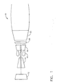
- Figure 1 is a schematic illustration of a gas turbine engine 10 including a low pressure compressor 12, a high pressure compressor 14, and a combustor 16.
- Engine 10 also includes a high pressure turbine 18 and a low pressure turbine 20.
- Airflow (not shown in Figure 1) from combustor 16 drives turbines 18 and 20.
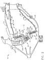
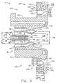
- Figure 2 is a cross-sectional view of combustor 16 for use with a gas turbine engine, similar to engine 10 shown in Figure 1, and Figure 3 is an enlarged view of combustor 16 taken along area 3.
- the gas turbine engine is a CFM engine available from General Electric Company, Cincinnati, Ohio.
- the gas turbine engine is a GE90 engine available from General Electric Company, Cincinnati, Ohio.
- Combustor 16 includes a center mixer assembly 36 and a second mixer assembly 38 disposed radially outward from center mixer assembly 36.
- Center mixer assembly 36 includes an outer wall 42, a pilot outer swirler 44, a pilot inner swirler 46, and a pilot fuel injector 48.
- Center mixer assembly 36 has an axis of symmetry 60, and is generally cylindrical-shaped with an annular cross-sectional profile (not shown).
- An inner flame (not shown), sometimes referred to as a pilot, is a spray diffusion flame fueled entirely from gas turbine start conditions.
- pilot fuel injector 48 supplies fuel through injection jets (not shown). In an alternative embodiment, pilot fuel injector 48 supplies fuel through injection simplex sprays (not shown).
- Pilot fuel injector 48 includes an axis of symmetry 62 and is positioned within center mixer assembly 36 such that fuel injector axis of symmetry 62 is substantially co-axial with center mixer assembly axis of symmetry 60.
- Fuel injector 48 injects fuel to the pilot and includes an intake side 64, a discharge side 66, and a body 68 extending between intake side 64 and discharge side 66.
- Discharge side 66 includes a convergent discharge nozzle 70 which directs a fuel-flow (not shown) outward from fuel injector 48 substantially parallel to center mixer assembly axis of symmetry 60.
- Pilot inner swirler 46 is annular and is circumferentially disposed around pilot fuel injector 48. Pilot inner swirler 46 includes an intake side 80 and an outlet side 82. An inner pilot airflow stream (not shown) enters pilot inner swirler intake side 80 and is accelerated prior to exiting through pilot inner swirler outlet side 82.
- a baseline air blast pilot splitter 90 is positioned downstream from pilot inner swirler 46.
- Baseline air blast pilot splitter 90 includes an upstream portion 92 and a downstream portion 94 extending from upstream portion 92.
- Upstream portion 92 includes a leading edge 96 and has a diameter 98 that is constant from leading edge 96 to air blast pilot splitter downstream portion 94.
- Upstream portion 92 also includes an inner surface 100 positioned substantially parallel and adjacent pilot inner swirler 46.
- Baseline air blast pilot splitter downstream portion 94 extends from upstream portion 92 to a trailing edge 103 of splitter 90. Downstream portion 94 is convergent towards center mixer assembly axis of symmetry 60 such at a mid-point 104 of downstream portion 94, downstream portion 94 has a diameter 106 that is less than upstream portion diameter 98. Downstream portion 94 diverges outward from downstream portion mid-point 104 such that trailing edge diameter 108 is larger than downstream portion mid-point diameter 106, but less than upstream portion diameter 98.
- Pilot outer swirler 44 extends substantially perpendicularly from baseline air blast pilot splitter 90 and attaches to a contoured wall 110.
- Contoured wall 110 is attached to center mixer assembly outer wall 42.
- Pilot outer swirler 44 is annular and is circumferentially disposed around baseline air blast pilot splitter 90.
- Contoured wall 110 includes an apex 156 positioned between a convergent section 158 of contoured wall 110 and a divergent section 160 of contoured wall 110.
- Splitter downstream portion 94 diverges towards contoured wall divergent section 160.
- Contoured wall 110 also includes a trailing edge 170 that extends from contoured wall divergent section 160. Trailing edge 170 is substantially perpendicular to center mixer assembly axis of symmetry 60 and is adjacent a combustion zone 172.
- Combustion zone 172 is formed by annular, radially outer and radially inner casing support members 174 and 176, respectively, and a combustor liner 178, respectively.
- Combustor liner 178 shields the outer and inner support members 174 and 176, respectively, from the heat generated within combustion zone 172 and includes an outer liner 180 and an inner liner 182.
- Outer liner 180 and inner liner 182 are annular and define combustion zone 172.
- Second mixer assembly 38 is radially outward from center mixer assembly 36 and extends circumferentially around center mixer assembly 36.
- second mixer assembly 38 is known as an Affordable Multiple Venturi (AMV).
- Second mixer assembly 38 includes a concentric array of mixers 190 positioned radially outward from center mixer assembly 36.
- combustor 16 includes three annular arrays of mixers 190 positioned between center mixer assembly 36 and combustion outer liner 180 and two annular arrays of mixers 190 positioned between center mixer assembly 36 and combustion inner liner 182.
- Each mixer 190 includes an atomizer 192, a venturi 194, and a swirler 196.
- Mixer 190 has a leading edge 200, a trailing edge 202, and an axis of symmetry 204.
- Mixers 190 are positioned such that leading edges 200 are substantially co-planar and such that trailing edges 202 are also substantially co-planar. Additionally, mixer trailing edges 202 are substantially co-planar with center mixer assembly contoured wall trailing edge 170.
- Each atomizer 192 has a length 206 extending between second mixer assembly leading edge 200 to a tip 208 of atomizer 192. Each atomizer 192 is positioned co-axially with respect to mixer assembly axis of symmetry 204 within each mixer assembly 38. In one embodiment, atomizers 192 are annular air blast simplex atomizers. Atomizers 192 are annular and are in flow communication with a fuel source (not shown). As fuel is supplied to second mixer assembly 38, atomizers 192 atomize the fuel prior to the atomized fuel entering combustion chamber 172.
- Swirlers 196 are annular and are radially outward from atomizers 192.
- swirlers 192 are single axial swirlers.
- swirlers 192 are radial swirlers.
- Swirlers 196 cause air flowing through second mixer assembly 38 to swirl to assist atomizers 192 in atomizing fuel and to cause fuel and air to mix thoroughly prior to entering combustion chamber 172.
- swirlers 196 induce airflow to swirl in a counter-clockwise direction.
- swirlers 196 induce airflow to swirl in a clockwise direction.
- swirlers 196 induce airflow to swirl in counter-clockwise and clockwise directions.
- Venturis 194 are annular and are radially outward from swirlers 196. Venturis 194 include a planar section 210, a converging section 212, and a diverging section 214. Planar section 210 is radially outward from and adjacent swirlers 196. Converging section 212 extends radially inward from planar section 210 to a venturi apex 216. Diverging section 214 extends radially outward from venturi apex 216 to a trailing edge 220 of venturi 194. In an alternative embodiment, venturi 194 only includes converging section 212 and does not include diverging section 214.
- Venturi apex 216 is located a distance 213 from second mixing assembly leading edge 200. Distance 213 is approximately equal atomizer length 206 such that each venturi apex 216 is in close proximity to atomizer tip 208. Accordingly, venturi converging section 212 directs airflow towards atomizer tip 208 to assist atomizer 192 in atomizing fuel and to ensure fuel and air mix thoroughly. Venturis 194 located adjacent center mixer assembly 36 extend from an outer surface 222 of outer wall 42.
- a fuel delivery system 230 supplies fuel to combustor 16 and includes a pilot fuel circuit 232 and a main fuel circuit 234. Pilot fuel circuit 232 supplies fuel to pilot fuel injector 48 and main fuel circuit 234 supplies fuel to second mixer assembly 38 and includes three independent fuel stages used to control nitrous oxide emissions generated within combustor 16.
- Mixers 190 located adjacent center mixer assembly 36 are radially inner mixers or first fuel stage mixers 240 and are supplied fuel during a first fuel stages.
- Mixers 190 located between radially inner mixers and combustor liner 178 are radially outer mixers 242 and are supplied fuel during second and third fuel stages. More specifically, mixers 190 located adjacent first fuel stage mixers 240 are second fuel stage mixers 244 and second mixer assemblies 38 located between second fuel stage mixers 244 and combustor liner 178 are third stage fuel mixers 246.
- pilot fuel circuit 232 injects fuel to combustor 16 through pilot fuel injector 48. Simultaneously, airflow enters pilot swirler intake 80 and is accelerated outward from pilot swirler outlet side 82 and additional airflow enters second mixer assembly 38 through swirlers 196.
- the pilot airflow flows substantially parallel to center mixer axis of symmetry 60 and strikes air splitter 90 which directs the pilot airflow in a swirling motion towards fuel exiting pilot fuel injector 48.
- the pilot airflow does not collapse a spray pattern (not shown) of pilot fuel injector 48, but instead stablizes and atomizes the fuel.
- the second mixer assembly airflow is directed through venturis 194 into combustion chamber 172.
- pilot fuel stage Utilizing only the pilot fuel stage permits combustor 16 to maintain low power operating efficiency and to control and minimize emissions exiting combustor 16. Because the pilot airflow is separated from the second mixer assembly airflow, the pilot fuel is completely ignited and burned, resulting in lean stability and low power emissions of carbon monoxide, hydrocarbons, and nitrous oxide.
- second mixer assembly 38 is supplied fuel with main fuel circuit 234. Initially, as power operating conditions are increased, the first fuel stage supplies fuel to first fuel stage mixers 240. Air flowing through second mixer assembly 38 and passing through first fuel stage mixer swirlers 196 and venturis 194 assists first fuel stage mixer atomizers 192 in atomizing the fuel.
- main fuel circuit 234 includes only two independent fuel stages used to control nitrous oxide emissions generated within combustor and the second fuel stage supplies fuel to both second stage mixers 244 and third stage mixers 246. Venturis 194 ensure that fuel and air are rapidly mixed before burning in combustion zone 172. As a result, combustion within combustion chamber 172 is improved and emissions are reduced. Furthermore, because the combustion is improved and because second mixer assembly 38 distributes the fuel evenly throughout combustor 16, flame temperatures are reduced, thus reducing an amount of nitrous oxide produced within combustor 16.
- the above-described combustor is cost-effective and highly reliable.
- the combustor includes a center mixer assembly that is used during lower power operations and a second mixer assembly used during mid and high power operations.
- the center mixer assembly includes an air splitter and the second mixer assembly includes a plurality of mixers, atomizers, and venturis that are supplied fuel during at least two independent fuel stages.
- the combustor operates with low emissions and supplies fuel to only uses the center mixer assembly.
- the combustor also supplies fuel to the second mixer assembly to improve combustion and lower the overall flame temperature within the combustor.
- the combustor provides a high operating efficiency and decreased emissions compared to known combustors.
- a combustor is provided which operates at a high combustion efficiency and with low carbon monoxide, nitrous oxide, and smoke emissions.
Landscapes
- Engineering & Computer Science (AREA)
- Chemical & Material Sciences (AREA)
- Combustion & Propulsion (AREA)
- Mechanical Engineering (AREA)
- General Engineering & Computer Science (AREA)
Claims (12)
- Procédé pour réduire le niveau d'émissions d'un dispositif de combustion (16) de turbine à gaz utilisant un ensemble mélangeur (36, 38), l'ensemble mélangeur comprenant un mélangeur central et plusieurs mélangeurs secondaires (190), le mélangeur central étant radialement à l'intérieur par rapport aux mélangeurs secondaires (190) et comportant un aubage directeur (90), chacun des mélangeurs secondaires (190) comportant un atomiseur (192), un déflecteur (196) et un venturi (194), le déflecteur (196) étant en amont du venturi (194), le déflecteur (196) étant radialement à l'extérieur par rapport à l'atomiseur (192) et orientant le flux d'air dans le dispositif de combustion (16) de telle manière qu'une partie du flux d'air passe dans l'ensemble mélangeur central et une partie du flux d'air passe dans les mélangeurs secondaires (190), ledit procédé étant caractérisé par les étapes consistant à :injecter du combustible dans le dispositif de combustion (16) en utilisant un circuit combustible (230) qui comporte au moins deux étages de combustible et un étage de combustible pilote (232) et un étage de combustible principal (234), l'étage de combustible pilote (232) étant radialement à l'intérieur par rapport à l'étage de combustible principal (234) et comportant un injecteur de combustible (48), ladite étape d'injection de combustible comprenant en outre l'étape consistant à injecter du combustible dans l'injecteur de combustible pilote du dispositif de combustion.
- Procédé selon la revendication 1, dans lequel ladite étape consistant à orienter le flux d'air comprend en outre l'étape consistant à orienter le flux d'air de manière à le faire entrer dans les mélangeurs secondaires (190) en aval de l'injecteur de combustible pilote (48) du dispositif de combustion.
- Procédé selon la revendication 1, dans lequel le circuit combustible (230) comprend un étage de combustible pilote (232) et un étage de combustible principal (234), l'étage de combustible pilote (232) comportant un injecteur de combustible (48) et étant placé dans le mélangeur central (36), radialement à l'intérieur par rapport à l'étage de combustible principal (234), ladite étape d'injection de combustible comprenant en outre l'étape consistant à injecter du combustible dans le mélangeur central (36) avec l'étage de combustible principal (234) du dispositif de combustion.
- Procédé selon la revendication 1, dans lequel ladite étape consistant à orienter le flux d'air comprend en outre l'étape consistant à orienter le flux d'air dans un venturi convergent d'un mélangeur secondaire en aval de l'aubage directeur (90).
- Procédé selon la revendication 1, dans lequel ladite étape consistant à orienter le flux d'air comprend en outre l'étape consistant à orienter le flux d'air dans un venturi convergent-divergent d'un mélangeur secondaire en aval de l'aubage directeur (90).
- Dispositif de combustion (16) pour moteur à turbine à gaz (10) comprenant :dans lequel lesdits au moins deux étages de combustible comprennent un étage de combustible pilote (232) et un étage de combustible principal (234), ledit étage de combustible pilote (232) étant radialement à l'intérieur par rapport audit étage de combustible principal (234).un ensemble mélangeur central (36) comprenant un aubage directeur (90) ;plusieurs ensembles mélangeurs secondaires (38) radialement à l'extérieur par rapport audit ensemble mélangeur central (36), chacun desdits ensembles mélangeurs secondaires (38) comprenant un atomiseur (192), un déflecteur (196) et un venturi (194), ledit déflecteur (196) étant en amont dudit venturi (194), ledit atomiseur (192) étant radialement à l'intérieur par rapport audit déflecteur (196) ; caractérisé par :un circuit combustible (230) comprenant au moins deux étages de combustible, ledit circuit d'alimentation en combustible étant configuré pour fournir du combustible audit dispositif de combustion via ledit ensemble mélangeur central ;
- Dispositif de combustion selon la revendication 6, dans lequel ledit étage de combustible pilote (232) comprend un injecteur de combustible (48), ledit aubage directeur en dôme (90) étant radialement à l'extérieur par rapport audit injecteur de combustible (48), lesdits ensembles mélangeurs secondaires (38) étant en aval par rapport audit injecteur de combustible (48).
- Dispositif de combustion selon la revendication 6, dans lequel ledit venturi (194) comprend un venturi convergent.
- Dispositif de combustion selon la revendication 6, dans lequel ledit venturi (194) comprend un venturi convergent-divergent.
- Dispositif de combustion selon la revendication 6, dans lequel lesdits ensembles mélangeurs secondaires (38) comprennent en outre des ensembles mélangeurs radialement intérieurs (240) et des ensembles mélangeurs radialement extérieurs (242), lesdits ensembles mélangeurs radialement intérieurs (240) étant radialement à l'intérieur par rapport auxdits ensembles mélangeurs radialement extérieurs (242), lesdits au moins deux étages de combustible comprennent un étage de combustible pilote (232) et un étage de combustible principal (234), ledit étage de combustible pilote (232) étant radialement à l'intérieur par rapport audit étage de combustible principal (234).
- Dispositif de combustion selon la revendication 10, dans lequel ledit circuit de combustible pilote comprend un injecteur de combustible disposé dans ledit ensemble mélangeur central (36), ledit étage de combustible pilote étant configuré pour fournir du combustible audit dispositif de combustion (16) via ledit injecteur de combustible, ledit étage de combustible principal (234) étant configuré pour fournir du combustible audit dispositif de combustion (16) via au moins l'un desdits ensembles mélangeurs radialement intérieurs (240) et desdits ensembles mélangeurs radialement extérieurs (242).
- Dispositif de combustion selon la revendication 11, dans lequel ledit étage de combustible principal (234) est configuré pour fournir du combustible auxdits ensembles mélangeurs radialement intérieurs (240) et auxdits ensembles mélangeurs radialement extérieurs (242), ledit atomiseur (192) est un atomiseur simple à jet porté.
Applications Claiming Priority (2)
| Application Number | Priority Date | Filing Date | Title |
|---|---|---|---|
| US09/675,667 US6405523B1 (en) | 2000-09-29 | 2000-09-29 | Method and apparatus for decreasing combustor emissions |
| US675667 | 2000-09-29 |
Publications (2)
| Publication Number | Publication Date |
|---|---|
| EP1201996A1 EP1201996A1 (fr) | 2002-05-02 |
| EP1201996B1 true EP1201996B1 (fr) | 2005-10-26 |
Family
ID=24711493
Family Applications (1)
| Application Number | Title | Priority Date | Filing Date |
|---|---|---|---|
| EP01308183A Expired - Lifetime EP1201996B1 (fr) | 2000-09-29 | 2001-09-26 | Méthode et appareil pour diminuer les émissions d'une chambre de combustion |
Country Status (4)
| Country | Link |
|---|---|
| US (1) | US6405523B1 (fr) |
| EP (1) | EP1201996B1 (fr) |
| JP (1) | JP2002195563A (fr) |
| DE (1) | DE60114345T2 (fr) |
Families Citing this family (42)
| Publication number | Priority date | Publication date | Assignee | Title |
|---|---|---|---|---|
| WO2001099009A2 (fr) * | 2000-06-20 | 2001-12-27 | United States Postal Service | Systemes et procedes pour l'identification du contenu d'un message electronique |
| US6474071B1 (en) * | 2000-09-29 | 2002-11-05 | General Electric Company | Multiple injector combustor |
| US6418726B1 (en) * | 2001-05-31 | 2002-07-16 | General Electric Company | Method and apparatus for controlling combustor emissions |
| US6928823B2 (en) | 2001-08-29 | 2005-08-16 | Hitachi, Ltd. | Gas turbine combustor and operating method thereof |
| US6813889B2 (en) | 2001-08-29 | 2004-11-09 | Hitachi, Ltd. | Gas turbine combustor and operating method thereof |
| US8255235B2 (en) * | 2001-09-07 | 2012-08-28 | United States Postal Service | Item tracking and anticipated delivery confirmation system method |
| US7093441B2 (en) * | 2003-10-09 | 2006-08-22 | United Technologies Corporation | Gas turbine annular combustor having a first converging volume and a second converging volume, converging less gradually than the first converging volume |
| US20050229600A1 (en) * | 2004-04-16 | 2005-10-20 | Kastrup David A | Methods and apparatus for fabricating gas turbine engine combustors |
| DE102004027702A1 (de) * | 2004-06-07 | 2006-01-05 | Alstom Technology Ltd | Injektor für Flüssigbrennstoff sowie gestufter Vormischbrenner mit diesem Injektor |
| US7389643B2 (en) * | 2005-01-31 | 2008-06-24 | General Electric Company | Inboard radial dump venturi for combustion chamber of a gas turbine |
| US7878000B2 (en) * | 2005-12-20 | 2011-02-01 | General Electric Company | Pilot fuel injector for mixer assembly of a high pressure gas turbine engine |
| US7762073B2 (en) * | 2006-03-01 | 2010-07-27 | General Electric Company | Pilot mixer for mixer assembly of a gas turbine engine combustor having a primary fuel injector and a plurality of secondary fuel injection ports |
| US8001761B2 (en) * | 2006-05-23 | 2011-08-23 | General Electric Company | Method and apparatus for actively controlling fuel flow to a mixer assembly of a gas turbine engine combustor |
| US8707704B2 (en) * | 2007-05-31 | 2014-04-29 | General Electric Company | Method and apparatus for assembling turbine engines |
| FR2919672B1 (fr) * | 2007-07-30 | 2014-02-14 | Snecma | Injecteur de carburant dans une chambre de combustion de turbomachine |
| US20090283611A1 (en) * | 2008-05-14 | 2009-11-19 | General Electric Company | Surface treatments and coatings for atomization |
| US8038952B2 (en) * | 2008-08-28 | 2011-10-18 | General Electric Company | Surface treatments and coatings for flash atomization |
| US8099940B2 (en) * | 2008-12-18 | 2012-01-24 | Solar Turbines Inc. | Low cross-talk gas turbine fuel injector |
| US20100162714A1 (en) * | 2008-12-31 | 2010-07-01 | Edward Claude Rice | Fuel nozzle with swirler vanes |
| US20100192582A1 (en) * | 2009-02-04 | 2010-08-05 | Robert Bland | Combustor nozzle |
| FR2944089B1 (fr) * | 2009-04-07 | 2015-05-22 | Snecma | Accrochage de chambre annulaire de combustion |
| US9671797B2 (en) | 2009-05-08 | 2017-06-06 | Gas Turbine Efficiency Sweden Ab | Optimization of gas turbine combustion systems low load performance on simple cycle and heat recovery steam generator applications |
| US9267443B2 (en) | 2009-05-08 | 2016-02-23 | Gas Turbine Efficiency Sweden Ab | Automated tuning of gas turbine combustion systems |
| US9354618B2 (en) | 2009-05-08 | 2016-05-31 | Gas Turbine Efficiency Sweden Ab | Automated tuning of multiple fuel gas turbine combustion systems |
| US8437941B2 (en) | 2009-05-08 | 2013-05-07 | Gas Turbine Efficiency Sweden Ab | Automated tuning of gas turbine combustion systems |
| US8365533B2 (en) * | 2009-09-22 | 2013-02-05 | General Electric Company | Universal multi-nozzle combustion system and method |
| US9027350B2 (en) * | 2009-12-30 | 2015-05-12 | Rolls-Royce Corporation | Gas turbine engine having dome panel assembly with bifurcated swirler flow |
| US20110162375A1 (en) * | 2010-01-05 | 2011-07-07 | General Electric Company | Secondary Combustion Fuel Supply Systems |
| US8453454B2 (en) * | 2010-04-14 | 2013-06-04 | General Electric Company | Coannular oil injection nozzle |
| US20120137695A1 (en) * | 2010-12-01 | 2012-06-07 | General Electric Company | Fuel nozzle with gas only insert |
| CN102032598B (zh) * | 2010-12-08 | 2012-05-23 | 北京航空航天大学 | 一种带多旋流中间稳焰级的周向分级低污染燃烧室 |
| US8919132B2 (en) | 2011-05-18 | 2014-12-30 | Solar Turbines Inc. | Method of operating a gas turbine engine |
| US8893500B2 (en) | 2011-05-18 | 2014-11-25 | Solar Turbines Inc. | Lean direct fuel injector |
| US9416972B2 (en) | 2011-12-07 | 2016-08-16 | Pratt & Whitney Canada Corp. | Two-stage combustor for gas turbine engine |
| US9194586B2 (en) | 2011-12-07 | 2015-11-24 | Pratt & Whitney Canada Corp. | Two-stage combustor for gas turbine engine |
| US9243802B2 (en) | 2011-12-07 | 2016-01-26 | Pratt & Whitney Canada Corp. | Two-stage combustor for gas turbine engine |
| US9182124B2 (en) | 2011-12-15 | 2015-11-10 | Solar Turbines Incorporated | Gas turbine and fuel injector for the same |
| US9335050B2 (en) * | 2012-09-26 | 2016-05-10 | United Technologies Corporation | Gas turbine engine combustor |
| WO2014137412A1 (fr) | 2013-03-05 | 2014-09-12 | Rolls-Royce Corporation | Mélangeur air-carburant pour turbine à gaz |
| KR102429643B1 (ko) * | 2018-05-15 | 2022-08-04 | 에어 프로덕츠 앤드 케미칼스, 인코오포레이티드 | 가스 터빈의 연소 안정성 개선 시스템 및 방법 |
| WO2021148896A1 (fr) * | 2020-01-22 | 2021-07-29 | Turbogen Ltd. | Atomiseur pour moteur à turbine à gaz |
| US11543130B1 (en) * | 2021-06-28 | 2023-01-03 | Collins Engine Nozzles, Inc. | Passive secondary air assist nozzles |
Family Cites Families (21)
| Publication number | Priority date | Publication date | Assignee | Title |
|---|---|---|---|---|
| US3872664A (en) * | 1973-10-15 | 1975-03-25 | United Aircraft Corp | Swirl combustor with vortex burning and mixing |
| US4498288A (en) * | 1978-10-13 | 1985-02-12 | General Electric Company | Fuel injection staged sectoral combustor for burning low-BTU fuel gas |
| US4567857A (en) | 1980-02-26 | 1986-02-04 | The United States Of America As Represented By The Administrator Of The National Aeronautics And Space Administration | Combustion engine system |
| JP2865684B2 (ja) * | 1989-01-06 | 1999-03-08 | 株式会社日立製作所 | ガスタービン燃焼器 |
| US5274995A (en) * | 1992-04-27 | 1994-01-04 | General Electric Company | Apparatus and method for atomizing water in a combustor dome assembly |
| US5323604A (en) | 1992-11-16 | 1994-06-28 | General Electric Company | Triple annular combustor for gas turbine engine |
| GB9326367D0 (en) * | 1993-12-23 | 1994-02-23 | Rolls Royce Plc | Fuel injection apparatus |
| JPH07260149A (ja) * | 1994-03-24 | 1995-10-13 | Hitachi Ltd | ガスタービン燃焼器 |
| US5584178A (en) | 1994-06-14 | 1996-12-17 | Southwest Research Institute | Exhaust gas combustor |
| US5590529A (en) | 1994-09-26 | 1997-01-07 | General Electric Company | Air fuel mixer for gas turbine combustor |
| US5613363A (en) | 1994-09-26 | 1997-03-25 | General Electric Company | Air fuel mixer for gas turbine combustor |
| US5623827A (en) * | 1995-01-26 | 1997-04-29 | General Electric Company | Regenerative cooled dome assembly for a gas turbine engine combustor |
| JP3494753B2 (ja) * | 1995-04-26 | 2004-02-09 | 株式会社日立製作所 | ガスタービン燃焼器 |
| US5822992A (en) | 1995-10-19 | 1998-10-20 | General Electric Company | Low emissions combustor premixer |
| GB9607010D0 (en) * | 1996-04-03 | 1996-06-05 | Rolls Royce Plc | Gas turbine engine combustion equipment |
| US6047550A (en) | 1996-05-02 | 2000-04-11 | General Electric Co. | Premixing dry low NOx emissions combustor with lean direct injection of gas fuel |
| US5970715A (en) | 1997-03-26 | 1999-10-26 | San Diego State University Foundation | Fuel/air mixing device for jet engines |
| US6082111A (en) * | 1998-06-11 | 2000-07-04 | Siemens Westinghouse Power Corporation | Annular premix section for dry low-NOx combustors |
| JP3986685B2 (ja) * | 1998-09-01 | 2007-10-03 | 本田技研工業株式会社 | ガスタービンエンジン用燃焼器 |
| JP3034859B1 (ja) * | 1999-01-26 | 2000-04-17 | 川崎重工業株式会社 | ガスタ―ビンの燃焼器 |
| US6195607B1 (en) | 1999-07-06 | 2001-02-27 | General Electric Company | Method and apparatus for optimizing NOx emissions in a gas turbine |
-
2000
- 2000-09-29 US US09/675,667 patent/US6405523B1/en not_active Expired - Fee Related
-
2001
- 2001-09-26 DE DE60114345T patent/DE60114345T2/de not_active Expired - Lifetime
- 2001-09-26 EP EP01308183A patent/EP1201996B1/fr not_active Expired - Lifetime
- 2001-09-28 JP JP2001299173A patent/JP2002195563A/ja active Pending
Also Published As
| Publication number | Publication date |
|---|---|
| JP2002195563A (ja) | 2002-07-10 |
| DE60114345T2 (de) | 2006-07-13 |
| EP1201996A1 (fr) | 2002-05-02 |
| US6405523B1 (en) | 2002-06-18 |
| DE60114345D1 (de) | 2005-12-01 |
Similar Documents
| Publication | Publication Date | Title |
|---|---|---|
| EP1201996B1 (fr) | Méthode et appareil pour diminuer les émissions d'une chambre de combustion | |
| EP1262718B1 (fr) | Methode et dispositiv de réduction de l'émission d'une chambre de combustion | |
| US6354072B1 (en) | Methods and apparatus for decreasing combustor emissions | |
| US6418726B1 (en) | Method and apparatus for controlling combustor emissions | |
| US6497103B2 (en) | Methods for decreasing combustor emissions | |
| US7010923B2 (en) | Method and apparatus to decrease combustor emissions | |
| EP0500256B1 (fr) | Mélangeur air/combustible pour chambre de combustion de turbine à gaz | |
| US7716931B2 (en) | Method and apparatus for assembling gas turbine engine | |
| US6363726B1 (en) | Mixer having multiple swirlers | |
| US7059135B2 (en) | Method to decrease combustor emissions | |
| US5865024A (en) | Dual fuel mixer for gas turbine combustor | |
| US7007479B2 (en) | Method and apparatus to decrease combustor emissions | |
| IL142606A (en) | Methods and apparatus for decreasing combustor emissions with swirl stabilized mixer |
Legal Events
| Date | Code | Title | Description |
|---|---|---|---|
| PUAI | Public reference made under article 153(3) epc to a published international application that has entered the european phase |
Free format text: ORIGINAL CODE: 0009012 |
|
| AK | Designated contracting states |
Kind code of ref document: A1 Designated state(s): DE FR GB IT Kind code of ref document: A1 Designated state(s): AT BE CH CY DE DK ES FI FR GB GR IE IT LI LU MC NL PT SE TR |
|
| AX | Request for extension of the european patent |
Free format text: AL;LT;LV;MK;RO;SI |
|
| 17P | Request for examination filed |
Effective date: 20021104 |
|
| AKX | Designation fees paid |
Free format text: DE FR GB IT |
|
| 17Q | First examination report despatched |
Effective date: 20040323 |
|
| GRAP | Despatch of communication of intention to grant a patent |
Free format text: ORIGINAL CODE: EPIDOSNIGR1 |
|
| GRAS | Grant fee paid |
Free format text: ORIGINAL CODE: EPIDOSNIGR3 |
|
| GRAA | (expected) grant |
Free format text: ORIGINAL CODE: 0009210 |
|
| AK | Designated contracting states |
Kind code of ref document: B1 Designated state(s): DE FR GB IT |
|
| REG | Reference to a national code |
Ref country code: GB Ref legal event code: FG4D |
|
| REF | Corresponds to: |
Ref document number: 60114345 Country of ref document: DE Date of ref document: 20051201 Kind code of ref document: P |
|
| ET | Fr: translation filed | ||
| PLBE | No opposition filed within time limit |
Free format text: ORIGINAL CODE: 0009261 |
|
| STAA | Information on the status of an ep patent application or granted ep patent |
Free format text: STATUS: NO OPPOSITION FILED WITHIN TIME LIMIT |
|
| 26N | No opposition filed |
Effective date: 20060727 |
|
| PGFP | Annual fee paid to national office [announced via postgrant information from national office to epo] |
Ref country code: GB Payment date: 20120925 Year of fee payment: 12 |
|
| PGFP | Annual fee paid to national office [announced via postgrant information from national office to epo] |
Ref country code: IT Payment date: 20120924 Year of fee payment: 12 Ref country code: FR Payment date: 20121001 Year of fee payment: 12 |
|
| PGFP | Annual fee paid to national office [announced via postgrant information from national office to epo] |
Ref country code: DE Payment date: 20120927 Year of fee payment: 12 |
|
| GBPC | Gb: european patent ceased through non-payment of renewal fee |
Effective date: 20130926 |
|
| REG | Reference to a national code |
Ref country code: DE Ref legal event code: R119 Ref document number: 60114345 Country of ref document: DE Effective date: 20140401 |
|
| REG | Reference to a national code |
Ref country code: FR Ref legal event code: ST Effective date: 20140530 |
|
| PG25 | Lapsed in a contracting state [announced via postgrant information from national office to epo] |
Ref country code: GB Free format text: LAPSE BECAUSE OF NON-PAYMENT OF DUE FEES Effective date: 20130926 |
|
| PG25 | Lapsed in a contracting state [announced via postgrant information from national office to epo] |
Ref country code: FR Free format text: LAPSE BECAUSE OF NON-PAYMENT OF DUE FEES Effective date: 20130930 Ref country code: IT Free format text: LAPSE BECAUSE OF NON-PAYMENT OF DUE FEES Effective date: 20130926 Ref country code: DE Free format text: LAPSE BECAUSE OF NON-PAYMENT OF DUE FEES Effective date: 20140401 |