EP1201887A1 - Engine head cover structure - Google Patents
Engine head cover structure Download PDFInfo
- Publication number
- EP1201887A1 EP1201887A1 EP01125920A EP01125920A EP1201887A1 EP 1201887 A1 EP1201887 A1 EP 1201887A1 EP 01125920 A EP01125920 A EP 01125920A EP 01125920 A EP01125920 A EP 01125920A EP 1201887 A1 EP1201887 A1 EP 1201887A1
- Authority
- EP
- European Patent Office
- Prior art keywords
- oil
- chamber
- head cover
- valve operation
- engine
- Prior art date
- Legal status (The legal status is an assumption and is not a legal conclusion. Google has not performed a legal analysis and makes no representation as to the accuracy of the status listed.)
- Granted
Links
- 238000005192 partition Methods 0.000 claims abstract description 56
- 238000011084 recovery Methods 0.000 claims abstract description 47
- 238000007689 inspection Methods 0.000 abstract description 2
- 239000003921 oil Substances 0.000 description 185
- 239000003595 mist Substances 0.000 description 17
- 230000005540 biological transmission Effects 0.000 description 12
- 238000001816 cooling Methods 0.000 description 12
- 238000007789 sealing Methods 0.000 description 9
- 238000004891 communication Methods 0.000 description 6
- 239000007788 liquid Substances 0.000 description 6
- 238000005461 lubrication Methods 0.000 description 6
- 239000011324 bead Substances 0.000 description 5
- 230000001050 lubricating effect Effects 0.000 description 5
- 238000012856 packing Methods 0.000 description 5
- 238000004519 manufacturing process Methods 0.000 description 4
- 230000007246 mechanism Effects 0.000 description 4
- 238000002485 combustion reaction Methods 0.000 description 3
- 239000002828 fuel tank Substances 0.000 description 3
- 230000033001 locomotion Effects 0.000 description 3
- 230000009467 reduction Effects 0.000 description 3
- 230000006872 improvement Effects 0.000 description 2
- 238000007373 indentation Methods 0.000 description 2
- 239000010687 lubricating oil Substances 0.000 description 2
- 230000010349 pulsation Effects 0.000 description 2
- 239000007858 starting material Substances 0.000 description 2
- 238000003756 stirring Methods 0.000 description 2
- 235000014676 Phragmites communis Nutrition 0.000 description 1
- 238000005299 abrasion Methods 0.000 description 1
- 230000001174 ascending effect Effects 0.000 description 1
- 230000004888 barrier function Effects 0.000 description 1
- 230000007423 decrease Effects 0.000 description 1
- 238000010586 diagram Methods 0.000 description 1
- 230000002708 enhancing effect Effects 0.000 description 1
- 230000005484 gravity Effects 0.000 description 1
- 238000003780 insertion Methods 0.000 description 1
- 230000037431 insertion Effects 0.000 description 1
- 239000000203 mixture Substances 0.000 description 1
- 230000001737 promoting effect Effects 0.000 description 1
- 230000000630 rising effect Effects 0.000 description 1
- 239000011435 rock Substances 0.000 description 1
- 238000000926 separation method Methods 0.000 description 1
- 229920003002 synthetic resin Polymers 0.000 description 1
- 239000000057 synthetic resin Substances 0.000 description 1
Images








Classifications
-
- F—MECHANICAL ENGINEERING; LIGHTING; HEATING; WEAPONS; BLASTING
- F01—MACHINES OR ENGINES IN GENERAL; ENGINE PLANTS IN GENERAL; STEAM ENGINES
- F01M—LUBRICATING OF MACHINES OR ENGINES IN GENERAL; LUBRICATING INTERNAL COMBUSTION ENGINES; CRANKCASE VENTILATING
- F01M13/00—Crankcase ventilating or breathing
- F01M13/04—Crankcase ventilating or breathing having means for purifying air before leaving crankcase, e.g. removing oil
-
- F—MECHANICAL ENGINEERING; LIGHTING; HEATING; WEAPONS; BLASTING
- F01—MACHINES OR ENGINES IN GENERAL; ENGINE PLANTS IN GENERAL; STEAM ENGINES
- F01L—CYCLICALLY OPERATING VALVES FOR MACHINES OR ENGINES
- F01L1/00—Valve-gear or valve arrangements, e.g. lift-valve gear
- F01L1/12—Transmitting gear between valve drive and valve
- F01L1/18—Rocking arms or levers
-
- F—MECHANICAL ENGINEERING; LIGHTING; HEATING; WEAPONS; BLASTING
- F01—MACHINES OR ENGINES IN GENERAL; ENGINE PLANTS IN GENERAL; STEAM ENGINES
- F01L—CYCLICALLY OPERATING VALVES FOR MACHINES OR ENGINES
- F01L1/00—Valve-gear or valve arrangements, e.g. lift-valve gear
- F01L1/02—Valve drive
-
- F—MECHANICAL ENGINEERING; LIGHTING; HEATING; WEAPONS; BLASTING
- F01—MACHINES OR ENGINES IN GENERAL; ENGINE PLANTS IN GENERAL; STEAM ENGINES
- F01L—CYCLICALLY OPERATING VALVES FOR MACHINES OR ENGINES
- F01L1/00—Valve-gear or valve arrangements, e.g. lift-valve gear
- F01L1/02—Valve drive
- F01L1/024—Belt drive
-
- F—MECHANICAL ENGINEERING; LIGHTING; HEATING; WEAPONS; BLASTING
- F01—MACHINES OR ENGINES IN GENERAL; ENGINE PLANTS IN GENERAL; STEAM ENGINES
- F01L—CYCLICALLY OPERATING VALVES FOR MACHINES OR ENGINES
- F01L1/00—Valve-gear or valve arrangements, e.g. lift-valve gear
- F01L1/02—Valve drive
- F01L1/04—Valve drive by means of cams, camshafts, cam discs, eccentrics or the like
- F01L1/047—Camshafts
- F01L1/053—Camshafts overhead type
-
- F—MECHANICAL ENGINEERING; LIGHTING; HEATING; WEAPONS; BLASTING
- F02—COMBUSTION ENGINES; HOT-GAS OR COMBUSTION-PRODUCT ENGINE PLANTS
- F02B—INTERNAL-COMBUSTION PISTON ENGINES; COMBUSTION ENGINES IN GENERAL
- F02B63/00—Adaptations of engines for driving pumps, hand-held tools or electric generators; Portable combinations of engines with engine-driven devices
- F02B63/02—Adaptations of engines for driving pumps, hand-held tools or electric generators; Portable combinations of engines with engine-driven devices for hand-held tools
-
- F—MECHANICAL ENGINEERING; LIGHTING; HEATING; WEAPONS; BLASTING
- F02—COMBUSTION ENGINES; HOT-GAS OR COMBUSTION-PRODUCT ENGINE PLANTS
- F02F—CYLINDERS, PISTONS OR CASINGS, FOR COMBUSTION ENGINES; ARRANGEMENTS OF SEALINGS IN COMBUSTION ENGINES
- F02F1/00—Cylinders; Cylinder heads
- F02F1/002—Integrally formed cylinders and cylinder heads
-
- F—MECHANICAL ENGINEERING; LIGHTING; HEATING; WEAPONS; BLASTING
- F02—COMBUSTION ENGINES; HOT-GAS OR COMBUSTION-PRODUCT ENGINE PLANTS
- F02F—CYLINDERS, PISTONS OR CASINGS, FOR COMBUSTION ENGINES; ARRANGEMENTS OF SEALINGS IN COMBUSTION ENGINES
- F02F7/00—Casings, e.g. crankcases
- F02F7/006—Camshaft or pushrod housings
-
- F—MECHANICAL ENGINEERING; LIGHTING; HEATING; WEAPONS; BLASTING
- F01—MACHINES OR ENGINES IN GENERAL; ENGINE PLANTS IN GENERAL; STEAM ENGINES
- F01M—LUBRICATING OF MACHINES OR ENGINES IN GENERAL; LUBRICATING INTERNAL COMBUSTION ENGINES; CRANKCASE VENTILATING
- F01M13/00—Crankcase ventilating or breathing
- F01M13/04—Crankcase ventilating or breathing having means for purifying air before leaving crankcase, e.g. removing oil
- F01M2013/0488—Crankcase ventilating or breathing having means for purifying air before leaving crankcase, e.g. removing oil with oil trap in the return conduit to the crankcase
-
- F—MECHANICAL ENGINEERING; LIGHTING; HEATING; WEAPONS; BLASTING
- F02—COMBUSTION ENGINES; HOT-GAS OR COMBUSTION-PRODUCT ENGINE PLANTS
- F02B—INTERNAL-COMBUSTION PISTON ENGINES; COMBUSTION ENGINES IN GENERAL
- F02B75/00—Other engines
- F02B75/02—Engines characterised by their cycles, e.g. six-stroke
- F02B2075/022—Engines characterised by their cycles, e.g. six-stroke having less than six strokes per cycle
- F02B2075/027—Engines characterised by their cycles, e.g. six-stroke having less than six strokes per cycle four
-
- F—MECHANICAL ENGINEERING; LIGHTING; HEATING; WEAPONS; BLASTING
- F02—COMBUSTION ENGINES; HOT-GAS OR COMBUSTION-PRODUCT ENGINE PLANTS
- F02B—INTERNAL-COMBUSTION PISTON ENGINES; COMBUSTION ENGINES IN GENERAL
- F02B2275/00—Other engines, components or details, not provided for in other groups of this subclass
- F02B2275/20—SOHC [Single overhead camshaft]
Definitions
- the present invention relates to handheld type four-cycle engines, which are mainly used as a power source for machines for portable operation such as trimmers. More particularly, it relates to improvement of an engine head cover structure in which a head cover is joined to the upper end of a cylinder head so as to define a valve operation chamber between the cylinder head and the head cover, and in the head cover are provided an oil recovery chamber which recovers by suction oil resided in the valve operation chamber, and a breather chamber which removes blowby gas from the valve operation chamber.
- the roof of the head cover is split into upper and lower walls so as to define an oil recovery chamber therebetween, and a breather chamber is defined between a partition plate mounted on an inner wall of the head cover and a surface of the roof of the head cover.
- the present invention has been carried out in view of the above-mentioned circumstances, and it is an object of the present invention to provide an engine head cover structure that allows an oil recovery chamber and a breather chamber to be formed without splitting the roof of the head cover and makes inspecting the joint for oil tightness unnecessary thus contributing to a reduction in the production cost.
- an engine head cover structure having a head cover joined to the upper end of a cylinder head so as to define a valve operation chamber therebetween, an oil recovery chamber to which oil resided in the valve operation chamber is recovered by suction and a breather chamber that removes blowby gas from the valve operation chamber, wherein the breather chamber is defined between a partition plate mounted on an inner wall of the head cover and a surface of the roof of the head cover, and the oil recovery chamber is formed integrally with the partition plate.
- valve operation chamber corresponds to a second valve operation chamber 21 b of an embodiment of the present invention described below.
- the oil recovery chamber and the breather chamber can be provided in the head cover without splitting the roof of the head cover, and moreover, both the breather chamber and the oil recovery chamber can be arranged within the head cover.
- an engine head cover structure wherein the oil recovery chamber is defined between the surface of one side of the partition plate and a partition body welded thereto.
- the partition body can be welded to the partition plate prior to mounting the partition plate on the head cover, and it is therefore possible to easily form the oil recovery chamber using the partition plate.
- an engine head cover structure wherein a first oil draw-up pipe that opens in the vicinity of the base of the valve operation chamber while communicating with the oil recovery chamber is formed integrally with one of the partition plate and the partition body, and a second oil draw-up pipe that opens in the vicinity of the roof of the head cover while communicating with the oil recovery chamber is formed integrally with the other one of the partition plate and the partition body.
- the oil resided in the valve operation chamber can be recovered to the oil recovery chamber by means of the first and second oil draw-up pipes regardless of whether the operational position of the engine is upright or upside down. Moreover, since the first and second oil draw-up pipes are individually formed with one or the other of the partition plate and the partition body, the first and second oil draw-up pipes can be formed easily.
- a handheld type four-cycle engine E is attached as a source of power to the drive section of, for example, a powered trimmer T. Since the powered trimmer T is used in a manner in which a cutter C is positioned so as to face in various directions according to the operational conditions, the engine E is also tilted to a large extent or turned upside-down as a result and the operational position is changeable.
- Attached to the front and back of an engine main body 1 of the above-mentioned handheld type four-cycle engine E are a carburetor 2 and an exhaust muffler 3 respectively, and an air cleaner 4 is attached to the inlet of the carburetor 2.
- a fuel tank 5 made of a synthetic resin is mounted on the lower face of the engine main body 1.
- Opposite ends of a crankshaft 13 project outside the engine main body 1 and an oil tank 40 adjoining one side of the engine main body 1, and a recoil type starter 42 that can be operatively connected to a driven member 84 that is fixed to one end of the crankshaft 13 is mounted on the outside face of the oil tank 40.
- a cooling fan 43 Fixed to the other end of the crankshaft 13 is a cooling fan 43 that also serves as a flywheel.
- a plurality of fitting bosses 46 are formed on the outside face of the cooling fan 43, and a centrifugal shoe 47 is axially supported on each of the fitting bosses 46 in a swingable manner.
- centrifugal shoes 47 together with a clutch drum 48 fixed to a drive shaft 50 which will be described below, form a centrifugal clutch 49 and when the rotational rate of the crankshaft 13 exceeds a predetermined value the centrifugal shoes 47 are pressed onto the inner periphery of the clutch drum 48 due to the centrifugal force of the shoes 47, thereby transmitting the output torque of the crankshaft 13 to the drive shaft 50.
- the cooling fan 43 has a larger diameter than that of the centrifugal clutch 49.
- An engine cover 51 covering the engine main body 1 and its attachments except the fuel tank 5 is fixed at appropriate positions to the engine main body 1, and a cooling air inlet 19 is provided between the engine cover 51 and the fuel tank 5. Rotation of the cooling fan 43 therefore takes in outside air through the cooling air inlet 19 and supplies it for cooling each part of the engine E.
- a frustoconical bearing holder 58 Fixed to the engine cover 51 is a frustoconical bearing holder 58 that is arranged coaxially with the crankshaft 13, and the bearing holder 58 supports, via a bearing 59, the drive shaft 50 that rotates the cutter C.
- the oil tank 40 and the starter 42 are arranged on one side of the engine main body 1 and the cooling fan 43 and the centrifugal clutch 49 are arranged on the other side thereof, the weight balance of the engine E in the right and left directions is improved and the center of gravity of the engine E can be made closer to the central part of the engine main body 1, thereby enhancing the handling performance of the engine E.
- the cooling fan 43 which has a larger diameter than that of the centrifugal shoe 47 is fixed to the crankshaft 13 between the engine main body 1 and the centrifugal shoe 47, it is possible to minimize any increase in the dimensions of the engine E due to the cooling fan 43.
- the engine main body 1 includes a crankcase 6 having a crank chamber 6a, a cylinder block 7 having one cylinder bore 7a, and a cylinder head 8 having a combustion chamber 8a and intake and exhaust ports 9 and 10 that open into the combustion chamber 8a, and a large number of cooling fins 38 are formed on the outer peripheries of the cylinder block 7 and the cylinder head 8.
- crankshaft 13 housed in the crank chamber 6a is supported in the left and right side walls of the crankcase 6 via ball bearings 14 and 14'.
- the left-hand ball bearing 14 is equipped with a seal, and an oil seal 17 is provided so as to adjoin the outside of the right-hand ball bearing 14'.
- a piston 15 fitted in the cylinder bore 7a is connected to the crankshaft 13 via a connecting rod 16 in a conventional and general manner.
- the oil tank 40 is provided so as to be integrally formed with the left-hand wall of the crankcase 6 and is arranged so that the end of the crankshaft 13 on the sealed ball bearing 14 side runs through the oil tank 40.
- An oil seal 39 through which the crankshaft 13 runs is fitted in the outside wall of the oil tank 40.
- a belt guide tube 86 having a flattened cross-section is provided integrally with the roof of the oil tank 40, the belt guide tube 86 running vertically through the roof of the oil tank 40 and having open upper and lower ends.
- the lower end of the belt guide tube 86 extends toward the vicinity of the crankshaft 13 within the oil tank 40, and the upper end is provided integrally with the cylinder head 8 so as to share a dividing wall 85 with the cylinder head 8.
- a continuous ring-shaped sealing bead 87 is formed around the periphery of the upper end of the belt guide tube 86 and the cylinder head 8, and the dividing wall 85 projects above the sealing bead 87.
- a ring-shaped sealing channel 88a corresponding to the above-mentioned sealing bead 87 is formed in the lower end face of a head cover 36, and a linear sealing channel 88b providing communication between opposite sides of the ring-shaped channel 88a is formed in the inner face of the cover 36.
- a ring-shaped packing 89a is fitted in the ring-shaped sealing channel 88a, and a linear packing 89b formed integrally with the ring-shaped packing 89a is fitted in the linear sealing channel 88b.
- the head cover 36 is joined to the cylinder head 8 by means of a bolt 37 so that the sealing bead 87 and the dividing wall 85 are pressed into contact with the ring-shaped packing 89a and the linear packing 89b respectively.
- the belt guide tube 86 and one half of the head cover 36 define a first valve operation chamber 21 a
- the cylinder head 8 and the other half of the head cover 36 define a second valve operation chamber 21b
- the two valve operation chambers 21a and 21b are divided by the above-mentioned dividing wall 85.
- the engine main body 1 and the oil tank 40 are divided into an upper block Ba and a lower block Bb on a plane that includes the axis of the crankshaft 13 and is perpendicular to the axis of the cylinder bore 7a. That is to say, the upper block Ba integrally includes the upper half of the crankcase 6, the cylinder block 7, the cylinder head 8, the upper half of the oil tank 40 and the belt guide tube 86.
- the lower block Bb integrally includes the lower half of the crankcase 6 and the lower half of the oil tank 40.
- These upper and lower blocks Ba and Bb are cast individually, and joined to each other by means of a plurality of bolts 12 (see FIG. 4) after each part has been machined.
- an intake valve 18i and an exhaust valve 18e for opening and closing the intake port 9 and the exhaust port 10 respectively, and a spark plug 20 is screwed into the cylinder head 8 so that the electrodes thereof are close to the central area of the combustion chamber 8a.
- a valve operation mechanism 22 for opening and closing the above-mentioned intake valve 18i and exhaust valve 18e is explained below by reference to FIGS. 3 to 7.
- the valve operation mechanism 22 includes a timing transmission 22a, which runs from the interior of the oil tank 40 to the first valve operation chamber 21a, and a cam system 22b, which runs from the first valve operation chamber 21a to the second valve operation chamber 21b.
- the timing transmission 22a includes a drive pulley 23 fixed to the crankshaft 13 within the oil tank 40, a driven pulley 24 rotatably supported in the upper part of the belt guide tube 86, and a timing belt 25 wrapped around these drive and driven pulleys 23 and 24.
- the end face of the driven pulley 24 on the dividing wall 85 side is joined integrally to a cam 26 forming part of the cam system 22b.
- the drive and driven pulleys 23 and 24 are toothed, and the drive pulley 23 drives the driven pulley 24 via the belt 25 with a reduction ratio of 1/2.
- a support wall 27 is formed integrally with the outside wall of the belt guide tube 86, the support wall 27 rising inside the ring-shaped sealing bead 87 and being in contact with or in the vicinity of the inner face of the head cover 36.
- a through hole 28a and a bottomed hole 28b are provided in the support wall 27 and the dividing wall 85 respectively.
- Opposite ends of a support shaft 29 are rotatably supported by the through hole 28a and the bottomed hole 28b, and the above-mentioned driven pulley 24 and the cam 26 are rotatably supported on the middle part of the support shaft 29.
- the support shaft 29 is inserted from the through hole 28a into a shaft hole 35 of the driven pulley 24 and the cam 26 and the bottomed hole 28b before the head cover 36 is attached.
- the cam system 22b includes the above-mentioned cam 26, an intake rocker shaft 31i and an exhaust rocker shaft 31e rotatably supported in the above-mentioned bearing bosses 30i and 30e respectively, an intake cam follower 32i and an exhaust cam follower 32e fixed to one end of the rocker shafts 31i and 31e respectively within the first valve operation chamber 21a, the extremity of each of the intake cam follower 32i and the exhaust cam follower 32e being in sliding contact with the lower face of the cam 26, an intake rocker arm 33i and an exhaust rocker arm 33e fixed to the other end of the intake and exhaust rocker shafts 31i and 31e respectively within the second valve operation chamber 21 b, the extremity of each of the intake rocker arm 33i and the exhaust rocker arm 33e being in contact with the upper end of the intake valve 18i and exhaust valve 18e respectively,
- the support shaft 29 rotates due to frictional drag during rotation of the driven pulley 24 and the cam 26, the difference in rotational rate between the support shaft 29 and the driven pulley 24 and the cam 26 decreases and abrasion of the rotating and sliding areas can be suppressed, thus contributing to an improvement in the durability.
- the oil tank 40 stores a predetermined amount of lubricating oil O poured in through an oil inlet 40a.
- a pair of oil slingers 56a and 56b arranged on either side of the drive pulley 23 in the axial direction are press-fitted, etc. onto the crankshaft 13.
- These oil slingers 56a and 56b extend in directions radially opposite to each other and the extremities thereof are bent so as to move away from each other in the axial direction so that when the oil slingers 56a and 56b are rotated by the crankshaft 13 at least one of the oil slingers 56a and 56b stirs and scatters the oil O stored within the oil tank 40, thereby generating an oil mist regardless of the operational position of the engine E.
- the oil mist becomes attached to the part of the timing transmission 22a that extends within the oil tank 40 from the first valve operation chamber 21a, or the oil mist enters the first valve operation chamber 21a, and the timing transmission 22a can thus be lubricated directly, which provides one lubrication system.
- Another lubrication system includes, as shown in FIGS. 3 to 5 and 12, a through hole 55 provided in the crankshaft 13 so as to provide communication between the interior of the oil tank 40 and the crank chamber 6a, an oil feed pipe 60 disposed outside the engine main body 1 so as to connect the lower part of the crank chamber 6a to the lower part of the second valve operation chamber 21b, an oil recovery chamber 74 provided in the cylinder head 8 in order to draw up oil liquefied and resided in the second valve operation chamber 21 b, an oil return passage 78 formed between the cylinder head 8 and the oil tank 40 so as to provide communication between the oil recovery chamber 74 and the oil tank 40 via the first valve operation chamber 21a, and a one-way valve 61 provided in the lower part of the crank chamber 6a and allowing the flow of oil mist only in the direction from the crank chamber 6a to the oil feed pipe 60.
- An open end 55a of the above-mentioned through hole 55 within the oil tank 40 is positioned in the central part or the vicinity thereof within the oil tank 40 so that the open end 55a is always above the liquid level of the oil O within the oil tank 40 regardless of the operational position of the engine E.
- the drive pulley 23 and one of the oil slingers 56a are fixed to the crankshaft 13 with the open end 55a therebetween so that it is not blocked.
- the above-mentioned one-way valve 61 (see FIG. 3) is formed from a reed valve in the illustrated embodiment; it closes when the pressure of the crank chamber 6a becomes negative and opens when the pressure becomes positive accompanying the reciprocating motion of the piston 15.
- the lower end of the oil feed pipe 60 is connected by fitting it onto a lower connection pipe 62a projectingly provided on the outside face of the crankcase 6 (see FIG. 3) and the upper end of the oil feel pipe 60 is connected by fitting it onto an upper connection pipe 62b projectingly provided on the outside face of the cylinder head 8 (see FIGS. 4 and 8).
- the interior of the upper connection pipe 62b communicates on the one hand with the lower part of the second valve operation chamber 21b via a communicating passage 63 (see FIGS. 8 and 9) formed in the cylinder head 8 and having large dimensions, and on the other hand with the oil return passage 78 via an orifice-like bypass 64 (see FIG. 8).
- a partition plate 65 defining a breather chamber 69 in the upper part within the head cover 36 is fitted to the roof of the head cover 36 by means of a plurality of stays 66 and clips 67 fastened to the stays 66, the stays 66 being projectingly provided on the roof.
- the breather chamber 69 communicates on the one hand with the second valve operation chamber 21b via a communicating pipe 68 and a gap g between the inner face of the head cover 36 and the partition plate 65, the communicating pipe 68, which has large dimensions, being formed integrally with the partition plate 65 and projecting toward the second valve operation chamber 21b, and on the other hand with the interior of the above-mentioned air cleaner 4 via a breather pipe 70.
- a mixture of oil and blowby gas is separated into gas and liquid, and a labyrinth wall 72 for promoting the gas-liquid separation is projectingly provided on the inner face of the roof of the head cover 36.
- the upper surface of the partition plate 65 is welded to a box-shaped partition body 79, having one open face and being T-shaped in plan view, so as to define the above-mentioned oil recovery chamber 74 therebetween, the oil recovery chamber 74 therefore also being T-shaped.
- each of the draw-up pipes 75 extends toward the vicinity of the base of the second valve operation chamber 21b, and an opening in the extremity of each of the draw-up pipes 75 forms an orifice 75a.
- integral with the upper wall of the partition body 79 are projectingly provided three draw-up pipes 76, which communicate with three positions corresponding to the extremities of the lateral and vertical bars of the T-shape of the oil recovery chamber 74.
- Each of the extremities of these draw-up pipes 76 extends toward the vicinity of the roof of the breather chamber 69, and an opening in the extremity of each of the draw-up pipes 76 forms an orifice 76a.
- an orifice 80 in the upper wall of the partition body 79 is provided an orifice 80, providing communication between an indentation 79a in the upper face of the partition body 79 and the oil recovery chamber 74.
- one pipe 81 communicating with a region corresponding to the extremity of the vertical bar of the T-shape of the oil recovery chamber 74.
- the extremity of the pipe 81 is fitted into an inlet 78a of the above-mentioned oil return passage 78 via a grommet 82, the inlet 78a opening onto the base of the second valve operation chamber 21b.
- the oil recovery chamber 74 is thereby connected to the oil return passage 78.
- the above-mentioned pipe 81 is placed close to an inner side face of the second valve operation chamber 21b, and an orifice 81a for drawing up oil is provided in the region close to the above-mentioned inner side face, the orifice 81a providing communication between the second valve operation chamber 21 b and the interior of the pipe 81.
- the breather chamber 69 communicates with the interior of the air cleaner 4 via the breather pipe 70, the pressure of the breather chamber 69 is maintained at substantially atmospheric pressure even during operation of the engine E, and the pressure of the second valve operation chamber 21b communicating with the breather chamber 69 via the communicating pipe 68, which has a low flow resistance, is substantially the same as that of the breather chamber 69.
- crank chamber 6a discharges only the positive pressure component of the pressure pulsations caused by the ascending and descending motion of the piston 15 into the oil feed pipe 60 through the one-way valve 61 during operation of the engine E, the pressure of the crank chamber 6a is negative on average, and since the second valve operation chamber 21b receiving the above-mentioned positive pressure communicates with the breather chamber 69 via the communicating pipe 68 having a small flow resistance, the pressure of the second valve operation chamber 21b is substantially the same as that of the breather chamber 69.
- the pressure of the oil recovery chamber 74 is lower than those of the second valve operation chamber 21b and the breather chamber 69, and the pressures of the oil tank 40 and the first valve operation chamber 21 a are lower than that of the oil recovery chamber 74.
- oil mist is generated by the oil slingers 56a and 56b stirring and scattering the lubricating oil O within the oil tank 40, the oil slingers 56a and 56b being rotated by the crankshaft 13.
- the oil droplets so generated is splashed over the part of the timing transmission 22a exposed within the oil tank 40 from the belt guide tube 86, that is to say, the drive pulley 23 and part of the timing belt 25, or the oil droplets enter the first valve operation chamber 21a, and the timing transmission 22a is thus lubricated directly.
- the oil mist generated in the oil tank 40 is drawn into the crank chamber 6a via the through hole 55 of the crankshaft 13 along the direction of the above-mentioned pressure flow, thereby lubricating the area around the crankshaft 13 and the piston 15.
- the one-way valve 61 opens and the above-mentioned oil mist together with the blowby gas generated in the crank chamber 6a ascend through the oil feed pipe 60 and the communicating passage 63 and are supplied to the second valve operation chamber 21b, thereby lubricating each part of the cam system 22b within the chamber 21b, that is to say, the intake and exhaust rocker arms 33i and 33e ,etc.
- the oil mist and the blowby gas within the second valve operation chamber 21b are separated into gas and liquid by expansion and collision with the labyrinth wall 72 while being transferred to the breather chamber 69 through the communicating pipe 68 and the gap g around the partition plate 65, and the blowby gas is taken into the engine E via the breather pipe 70 and the air cleaner 4 in that order during the intake stroke of the engine E.
- the oil thus drawn up into the oil recovery chamber 74 returns from the pipe 81 into the oil tank 40 via the oil return passage 78.
- the oil return passage 78 communicates with the oil tank 40 via the first valve operation chamber 21a as in the illustrated embodiment, the oil discharged from the oil return passage 78 is splashed over the timing transmission 22a, thereby advantageously lubricating it.
- the roof of the head cover 36 and the partition plate 65 attached to the inner wall of the head cover 36 define the above-mentioned breather chamber 69 therebetween and the upper face of the above-mentioned partition plate 65 and the partition body 79 welded to the partition plate 65 define the above-mentioned oil recovery chamber 74 therebetween, the oil recovery chamber 74 and the breather chamber 69 can be provided in the head cover 36 without splitting the roof of the head cover 36.
- the breather chamber 69 and the oil recovery chamber 74 are present within the head cover 36, even if some oil leaks from either of the chambers 69 and 74, the oil simply returns to the second valve operation chamber 21b without causing any problems, it is unnecessary to inspect the peripheries of the two chambers 69 and 74 for oil tightness and the production cost can thus be reduced.
- the partition body 79 can be welded to the partition plate 65 before attaching the partition plate 65 to the head cover 36, the oil recovery chamber 74 can easily be formed using the partition plate 65.
- the oil draw-up pipes 75 and 76 are formed integrally with the partition plate 65 and the partition body 79 respectively, the oil draw-up pipes 75 and 76 can easily be formed.
- the oil O stored in the oil tank 40 moves toward the roof of the tank 40, that is to say, the first valve operation chamber 21a side. Since the open end of the first valve operation chamber 21a within the oil tank 40 is set so as to be at a higher level than the liquid level of the stored oil O by means of the belt guide tube 86, the stored oil O is prevented from entering the first valve operation chamber 21a, thereby preventing excess oil from being supplied to the timing transmission 22a, and it is also possible to maintain a predetermined amount of oil within the oil tank 40, thus allowing the oil slingers 56a and 56b to continuously generate an oil mist.
- the stored oil O moves toward the side face of the oil tank 40, and, in this case also, since the open end of the first valve operation chamber 21a within the oil tank 40 is set so as to be at a higher level than the liquid level of the stored oil O by means of the belt guide tube 86, the stored oil O is prevented from entering the first valve operation chamber 21a and it is possible to prevent excess oil from being supplied to the timing transmission 22a and also to maintain a predetermined amount of oil within the oil tank 40, thus allowing the oil slingers 56a and 56b to continuously generate an oil mist.
- the lubrication system for the valve operation mechanism 22 can thus be divided into a system for lubricating part of the cam system 22b and the timing transmission 22a within the first valve operation chamber 21a and the oil tank 40 with the oil scattered within the oil tank 40, and a system for lubricating the remainder of the cam system 22b within the second valve operation chamber 21b with the oil mist transferred to the second valve operation chamber 21b.
- the load put on each of the lubrication systems can thus be reduced and the entire valve operation mechanism 22 can be lubricated thoroughly.
- each part of the engine E can be lubricated reliably by the use of oil droplets and oil mist regardless of the operational position of the engine E.
- the oil tank 40 not only the oil tank 40 but also the oil feed pipe 60 providing communication between the crank chamber 6a and the second valve operation chamber 21b are disposed outside the engine main body 1, which does not prevent making the engine main body 1 thinner and more compact, greatly contributing to reduction in the weight of the engine E.
- the externally placed oil feed pipe 60 is little influenced by the heat of the engine main body 1 and easily releases its heat, cooling of the oil mist passing through the oil feed pipe 60 can be promoted.
- the oil tank 40 is placed on one side of the exterior of the engine main body 1, the total height of the engine E can be greatly reduced, and since part of the timing transmission 22a is housed in the oil tank 40, any increase in the width of the engine E can be minimized, thus making the engine E more compact.
- the number of oil draw-up pipes 75 and 76 and orifices 80 and 81a for drawing up oil and the positions in which they are placed can be chosen freely.
- the partition body 79 can be welded to the lower face of the partition plate 65, thereby forming the oil recovery chamber 74 below the partition plate 65.
- the oil draw-up pipe 75 is formed integrally with the partition body 79 and the oil draw-up pipe 76 is formed integrally with the partition plate 65.
- a rotary valve can be provided, the rotary valve being operable in association with the crankshaft 13 and operating so as to open the oil feed pipe 60 when the piston 15 descends and block the oil feed pipe 60 when the piston 15 ascends.
- An engine head cover structure has a head cover joined to the upper end of a cylinder head so as to define a valve operation chamber therebetween.
- the head cover includes therein an oil recovery chamber to which oil resided in the valve operation chamber is recovered by suction and a breather chamber that removes blowby gas from the valve operation chamber being provided in the head cover.
- the breather chamber is defined between a partition plate mounted on an inner wall of the head cover via clips and a surface of the roof of the head cover, and the oil recovery chamber is defined between the partition plate and a partition body welded thereto. It is thus possible to form the oil recovery chamber and the breather chamber without splitting the roof of the head cover, thereby making inspection of the joint for oil tightness unnecessary.
Landscapes
- Engineering & Computer Science (AREA)
- Mechanical Engineering (AREA)
- General Engineering & Computer Science (AREA)
- Chemical & Material Sciences (AREA)
- Combustion & Propulsion (AREA)
- Lubrication Details And Ventilation Of Internal Combustion Engines (AREA)
- Cylinder Crankcases Of Internal Combustion Engines (AREA)
- Lubrication Of Internal Combustion Engines (AREA)
Abstract
Description
- The present invention relates to handheld type four-cycle engines, which are mainly used as a power source for machines for portable operation such as trimmers. More particularly, it relates to improvement of an engine head cover structure in which a head cover is joined to the upper end of a cylinder head so as to define a valve operation chamber between the cylinder head and the head cover, and in the head cover are provided an oil recovery chamber which recovers by suction oil resided in the valve operation chamber, and a breather chamber which removes blowby gas from the valve operation chamber.
- Such an engine head cover structure is already known as disclosed in, for example, Japanese Patent Application Laid-open No. 11-125107.
- In the engine head cover structure disclosed in the above-mentioned publication, the roof of the head cover is split into upper and lower walls so as to define an oil recovery chamber therebetween, and a breather chamber is defined between a partition plate mounted on an inner wall of the head cover and a surface of the roof of the head cover.
- Such an arrangement in which the roof of the head cover is split in order to provide an oil recovery chamber requires an oil-tight joint around the whole periphery of the split roof in order to prevent oil leakage from the oil recovery chamber to the outside of the head cover. It is therefore necessary to inspect the joint for oil-tightness, which is a barrier to reducing the production cost.
- The present invention has been carried out in view of the above-mentioned circumstances, and it is an object of the present invention to provide an engine head cover structure that allows an oil recovery chamber and a breather chamber to be formed without splitting the roof of the head cover and makes inspecting the joint for oil tightness unnecessary thus contributing to a reduction in the production cost.
- In accordance with a first characteristic of the present invention, in order to achieve the above-mentioned object, there is proposed an engine head cover structure having a head cover joined to the upper end of a cylinder head so as to define a valve operation chamber therebetween, an oil recovery chamber to which oil resided in the valve operation chamber is recovered by suction and a breather chamber that removes blowby gas from the valve operation chamber, wherein the breather chamber is defined between a partition plate mounted on an inner wall of the head cover and a surface of the roof of the head cover, and the oil recovery chamber is formed integrally with the partition plate.
- The above-mentioned valve operation chamber corresponds to a second
valve operation chamber 21 b of an embodiment of the present invention described below. - In accordance with the above-mentioned first characteristic, the oil recovery chamber and the breather chamber can be provided in the head cover without splitting the roof of the head cover, and moreover, both the breather chamber and the oil recovery chamber can be arranged within the head cover. As a result, even if there is some oil leakage from the two chambers, the oil merely returns to the valve operation chamber and does not cause any problem. It is unnecessary to inspect the peripheries of the two chambers for oil tightness, and it is thus possible to reduce the production cost.
- Furthermore, in accordance with a second characteristic of the present invention, in addition to the above-mentioned first characteristic, there is proposed an engine head cover structure wherein the oil recovery chamber is defined between the surface of one side of the partition plate and a partition body welded thereto.
- In accordance with the second characteristic, the partition body can be welded to the partition plate prior to mounting the partition plate on the head cover, and it is therefore possible to easily form the oil recovery chamber using the partition plate.
- Furthermore, in accordance with a third characteristic of the present invention, in addition to the above-mentioned second characteristic, there is proposed an engine head cover structure wherein a first oil draw-up pipe that opens in the vicinity of the base of the valve operation chamber while communicating with the oil recovery chamber is formed integrally with one of the partition plate and the partition body, and a second oil draw-up pipe that opens in the vicinity of the roof of the head cover while communicating with the oil recovery chamber is formed integrally with the other one of the partition plate and the partition body.
- In accordance with the above-mentioned third characteristic, the oil resided in the valve operation chamber can be recovered to the oil recovery chamber by means of the first and second oil draw-up pipes regardless of whether the operational position of the engine is upright or upside down. Moreover, since the first and second oil draw-up pipes are individually formed with one or the other of the partition plate and the partition body, the first and second oil draw-up pipes can be formed easily.
- The above-mentioned objects, other objects, characteristics and advantages of the present invention will become apparent from an explanation of a preferable embodiment which will be described in detail below by reference to the appended drawings.
-
- FIG. 1 is an oblique view showing one embodiment of the handheld type four-cycle engine of the present invention in practical use.
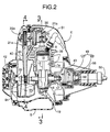
- FIG. 2 is a longitudinal side view of the above-mentioned four-cycle engine.
- FIG. 3 is a cross-sectional view at line 3-3 in FIG. 2.
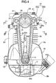
- FIG. 4 is a cross-sectional view at line 4-4 in FIG. 2.
- FIG. 5 is a magnified view of an essential part of FIG. 2.
- FIG. 6 is an exploded view of an essential part of FIG. 5.
- FIG. 7 is a cross-sectional view at line 7-7 in FIG. 4.
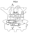
- FIG. 8 is a cross-sectional view at line 8-8 in FIG. 4.
- FIG. 9 is a cross-sectional view at line 9-9 in FIG. 8.
- FIG. 10 is a view from line 10-10 in FIG. 5 (bottom view of a head cover).
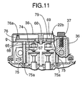
- FIG. 11 is a cross-sectional view at line 11-11 in FIG. 5.
- FIG. 12 is a diagram showing a lubrication route of the above-mentioned engine.
- Fig. 13 is a view corresponding to Fig. 4 in which the above-mentioned engine is in an upside down state.
- Fig. 14 is a view corresponding to Fig. 4 in which the above-mentioned engine is in a laid-sideways state.
-
- An embodiment of the present invention is explained below by reference to the appended drawings.
- As shown in FIG. 1, a handheld type four-cycle engine E is attached as a source of power to the drive section of, for example, a powered trimmer T. Since the powered trimmer T is used in a manner in which a cutter C is positioned so as to face in various directions according to the operational conditions, the engine E is also tilted to a large extent or turned upside-down as a result and the operational position is changeable.
- Firstly, the external structure of the handheld type four-cycle engine E is explained by reference to FIGS. 2 and 3.
- Attached to the front and back of an engine
main body 1 of the above-mentioned handheld type four-cycle engine E are acarburetor 2 and anexhaust muffler 3 respectively, and anair cleaner 4 is attached to the inlet of thecarburetor 2. Afuel tank 5 made of a synthetic resin is mounted on the lower face of the enginemain body 1. Opposite ends of acrankshaft 13 project outside the enginemain body 1 and anoil tank 40 adjoining one side of the enginemain body 1, and arecoil type starter 42 that can be operatively connected to a drivenmember 84 that is fixed to one end of thecrankshaft 13 is mounted on the outside face of theoil tank 40. - Fixed to the other end of the
crankshaft 13 is a coolingfan 43 that also serves as a flywheel. A plurality of fitting bosses 46 (one thereof is shown in FIG. 2) are formed on the outside face of the coolingfan 43, and acentrifugal shoe 47 is axially supported on each of thefitting bosses 46 in a swingable manner. Thesecentrifugal shoes 47, together with aclutch drum 48 fixed to adrive shaft 50 which will be described below, form a centrifugal clutch 49 and when the rotational rate of thecrankshaft 13 exceeds a predetermined value thecentrifugal shoes 47 are pressed onto the inner periphery of theclutch drum 48 due to the centrifugal force of theshoes 47, thereby transmitting the output torque of thecrankshaft 13 to thedrive shaft 50. The coolingfan 43 has a larger diameter than that of thecentrifugal clutch 49. - An
engine cover 51 covering the enginemain body 1 and its attachments except thefuel tank 5 is fixed at appropriate positions to the enginemain body 1, and a coolingair inlet 19 is provided between theengine cover 51 and thefuel tank 5. Rotation of the coolingfan 43 therefore takes in outside air through the coolingair inlet 19 and supplies it for cooling each part of the engine E. - Fixed to the
engine cover 51 is afrustoconical bearing holder 58 that is arranged coaxially with thecrankshaft 13, and the bearingholder 58 supports, via abearing 59, thedrive shaft 50 that rotates the cutter C. - Since the
oil tank 40 and thestarter 42 are arranged on one side of the enginemain body 1 and the coolingfan 43 and the centrifugal clutch 49 are arranged on the other side thereof, the weight balance of the engine E in the right and left directions is improved and the center of gravity of the engine E can be made closer to the central part of the enginemain body 1, thereby enhancing the handling performance of the engine E. - Furthermore, since the cooling
fan 43 which has a larger diameter than that of thecentrifugal shoe 47 is fixed to thecrankshaft 13 between the enginemain body 1 and thecentrifugal shoe 47, it is possible to minimize any increase in the dimensions of the engine E due to the coolingfan 43. - The structures of the engine
main body 1 and theoil tank 40 are now explained below by reference to FIGS. 2 to 6 and 10 and 11. - In FIGS. 2 to 5 the engine
main body 1 includes acrankcase 6 having a crankchamber 6a, acylinder block 7 having onecylinder bore 7a, and acylinder head 8 having acombustion chamber 8a and intake andexhaust ports combustion chamber 8a, and a large number ofcooling fins 38 are formed on the outer peripheries of thecylinder block 7 and thecylinder head 8. - The
crankshaft 13 housed in thecrank chamber 6a is supported in the left and right side walls of thecrankcase 6 viaball bearings 14 and 14'. In this case, the left-hand ball bearing 14 is equipped with a seal, and anoil seal 17 is provided so as to adjoin the outside of the right-hand ball bearing 14'. Apiston 15 fitted in thecylinder bore 7a is connected to thecrankshaft 13 via a connectingrod 16 in a conventional and general manner. - The
oil tank 40 is provided so as to be integrally formed with the left-hand wall of thecrankcase 6 and is arranged so that the end of thecrankshaft 13 on the sealedball bearing 14 side runs through theoil tank 40. Anoil seal 39 through which thecrankshaft 13 runs is fitted in the outside wall of theoil tank 40. - A
belt guide tube 86 having a flattened cross-section is provided integrally with the roof of theoil tank 40, thebelt guide tube 86 running vertically through the roof of theoil tank 40 and having open upper and lower ends. The lower end of thebelt guide tube 86 extends toward the vicinity of thecrankshaft 13 within theoil tank 40, and the upper end is provided integrally with thecylinder head 8 so as to share a dividingwall 85 with thecylinder head 8. A continuous ring-shapedsealing bead 87 is formed around the periphery of the upper end of thebelt guide tube 86 and thecylinder head 8, and the dividingwall 85 projects above the sealingbead 87. - As shown in FIGS. 6, 10 and 11, a ring-shaped
sealing channel 88a corresponding to the above-mentionedsealing bead 87 is formed in the lower end face of ahead cover 36, and alinear sealing channel 88b providing communication between opposite sides of the ring-shapedchannel 88a is formed in the inner face of thecover 36. A ring-shapedpacking 89a is fitted in the ring-shapedsealing channel 88a, and alinear packing 89b formed integrally with the ring-shapedpacking 89a is fitted in thelinear sealing channel 88b. Thehead cover 36 is joined to thecylinder head 8 by means of abolt 37 so that the sealingbead 87 and the dividingwall 85 are pressed into contact with the ring-shapedpacking 89a and thelinear packing 89b respectively. - The
belt guide tube 86 and one half of thehead cover 36 define a firstvalve operation chamber 21 a, thecylinder head 8 and the other half of thehead cover 36 define a secondvalve operation chamber 21b, and the twovalve operation chambers dividing wall 85. - Referring again to FIGS. 2 to 5, the engine
main body 1 and theoil tank 40 are divided into an upper block Ba and a lower block Bb on a plane that includes the axis of thecrankshaft 13 and is perpendicular to the axis of thecylinder bore 7a. That is to say, the upper block Ba integrally includes the upper half of thecrankcase 6, thecylinder block 7, thecylinder head 8, the upper half of theoil tank 40 and thebelt guide tube 86. The lower block Bb integrally includes the lower half of thecrankcase 6 and the lower half of theoil tank 40. These upper and lower blocks Ba and Bb are cast individually, and joined to each other by means of a plurality of bolts 12 (see FIG. 4) after each part has been machined. - Provided in the
cylinder head 8 so as to be parallel to the axis of thecylinder bore 7a are anintake valve 18i and anexhaust valve 18e for opening and closing theintake port 9 and theexhaust port 10 respectively, and aspark plug 20 is screwed into thecylinder head 8 so that the electrodes thereof are close to the central area of thecombustion chamber 8a. - A
valve operation mechanism 22 for opening and closing the above-mentionedintake valve 18i andexhaust valve 18e is explained below by reference to FIGS. 3 to 7. - The
valve operation mechanism 22 includes atiming transmission 22a, which runs from the interior of theoil tank 40 to the firstvalve operation chamber 21a, and acam system 22b, which runs from the firstvalve operation chamber 21a to the secondvalve operation chamber 21b. - The
timing transmission 22a includes adrive pulley 23 fixed to thecrankshaft 13 within theoil tank 40, a drivenpulley 24 rotatably supported in the upper part of thebelt guide tube 86, and atiming belt 25 wrapped around these drive and drivenpulleys pulley 24 on the dividingwall 85 side is joined integrally to acam 26 forming part of thecam system 22b. The drive and drivenpulleys drive pulley 23 drives the drivenpulley 24 via thebelt 25 with a reduction ratio of 1/2. - A
support wall 27 is formed integrally with the outside wall of thebelt guide tube 86, thesupport wall 27 rising inside the ring-shapedsealing bead 87 and being in contact with or in the vicinity of the inner face of thehead cover 36. A throughhole 28a and a bottomedhole 28b are provided in thesupport wall 27 and the dividingwall 85 respectively. Opposite ends of asupport shaft 29 are rotatably supported by the throughhole 28a and the bottomedhole 28b, and the above-mentioned drivenpulley 24 and thecam 26 are rotatably supported on the middle part of thesupport shaft 29. Thesupport shaft 29 is inserted from the throughhole 28a into ashaft hole 35 of the drivenpulley 24 and thecam 26 and the bottomedhole 28b before thehead cover 36 is attached. By joining thehead cover 36 to thecylinder head 8 and thebelt guide tube 86 subsequent to the insertion, the inner face of thehead cover 36 sits opposite the outer end of thesupport shaft 29 thereby preventing theshaft 29 from falling out. - Formed integrally with the dividing
wall 85 on the secondvalve operation chamber 21b side are a pair of bearingbosses support shaft 29. Thecam system 22b includes the above-mentionedcam 26, anintake rocker shaft 31i and anexhaust rocker shaft 31e rotatably supported in the above-mentionedbearing bosses intake cam follower 32i and anexhaust cam follower 32e fixed to one end of therocker shafts valve operation chamber 21a, the extremity of each of theintake cam follower 32i and theexhaust cam follower 32e being in sliding contact with the lower face of thecam 26, anintake rocker arm 33i and anexhaust rocker arm 33e fixed to the other end of the intake andexhaust rocker shafts valve operation chamber 21 b, the extremity of each of theintake rocker arm 33i and theexhaust rocker arm 33e being in contact with the upper end of theintake valve 18i andexhaust valve 18e respectively, and anintake spring 34i and anexhaust spring 34e mounted on theintake valve 18i and theexhaust valve 18e respectively and forcing them in the closed direction. - When the
crankshaft 13 rotates, thedrive pulley 23 rotating together with thecrankshaft 13 rotates the drivenpulley 24 and thecam 26 via thebelt 25, thecam 26 then rocks the intake andexhaust cam followers exhaust rocker arms rocker shafts exhaust rocker arms exhaust valves exhaust springs - In the
timing transmission 22a, since the drivenpulley 24 and thecam 26 are rotatably supported by thesupport shaft 29 and thesupport shaft 29 is also rotatably supported in opposite side walls of the firstvalve operation chamber 21a, thesupport shaft 29 rotates due to frictional drag during rotation of the drivenpulley 24 and thecam 26, the difference in rotational rate between thesupport shaft 29 and the drivenpulley 24 and thecam 26 decreases and abrasion of the rotating and sliding areas can be suppressed, thus contributing to an improvement in the durability. - The lubrication system of the above-mentioned engine E is now explained by reference to FIGS. 3 to 12.
- As shown in FIGS. 4 and 5, the
oil tank 40 stores a predetermined amount of lubricating oil O poured in through anoil inlet 40a. Within theoil tank 40, a pair ofoil slingers drive pulley 23 in the axial direction are press-fitted, etc. onto thecrankshaft 13. Theseoil slingers oil slingers crankshaft 13 at least one of theoil slingers oil tank 40, thereby generating an oil mist regardless of the operational position of the engine E. In this case, the oil mist becomes attached to the part of thetiming transmission 22a that extends within theoil tank 40 from the firstvalve operation chamber 21a, or the oil mist enters the firstvalve operation chamber 21a, and thetiming transmission 22a can thus be lubricated directly, which provides one lubrication system. - Another lubrication system includes, as shown in FIGS. 3 to 5 and 12, a through
hole 55 provided in thecrankshaft 13 so as to provide communication between the interior of theoil tank 40 and thecrank chamber 6a, anoil feed pipe 60 disposed outside the enginemain body 1 so as to connect the lower part of thecrank chamber 6a to the lower part of the secondvalve operation chamber 21b, anoil recovery chamber 74 provided in thecylinder head 8 in order to draw up oil liquefied and resided in the secondvalve operation chamber 21 b, anoil return passage 78 formed between thecylinder head 8 and theoil tank 40 so as to provide communication between theoil recovery chamber 74 and theoil tank 40 via the firstvalve operation chamber 21a, and a one-way valve 61 provided in the lower part of thecrank chamber 6a and allowing the flow of oil mist only in the direction from thecrank chamber 6a to theoil feed pipe 60. - An
open end 55a of the above-mentioned throughhole 55 within theoil tank 40 is positioned in the central part or the vicinity thereof within theoil tank 40 so that theopen end 55a is always above the liquid level of the oil O within theoil tank 40 regardless of the operational position of the engine E.The drive pulley 23 and one of theoil slingers 56a are fixed to thecrankshaft 13 with theopen end 55a therebetween so that it is not blocked. - The above-mentioned one-way valve 61 (see FIG. 3) is formed from a reed valve in the illustrated embodiment; it closes when the pressure of the
crank chamber 6a becomes negative and opens when the pressure becomes positive accompanying the reciprocating motion of thepiston 15. - The lower end of the
oil feed pipe 60 is connected by fitting it onto alower connection pipe 62a projectingly provided on the outside face of the crankcase 6 (see FIG. 3) and the upper end of theoil feel pipe 60 is connected by fitting it onto anupper connection pipe 62b projectingly provided on the outside face of the cylinder head 8 (see FIGS. 4 and 8). The interior of theupper connection pipe 62b communicates on the one hand with the lower part of the secondvalve operation chamber 21b via a communicating passage 63 (see FIGS. 8 and 9) formed in thecylinder head 8 and having large dimensions, and on the other hand with theoil return passage 78 via an orifice-like bypass 64 (see FIG. 8). - As shown in FIGS. 5, 10 and 11, a
partition plate 65 defining abreather chamber 69 in the upper part within thehead cover 36 is fitted to the roof of thehead cover 36 by means of a plurality ofstays 66 and clips 67 fastened to thestays 66, thestays 66 being projectingly provided on the roof. Thebreather chamber 69 communicates on the one hand with the secondvalve operation chamber 21b via a communicatingpipe 68 and a gap g between the inner face of thehead cover 36 and thepartition plate 65, the communicatingpipe 68, which has large dimensions, being formed integrally with thepartition plate 65 and projecting toward the secondvalve operation chamber 21b, and on the other hand with the interior of the above-mentionedair cleaner 4 via abreather pipe 70. In the breather chamber 69 a mixture of oil and blowby gas is separated into gas and liquid, and a labyrinth wall 72 for promoting the gas-liquid separation is projectingly provided on the inner face of the roof of thehead cover 36. - The upper surface of the
partition plate 65 is welded to a box-shapedpartition body 79, having one open face and being T-shaped in plan view, so as to define the above-mentionedoil recovery chamber 74 therebetween, theoil recovery chamber 74 therefore also being T-shaped. - Integral with the
partition plate 65 are projectingly provided two draw-uppipes 75, which respectively communicate with opposite ends of the lateral bar of the T-shapedoil recovery chamber 74. The extremity of each of the draw-uppipes 75 extends toward the vicinity of the base of the secondvalve operation chamber 21b, and an opening in the extremity of each of the draw-uppipes 75 forms anorifice 75a. - Integral with the upper wall of the
partition body 79 are projectingly provided three draw-uppipes 76, which communicate with three positions corresponding to the extremities of the lateral and vertical bars of the T-shape of theoil recovery chamber 74. Each of the extremities of these draw-uppipes 76 extends toward the vicinity of the roof of thebreather chamber 69, and an opening in the extremity of each of the draw-uppipes 76 forms anorifice 76a. - Furthermore, in the upper wall of the
partition body 79 is provided anorifice 80, providing communication between anindentation 79a in the upper face of thepartition body 79 and theoil recovery chamber 74. - Moreover, integral with the
partition plate 65 is projectingly provided onepipe 81 communicating with a region corresponding to the extremity of the vertical bar of the T-shape of theoil recovery chamber 74. The extremity of thepipe 81 is fitted into aninlet 78a of the above-mentionedoil return passage 78 via agrommet 82, theinlet 78a opening onto the base of the secondvalve operation chamber 21b. Theoil recovery chamber 74 is thereby connected to theoil return passage 78. The above-mentionedpipe 81 is placed close to an inner side face of the secondvalve operation chamber 21b, and anorifice 81a for drawing up oil is provided in the region close to the above-mentioned inner side face, theorifice 81a providing communication between the secondvalve operation chamber 21 b and the interior of thepipe 81. - Since the
breather chamber 69 communicates with the interior of theair cleaner 4 via thebreather pipe 70, the pressure of thebreather chamber 69 is maintained at substantially atmospheric pressure even during operation of the engine E, and the pressure of the secondvalve operation chamber 21b communicating with thebreather chamber 69 via the communicatingpipe 68, which has a low flow resistance, is substantially the same as that of thebreather chamber 69. - Since the
crank chamber 6a discharges only the positive pressure component of the pressure pulsations caused by the ascending and descending motion of thepiston 15 into theoil feed pipe 60 through the one-way valve 61 during operation of the engine E, the pressure of thecrank chamber 6a is negative on average, and since the secondvalve operation chamber 21b receiving the above-mentioned positive pressure communicates with thebreather chamber 69 via the communicatingpipe 68 having a small flow resistance, the pressure of the secondvalve operation chamber 21b is substantially the same as that of thebreather chamber 69. Since the negative pressure of thecrank chamber 6a is transmitted to theoil tank 40 via the throughhole 55 of thecrankshaft 13 and further to theoil recovery chamber 74 via theoil return passage 78, the pressure of theoil recovery chamber 74 is lower than those of the secondvalve operation chamber 21b and thebreather chamber 69, and the pressures of theoil tank 40 and the firstvalve operation chamber 21 a are lower than that of theoil recovery chamber 74. - As shown in FIG. 12, if the pressure of the
crank chamber 6a is denoted by Pc, the pressure of theoil tank 40 is denoted by Po, the pressure of the firstvalve operation chamber 21a is denoted by Pva, the pressure of the secondvalve operation chamber 21 b is denoted by Pvb, the pressure of theoil recovery chamber 74 is denoted by Ps, and the pressure of thebreather chamber 69 is denoted by Pb, the following relationship is therefore satisfied.
Pvb = Pb > Ps > Po = Pva > Pc - As a result, the pressure of the second
valve operation chamber 21b and thebreather chamber 69 is transferred to theoil recovery chamber 74 via the draw-uppipes orifice 80, further to theoil tank 40 via theoil return passage 78 and then to the crankchamber 6a. - During operation of the engine E, oil mist is generated by the
oil slingers oil tank 40, theoil slingers crankshaft 13. As hereinbefore described, the oil droplets so generated is splashed over the part of thetiming transmission 22a exposed within theoil tank 40 from thebelt guide tube 86, that is to say, thedrive pulley 23 and part of thetiming belt 25, or the oil droplets enter the firstvalve operation chamber 21a, and thetiming transmission 22a is thus lubricated directly. - The oil mist generated in the
oil tank 40 is drawn into thecrank chamber 6a via the throughhole 55 of thecrankshaft 13 along the direction of the above-mentioned pressure flow, thereby lubricating the area around thecrankshaft 13 and thepiston 15. When the pressure of thecrank chamber 6a becomes positive due to thepiston 15 descending, the one-way valve 61 opens and the above-mentioned oil mist together with the blowby gas generated in thecrank chamber 6a ascend through theoil feed pipe 60 and the communicatingpassage 63 and are supplied to the secondvalve operation chamber 21b, thereby lubricating each part of thecam system 22b within thechamber 21b, that is to say, the intake andexhaust rocker arms - In this case, a portion of the oil mist passing through the above-mentioned communicating
passage 63 is shunted to theoil return passage 78 via the orifice-like bypass 64. It is therefore possible to control the amount of oil mist supplied to the secondvalve operation chamber 21b by setting the flow resistance of thebypass 64 appropriately. - The oil mist and the blowby gas within the second
valve operation chamber 21b are separated into gas and liquid by expansion and collision with the labyrinth wall 72 while being transferred to thebreather chamber 69 through the communicatingpipe 68 and the gap g around thepartition plate 65, and the blowby gas is taken into the engine E via thebreather pipe 70 and theair cleaner 4 in that order during the intake stroke of the engine E. - When the engine E is in an upright state, since the oil liquefied in the
breather chamber 69 resides in theindentation 79a in the upper face of thepartition body 79 or flows down the communicatingpipe 68 or through the gap g and is resided on the base of the secondvalve operation chamber 21b, in that case the oil is drawn up by means of theorifice 80 or the draw-uppipe 75 provided in those places into theoil recovery chamber 74. When the engine E is in an upside down state, since the above-mentioned liquefied oil resides on the roof of thehead cover 36, in that case the oil is drawn up by means of the draw-uppipe 76 provided there into theoil recovery chamber 74. - The oil thus drawn up into the
oil recovery chamber 74 returns from thepipe 81 into theoil tank 40 via theoil return passage 78. In this case, when theoil return passage 78 communicates with theoil tank 40 via the firstvalve operation chamber 21a as in the illustrated embodiment, the oil discharged from theoil return passage 78 is splashed over thetiming transmission 22a, thereby advantageously lubricating it. - Since the roof of the
head cover 36 and thepartition plate 65 attached to the inner wall of thehead cover 36 define the above-mentionedbreather chamber 69 therebetween and the upper face of the above-mentionedpartition plate 65 and thepartition body 79 welded to thepartition plate 65 define the above-mentionedoil recovery chamber 74 therebetween, theoil recovery chamber 74 and thebreather chamber 69 can be provided in thehead cover 36 without splitting the roof of thehead cover 36. Moreover, since thebreather chamber 69 and theoil recovery chamber 74 are present within thehead cover 36, even if some oil leaks from either of thechambers valve operation chamber 21b without causing any problems, it is unnecessary to inspect the peripheries of the twochambers - Since the
partition body 79 can be welded to thepartition plate 65 before attaching thepartition plate 65 to thehead cover 36, theoil recovery chamber 74 can easily be formed using thepartition plate 65. - Furthermore, since the oil draw-up
pipes partition plate 65 and thepartition body 79 respectively, the oil draw-uppipes - When the engine E is in an upside down state as shown in FIG. 13, the oil O stored in the
oil tank 40 moves toward the roof of thetank 40, that is to say, the firstvalve operation chamber 21a side. Since the open end of the firstvalve operation chamber 21a within theoil tank 40 is set so as to be at a higher level than the liquid level of the stored oil O by means of thebelt guide tube 86, the stored oil O is prevented from entering the firstvalve operation chamber 21a, thereby preventing excess oil from being supplied to thetiming transmission 22a, and it is also possible to maintain a predetermined amount of oil within theoil tank 40, thus allowing theoil slingers - When the engine E is laid sideways during its operation as shown in FIG. 14, the stored oil O moves toward the side face of the
oil tank 40, and, in this case also, since the open end of the firstvalve operation chamber 21a within theoil tank 40 is set so as to be at a higher level than the liquid level of the stored oil O by means of thebelt guide tube 86, the stored oil O is prevented from entering the firstvalve operation chamber 21a and it is possible to prevent excess oil from being supplied to thetiming transmission 22a and also to maintain a predetermined amount of oil within theoil tank 40, thus allowing theoil slingers - The lubrication system for the
valve operation mechanism 22 can thus be divided into a system for lubricating part of thecam system 22b and thetiming transmission 22a within the firstvalve operation chamber 21a and theoil tank 40 with the oil scattered within theoil tank 40, and a system for lubricating the remainder of thecam system 22b within the secondvalve operation chamber 21b with the oil mist transferred to the secondvalve operation chamber 21b. The load put on each of the lubrication systems can thus be reduced and the entirevalve operation mechanism 22 can be lubricated thoroughly. Moreover, each part of the engine E can be lubricated reliably by the use of oil droplets and oil mist regardless of the operational position of the engine E. - Since the oil mist generated within the
oil tank 40 is returned by utilizing the pressure pulsations within thecrank chamber 6a and the one-way transfer function of the one-way valve 61, it is unnecessary to employ a special oil pump for circulating the oil mist and the structure can be simplified. - Furthermore, not only the
oil tank 40 but also theoil feed pipe 60 providing communication between thecrank chamber 6a and the secondvalve operation chamber 21b are disposed outside the enginemain body 1, which does not prevent making the enginemain body 1 thinner and more compact, greatly contributing to reduction in the weight of the engine E. In particular, since the externally placedoil feed pipe 60 is little influenced by the heat of the enginemain body 1 and easily releases its heat, cooling of the oil mist passing through theoil feed pipe 60 can be promoted. - Furthermore, since the
oil tank 40 is placed on one side of the exterior of the enginemain body 1, the total height of the engine E can be greatly reduced, and since part of thetiming transmission 22a is housed in theoil tank 40, any increase in the width of the engine E can be minimized, thus making the engine E more compact. - The number of oil draw-up
pipes orifices partition body 79 can be welded to the lower face of thepartition plate 65, thereby forming theoil recovery chamber 74 below thepartition plate 65. In this case, the oil draw-uppipe 75 is formed integrally with thepartition body 79 and the oil draw-uppipe 76 is formed integrally with thepartition plate 65. - Moreover, instead of the one
way valve 61, a rotary valve can be provided, the rotary valve being operable in association with thecrankshaft 13 and operating so as to open theoil feed pipe 60 when thepiston 15 descends and block theoil feed pipe 60 when thepiston 15 ascends. - The present invention is not limited to the above-mentioned embodiment and can be modified in a variety of ways without departing from the spirit and scope of the invention.
- An engine head cover structure has a head cover joined to the upper end of a cylinder head so as to define a valve operation chamber therebetween. The head cover includes therein an oil recovery chamber to which oil resided in the valve operation chamber is recovered by suction and a breather chamber that removes blowby gas from the valve operation chamber being provided in the head cover. The breather chamber is defined between a partition plate mounted on an inner wall of the head cover via clips and a surface of the roof of the head cover, and the oil recovery chamber is defined between the partition plate and a partition body welded thereto. It is thus possible to form the oil recovery chamber and the breather chamber without splitting the roof of the head cover, thereby making inspection of the joint for oil tightness unnecessary.
Claims (3)
- An engine head cover structure having a head cover joined to the upper end of a cylinder head so as to define a valve operation chamber therebetween, the head cover including therein an oil recovery chamber to which oil resided in the valve operation chamber is recovered by suction and a breather chamber that removes blowby gas from the valve operation chamber,
wherein the breather chamber is defined between a partition plate mounted on an inner wall of the head cover and a surface of the roof of the head cover, and the oil recovery chamber is formed integrally with the partition plate. - The engine head cover structure according to Claim 1, wherein the oil recovery chamber is defined between the surface of one side of the partition plate and a partition body welded thereto.
- The engine head cover structure according to Claim 2, wherein a first oil draw-up pipe that opens in the vicinity of the base of the valve operation chamber while communicating with the oil recovery chamber is formed integrally with one of the partition plate and the partition body, and a second oil draw-up pipe that opens in the vicinity of the roof of the head cover while communicating with the oil recovery chamber is formed integrally with the other one of the partition plate and the partition body.
Applications Claiming Priority (2)
| Application Number | Priority Date | Filing Date | Title |
|---|---|---|---|
| JP2000329935A JP3894723B2 (en) | 2000-10-30 | 2000-10-30 | Engine head cover structure |
| JP2000329935 | 2000-10-30 |
Publications (2)
| Publication Number | Publication Date |
|---|---|
| EP1201887A1 true EP1201887A1 (en) | 2002-05-02 |
| EP1201887B1 EP1201887B1 (en) | 2005-06-22 |
Family
ID=18806536
Family Applications (1)
| Application Number | Title | Priority Date | Filing Date |
|---|---|---|---|
| EP01125920A Expired - Lifetime EP1201887B1 (en) | 2000-10-30 | 2001-10-30 | Engine head cover structure |
Country Status (8)
| Country | Link |
|---|---|
| US (1) | US6561154B2 (en) |
| EP (1) | EP1201887B1 (en) |
| JP (1) | JP3894723B2 (en) |
| KR (1) | KR100407019B1 (en) |
| CN (1) | CN1189647C (en) |
| CA (1) | CA2360457C (en) |
| DE (1) | DE60111603T2 (en) |
| TW (1) | TW542872B (en) |
Cited By (2)
| Publication number | Priority date | Publication date | Assignee | Title |
|---|---|---|---|---|
| EP1288454A1 (en) * | 2001-08-27 | 2003-03-05 | Honda Giken Kogyo Kabushiki Kaisha | System for lubricating valve-operating mechanism in engine |
| CN110344963A (en) * | 2019-07-20 | 2019-10-18 | 徐海燕 | A kind of floating type mounting structure of valve mechanism cover |
Families Citing this family (11)
| Publication number | Priority date | Publication date | Assignee | Title |
|---|---|---|---|---|
| JP2003007727A (en) * | 2001-06-22 | 2003-01-10 | Sanyo Electric Co Ltd | Compound semiconductor device |
| JP4018944B2 (en) * | 2002-07-08 | 2007-12-05 | 富士重工業株式会社 | Blowby gas recirculation system and blowby gas recirculation method |
| JP4032878B2 (en) * | 2002-08-23 | 2008-01-16 | 三菱ふそうトラック・バス株式会社 | Breather device for internal combustion engine |
| US6672294B1 (en) * | 2003-01-09 | 2004-01-06 | Thomas A. Pirone | Rocker box oil separation vent system |
| CN103016188A (en) * | 2011-09-23 | 2013-04-03 | 江苏林海动力机械集团公司 | Cylinder cover assembly structure for four-stroke engine |
| US20140123931A1 (en) * | 2012-11-03 | 2014-05-08 | Nagesh Siddabasappa Mavinahally | Half crank engine |
| KR101490924B1 (en) * | 2013-06-27 | 2015-02-06 | 현대자동차 주식회사 | Timing belt system for vehicle |
| KR101490948B1 (en) * | 2013-09-09 | 2015-02-12 | 현대자동차 주식회사 | Damper pully assembly of vehicle |
| CN106903550B (en) * | 2015-12-22 | 2018-11-16 | 北京新思维汇德精密磨床有限责任公司 | It is a kind of without pump oil return mechanism |
| US10533471B2 (en) * | 2016-06-16 | 2020-01-14 | Honda Motor Co., Ltd. | Internal combustion engine |
| CN114450475B (en) * | 2019-10-09 | 2023-12-05 | 本田技研工业株式会社 | Cylinder head cover structure, engine and operation equipment |
Citations (4)
| Publication number | Priority date | Publication date | Assignee | Title |
|---|---|---|---|---|
| JPH08260936A (en) * | 1995-03-27 | 1996-10-08 | Kubota Corp | Engine breather device |
| EP0911496A1 (en) * | 1997-10-22 | 1999-04-28 | Honda Giken Kogyo Kabushiki Kaisha | Breather device for engine |
| FR2789125A1 (en) * | 1999-01-29 | 2000-08-04 | Renault | DEVICE FOR RESPIRATING THE CRANKCASE GASES OF AN ENGINE |
| JP2000257412A (en) * | 1999-03-03 | 2000-09-19 | Honda Motor Co Ltd | Lubrication structure for valve drive of internal combustion engine |
Family Cites Families (8)
| Publication number | Priority date | Publication date | Assignee | Title |
|---|---|---|---|---|
| JPS6179813A (en) * | 1984-09-26 | 1986-04-23 | Toyota Motor Corp | Oil separating device for blow-by gas |
| US6029638A (en) * | 1997-11-07 | 2000-02-29 | Honda Giken Kogyo Kabushiki Kaisha | Internal combustion engine with dry sump lubricating system |
| JP3805505B2 (en) * | 1997-11-19 | 2006-08-02 | 本田技研工業株式会社 | Breather structure of engine unit |
| JP3323434B2 (en) * | 1998-01-23 | 2002-09-09 | 株式会社クボタ | Engine with breather device |
| JP2000073729A (en) * | 1998-09-01 | 2000-03-07 | Kioritz Corp | 4-cycle internal combustion engine |
| US6530355B2 (en) * | 2000-07-12 | 2003-03-11 | Honda Giken Kogyo Kabushiki Kaisha | 4-cycle engine |
| JP2002138898A (en) * | 2000-11-01 | 2002-05-17 | Honda Motor Co Ltd | Engine valve train |
| US6412478B1 (en) * | 2001-01-02 | 2002-07-02 | Generac Power Systems, Inc. | Breather for internal combustion engine |
-
2000
- 2000-10-30 JP JP2000329935A patent/JP3894723B2/en not_active Expired - Fee Related
-
2001
- 2001-10-29 US US09/984,167 patent/US6561154B2/en not_active Expired - Lifetime
- 2001-10-29 CA CA002360457A patent/CA2360457C/en not_active Expired - Fee Related
- 2001-10-29 TW TW090126780A patent/TW542872B/en not_active IP Right Cessation
- 2001-10-30 KR KR10-2001-0066958A patent/KR100407019B1/en not_active Expired - Fee Related
- 2001-10-30 CN CNB011338814A patent/CN1189647C/en not_active Expired - Lifetime
- 2001-10-30 DE DE60111603T patent/DE60111603T2/en not_active Expired - Lifetime
- 2001-10-30 EP EP01125920A patent/EP1201887B1/en not_active Expired - Lifetime
Patent Citations (5)
| Publication number | Priority date | Publication date | Assignee | Title |
|---|---|---|---|---|
| JPH08260936A (en) * | 1995-03-27 | 1996-10-08 | Kubota Corp | Engine breather device |
| EP0911496A1 (en) * | 1997-10-22 | 1999-04-28 | Honda Giken Kogyo Kabushiki Kaisha | Breather device for engine |
| JPH11125107A (en) | 1997-10-22 | 1999-05-11 | Honda Motor Co Ltd | Engine breather device |
| FR2789125A1 (en) * | 1999-01-29 | 2000-08-04 | Renault | DEVICE FOR RESPIRATING THE CRANKCASE GASES OF AN ENGINE |
| JP2000257412A (en) * | 1999-03-03 | 2000-09-19 | Honda Motor Co Ltd | Lubrication structure for valve drive of internal combustion engine |
Non-Patent Citations (2)
| Title |
|---|
| PATENT ABSTRACTS OF JAPAN vol. 1997, no. 02 28 February 1997 (1997-02-28) * |
| PATENT ABSTRACTS OF JAPAN vol. 2000, no. 12 3 January 2001 (2001-01-03) * |
Cited By (4)
| Publication number | Priority date | Publication date | Assignee | Title |
|---|---|---|---|---|
| EP1288454A1 (en) * | 2001-08-27 | 2003-03-05 | Honda Giken Kogyo Kabushiki Kaisha | System for lubricating valve-operating mechanism in engine |
| US6715461B2 (en) | 2001-08-27 | 2004-04-06 | Honda Giken Kogyo Kabushiki Kaisha | System for lubricating valve-operating mechanism in engine |
| CN110344963A (en) * | 2019-07-20 | 2019-10-18 | 徐海燕 | A kind of floating type mounting structure of valve mechanism cover |
| CN110344963B (en) * | 2019-07-20 | 2020-10-27 | 温州瑞明工业股份有限公司 | Floating mounting structure of cylinder head cover |
Also Published As
| Publication number | Publication date |
|---|---|
| EP1201887B1 (en) | 2005-06-22 |
| DE60111603D1 (en) | 2005-07-28 |
| CA2360457A1 (en) | 2002-04-30 |
| DE60111603T2 (en) | 2005-11-03 |
| KR100407019B1 (en) | 2003-11-28 |
| US6561154B2 (en) | 2003-05-13 |
| JP3894723B2 (en) | 2007-03-22 |
| KR20020034901A (en) | 2002-05-09 |
| CN1356453A (en) | 2002-07-03 |
| CA2360457C (en) | 2004-11-30 |
| TW542872B (en) | 2003-07-21 |
| JP2002129931A (en) | 2002-05-09 |
| CN1189647C (en) | 2005-02-16 |
| US20020066433A1 (en) | 2002-06-06 |
Similar Documents
| Publication | Publication Date | Title |
|---|---|---|
| US6705263B2 (en) | Handheld type four-cycle engine | |
| CA2360457C (en) | Engine head cover structure | |
| US6484679B2 (en) | Engine valve operation mechanism | |
| US6715461B2 (en) | System for lubricating valve-operating mechanism in engine | |
| EP1172540B1 (en) | Seal structure in engine body | |
| KR100428497B1 (en) | Valve-operating mechanism in 4-cycle engine | |
| EP1201882B1 (en) | Engine valve operation mechanism | |
| JP4371563B2 (en) | Engine valve mechanism | |
| JP4394819B2 (en) | Lubricating device for timing gears in handheld engines | |
| JP3881830B2 (en) | Valve mechanism of handheld four-cycle engine | |
| JP4015389B2 (en) | Engine valve mechanism lubrication system | |
| JP3881831B2 (en) | Four cycle engine | |
| JP2003090205A (en) | Engine breather device | |
| JP2002089281A (en) | Four cycle engine |
Legal Events
| Date | Code | Title | Description |
|---|---|---|---|
| PUAI | Public reference made under article 153(3) epc to a published international application that has entered the european phase |
Free format text: ORIGINAL CODE: 0009012 |
|
| AK | Designated contracting states |
Kind code of ref document: A1 Designated state(s): AT BE CH CY DE DK ES FI FR GB GR IE IT LI LU MC NL PT SE Kind code of ref document: A1 Designated state(s): DE FR GB |
|
| AX | Request for extension of the european patent |
Free format text: AL;LT;LV;MK;RO;SI |
|
| 17P | Request for examination filed |
Effective date: 20020607 |
|
| AKX | Designation fees paid |
Free format text: DE FR GB |
|
| GRAP | Despatch of communication of intention to grant a patent |
Free format text: ORIGINAL CODE: EPIDOSNIGR1 |
|
| GRAS | Grant fee paid |
Free format text: ORIGINAL CODE: EPIDOSNIGR3 |
|
| GRAA | (expected) grant |
Free format text: ORIGINAL CODE: 0009210 |
|
| AK | Designated contracting states |
Kind code of ref document: B1 Designated state(s): DE FR GB |
|
| REG | Reference to a national code |
Ref country code: GB Ref legal event code: FG4D |
|
| REF | Corresponds to: |
Ref document number: 60111603 Country of ref document: DE Date of ref document: 20050728 Kind code of ref document: P |
|
| ET | Fr: translation filed | ||
| PLBE | No opposition filed within time limit |
Free format text: ORIGINAL CODE: 0009261 |
|
| STAA | Information on the status of an ep patent application or granted ep patent |
Free format text: STATUS: NO OPPOSITION FILED WITHIN TIME LIMIT |
|
| 26N | No opposition filed |
Effective date: 20060323 |
|
| REG | Reference to a national code |
Ref country code: FR Ref legal event code: PLFP Year of fee payment: 16 |
|
| REG | Reference to a national code |
Ref country code: FR Ref legal event code: PLFP Year of fee payment: 17 |
|
| REG | Reference to a national code |
Ref country code: FR Ref legal event code: PLFP Year of fee payment: 18 |
|
| PGFP | Annual fee paid to national office [announced via postgrant information from national office to epo] |
Ref country code: FR Payment date: 20180913 Year of fee payment: 18 |
|
| PGFP | Annual fee paid to national office [announced via postgrant information from national office to epo] |
Ref country code: DE Payment date: 20181016 Year of fee payment: 18 |
|
| PGFP | Annual fee paid to national office [announced via postgrant information from national office to epo] |
Ref country code: GB Payment date: 20181024 Year of fee payment: 18 |
|
| REG | Reference to a national code |
Ref country code: DE Ref legal event code: R119 Ref document number: 60111603 Country of ref document: DE |
|
| PG25 | Lapsed in a contracting state [announced via postgrant information from national office to epo] |
Ref country code: DE Free format text: LAPSE BECAUSE OF NON-PAYMENT OF DUE FEES Effective date: 20200501 |
|
| GBPC | Gb: european patent ceased through non-payment of renewal fee |
Effective date: 20191030 |
|
| PG25 | Lapsed in a contracting state [announced via postgrant information from national office to epo] |
Ref country code: FR Free format text: LAPSE BECAUSE OF NON-PAYMENT OF DUE FEES Effective date: 20191031 Ref country code: GB Free format text: LAPSE BECAUSE OF NON-PAYMENT OF DUE FEES Effective date: 20191030 |