EP1201873B1 - PDC-Bohrkopf mit spannungsvermindernder Nut - Google Patents
PDC-Bohrkopf mit spannungsvermindernder Nut Download PDFInfo
- Publication number
- EP1201873B1 EP1201873B1 EP01402782A EP01402782A EP1201873B1 EP 1201873 B1 EP1201873 B1 EP 1201873B1 EP 01402782 A EP01402782 A EP 01402782A EP 01402782 A EP01402782 A EP 01402782A EP 1201873 B1 EP1201873 B1 EP 1201873B1
- Authority
- EP
- European Patent Office
- Prior art keywords
- bit body
- cutting element
- relief groove
- displacement
- drill bit
- Prior art date
- Legal status (The legal status is an assumption and is not a legal conclusion. Google has not performed a legal analysis and makes no representation as to the accuracy of the status listed.)
- Expired - Lifetime
Links
- 238000005520 cutting process Methods 0.000 claims description 42
- 238000006073 displacement reaction Methods 0.000 claims description 35
- 229910003460 diamond Inorganic materials 0.000 claims description 33
- 239000010432 diamond Substances 0.000 claims description 33
- 238000000034 method Methods 0.000 claims description 13
- 239000000758 substrate Substances 0.000 claims description 12
- UONOETXJSWQNOL-UHFFFAOYSA-N tungsten carbide Chemical compound [W+]#[C-] UONOETXJSWQNOL-UHFFFAOYSA-N 0.000 claims description 11
- 239000000956 alloy Substances 0.000 claims description 9
- 229910045601 alloy Inorganic materials 0.000 claims description 9
- 239000011230 binding agent Substances 0.000 claims description 7
- 239000000463 material Substances 0.000 claims description 5
- 238000005553 drilling Methods 0.000 description 5
- 238000000465 moulding Methods 0.000 description 5
- OKTJSMMVPCPJKN-UHFFFAOYSA-N Carbon Chemical compound [C] OKTJSMMVPCPJKN-UHFFFAOYSA-N 0.000 description 2
- 238000005266 casting Methods 0.000 description 2
- 239000012530 fluid Substances 0.000 description 2
- 229910002804 graphite Inorganic materials 0.000 description 2
- 239000010439 graphite Substances 0.000 description 2
- 238000003754 machining Methods 0.000 description 2
- 239000011159 matrix material Substances 0.000 description 2
- 229910000831 Steel Inorganic materials 0.000 description 1
- 230000015572 biosynthetic process Effects 0.000 description 1
- 238000005219 brazing Methods 0.000 description 1
- 230000007812 deficiency Effects 0.000 description 1
- 230000003628 erosive effect Effects 0.000 description 1
- 238000005242 forging Methods 0.000 description 1
- 238000005755 formation reaction Methods 0.000 description 1
- 239000003779 heat-resistant material Substances 0.000 description 1
- 230000008595 infiltration Effects 0.000 description 1
- 238000001764 infiltration Methods 0.000 description 1
- 238000003780 insertion Methods 0.000 description 1
- 230000037431 insertion Effects 0.000 description 1
- 238000003825 pressing Methods 0.000 description 1
- 238000000926 separation method Methods 0.000 description 1
- 238000007493 shaping process Methods 0.000 description 1
- 239000010959 steel Substances 0.000 description 1
- 230000007704 transition Effects 0.000 description 1
Images


Classifications
-
- E—FIXED CONSTRUCTIONS
- E21—EARTH DRILLING; MINING
- E21B—EARTH DRILLING, e.g. DEEP DRILLING; OBTAINING OIL, GAS, WATER, SOLUBLE OR MELTABLE MATERIALS OR A SLURRY OF MINERALS FROM WELLS
- E21B10/00—Drill bits
- E21B10/46—Drill bits characterised by wear resisting parts, e.g. diamond inserts
- E21B10/54—Drill bits characterised by wear resisting parts, e.g. diamond inserts the bit being of the rotary drag type, e.g. fork-type bits
- E21B10/55—Drill bits characterised by wear resisting parts, e.g. diamond inserts the bit being of the rotary drag type, e.g. fork-type bits with preformed cutting elements
Definitions
- the invention is related to the field of fixed cutter bits used to drill wellbores through earth formations. More specifically, the invention is related to structures for, and methods for making, alloy bodies for polycrystalline diamond compact cutter drill bits.
- PDC bits Fixed cutter drill bits known in the art include polycrystalline diamond compact (PDC) bits.
- the typical PDC bit includes a bit body which is made from powdered tungsten carbide infiltrated with a binder alloy within a suitable mold form.
- the particular materials used to form PDC bit bodies are selected to provide adequate toughness, while providing good resistance to abrasive and erosive wear.
- the cutting elements used on these bits are typically formed from a cylindrical tungsten carbide "blank" or substrate.
- a diamond “table” made from various forms of natural and/or synthetic diamond is affixed to the substrate. The substrate is then generally brazed or otherwise bonded to the bit body in a selected position on the surface of the body.
- PDC bit bodies in order to be resistant to wear, are very hard and are therefore difficult to machine. Therefore, the selected positions at which the PDC cutting elements are to be affixed to the bit body are typically formed substantially to their final shape during the bit body molding process.
- a common practice in molding PDC bit bodies is to include in the mold at each of the to-be-formed cutter mounting positions, a shaping element called a "displacement".
- a displacement is generally a small cylinder made from graphite or other heat resistant material which is affixed to the inside of the mold at each of the places where a PDC cutter is to be located on the finished drill bit. The displacement forms the shape of the cutter mounting positions during the bit body molding process. See, for example, U.S. patent no. 5,662,183 issued to Fang for a description of the infiltration molding process using displacements.
- Prior art document US-A-5.373.908 discloses a cutting structure for use in a rotary drill bit which is configured to provide relief from stress forces concentrated at the interface between a segmented PDC cutting element and the carrier element to which it is bonded.
- PDC bits known in the art have been subject to fracture failure of the diamond table, and/or separation of the diamond table from the substrate during drilling operations.
- One reason for such failures is compressive contact between the exterior of the diamond table and the proximate surface of the bit body under drilling loading conditions.
- One solution to this problem known in the art is to mount the cutting elements so that substantially all of the thickness of the diamond table is projected outward past the surface of the bit body. While this solution does reduce the incidence of diamond table failure, having the diamond tables extend outwardly past the bit body can cause erratic or turbulent flow of drilling fluid past the cutting elements on the bit. This turbulent flow has been known to cause the cutter mounting to erode, and to cause the bonding between the cutters and the bit body to fail, among other deficiencies in this type of PDC bit configuration. It is preferable to have the PDC cutters mounted so that they are substantially flush with the outer surface of the mounting position on the bit body.
- One aspect is a method for forming a drill bit body which comprises infiltrating powdered tungsten carbide with a binder alloy in a mold.
- the mold has therein at least one displacement adapted to form a mounting pad for a cutting element.
- the displacement comprises a substantially cylindrical body having a diameter selected to substantially conform to a radius of the cutting element and a projection adapted to form a relief groove under a position of a diamond table forming part of the cutting element when the cutting element is mounted on the pad.
- the width of the relief groove is selected so that the relief groove extends back from an outer surface of the bit body at least about 40 percent of that portion of a thickness of the diamond table which does not extend past the outer surface.
- a drill bit body comprising a main body having at least one blade formed therein, and at least one cutting element mounting pad formed on the at least one blade.
- the mounting pad is adapted to receive therein a substrate of a cutting element.
- the mounting pad has a relief groove therein under a position of a diamond table in the cutting element when the cutting element is mounted on the pad. The width of the relief groove is selected so that the relief groove extends back from an outer surface of the blade at least about 40 percent of that portion of a thickness of the diamond table which does not extend past the outer surface.
- a matrix drill bit body for a fixed cutter bit can be made from powdered tungsten carbide infiltrated with a binder alloy in a suitably shaped mold or other form. See, for example, U.S. patent no. 5,662,183 issued to Fang.
- the bit body forming process described in the Fang '183 patent includes insertion of plugs, called “displacements,” in locations about the bit body on which cutting elements are to be mounted to the finished bit body.
- the locations at which cutting elements are to be mounted are referred to for convenience herein as "mounting pads”.
- displacements are inserted into the mold during the body forming process to produce mounting pads for the cutting elements.
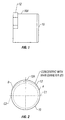
- An example of a displacement according to one aspect of the invention is shown in Figure 1.
- the displacement 10 in this embodiment is a substantially cylindrical body having a selected length indicated by L, a diameter indicated by D and on one end, a projection 12 having a selected width W.
- the length L and diameter D are selected to provide a mounting pad (not shown in Figure 1) on the finished bit body (not shown in Figure 1) having dimensions suitable to mount a selected cutting element (not shown in Figure 1).
- the cutting element (not shown in Figure 1) affixed to the mounting pad will be a polycrystalline diamond compact insert.
- the projection 12 in this embodiment has a substantially cylindrical shape and extends laterally past the exterior surface 10A of the main body of the displacement 10 by about 0.025 inches (0.63 mm) in this embodiment.
- the displacement 10 is affixed to the mold (not shown in Figure 1) so that the mounting pad is formed to have a recess or relief groove (not shown in Figure 1) positioned under a diamond table forming part of the cutting element affixed to the mounting pad. The position of the relief groove and diamond table will be further explained.
- the example displacement is shown in an end view in Figure 2, where the shape and lateral extent of the projection 12 can be seen.
- the projection 12 has a primary surface 12A which extends laterally from the surface (10A in Figure 1) of the displacement by about 0.025 inches (0.63 mm) and is substantially concentric with the surface (10A in Figure 1) of the displacement 10 between points A and B.
- Transition surfaces, formed between endpoint A and point C1, and endpoint B and point C2 on the circumference of the displacement 10 can be formed to gradually adjust the radius of the exterior surface of the projection 12 to match the radius of the main surface 10A of the displacement 10.
- points C1 and C2 will be spaced about 180 degrees apart, so that the relief groove formed in the mounting pad will extend about 180 degrees. Other angular spacings of points C1 and C2, and endpoints A and B will also work with the invention, however.
- the displacement 10 may be made from graphite or any other suitable material used for molding of matrix bodies. Using casting or cold pressing methods can be advantageous by enabling forming the displacement 10, including the projection 12 thereon, as a single piece.
- the bit body thus formed will include "blades", each of which includes one or more of the mounting pads formed by the displacements.
- a blade portion of a bit body formed using a displacement such as shown in Figures 1 and 2, is shown in cross section in Figure 3.
- the blade 24 includes thereon a mounting pad 25 having the shape of the displacement (10 in Figure 1).
- the radius of the mounting pad 25 is determined by the diameter (D in Figure 1) of the displacement. Typically, this radius is selected to match the radius of the cutting element mounted thereon.
- a relief groove 26 is formed in the mounting pad 25 by having placed the displacement (10 in Figure 1) in the mold so that the projection (12 in Figure 1) was positioned outward and downward with respect to the blade 24.
- Shown mounted in the pad 25 is a cutting element consisting of a diamond table 20 affixed to a substrate 22.
- the substrate 22 is formed from tungsten carbide or similar hard material.
- the diamond table 20 can be formed in any manner known in the art for making diamond cutting surfaces for fixed cutter drill bits.
- the cutting element is typically bonded to the blade 24 by brazing the substrate 22 to the blade 24.
- the diamond table 20 extends longitudinally past the surface of the blade 24 by an amount shown at E.
- the diamond table 22 has a thickness Z which is selected based on the diameter of the cutting element and the expected use of the particular drill bit, among other factors. It has been determined that diamond table breakage is reduced efficiently when the width X of the relief groove 26 is selected so that the groove 26 extends back from the surface of the blade 24 at least about 40 percent of that portion (Z - E) of the thickness Z of the diamond table which does not extend past the edge of the blade 24. Expressed mathematically: X /( Z - E ) ⁇ 0.40
- the diamond table thickness Z is about 0.110 inches (2.8 mm) and an extension E of the outer surface of the diamond table 22 past the edge of the blade 24 is about 0.040 inches (1 mm).
- the width X of the relief groove 25 should therefore be greater than or equal to about 0.028 inches (0.7 mm).
- the width Z of the relief groove 25 can be selected by appropriate choice of the width (W in Figure 1) of the projection (12 in Figure 1) on the displacement.
- the relief groove 25 has a depth of about 0.025 inches (0.6 mm). As previously explained, this depth can be formed in the bit body at the position of any or all of the mounting pads 24 by forming the displacement (10 in Figure 2) so that the projection (12 in Figure 2) extends past the main surface (10A in Figure 2) by about 0.025 inches (0.6 mm).
- a displacement such as shown in Figures 1 and 2 is positioned in the mold at each place where a cutting element is to be mounted.
- Each mounting pad thus formed in the bit body will have a relief groove such as shown in Figure 3.
- An example of a PDC cutter drill bit made according to the invention is shown in Figure 4.
- the bit body 100 has thereon a plurality of blades 110.
- Each of the blades 110 has mounted thereon on mounting pads (shaped according to Figure 3) a PDC cutting element 112.
- Each PDC cutting element 112 includes a diamond table 113 affixed to a tungsten carbide substrate 114.
- the bit body 100 includes suitably positioned nozzles or "jets" 120 to discharge drilling fluid in selected directions and at selected rates of flow.
- bit bodies being formed by infiltrating powdered tungsten carbide with a binder alloy in a suitable mold.
- a bit body such as shown at 100 in Figure 4 can be made from steel or other alloy which can be machined or otherwise cut and finished formed using conventional machining and/or grinding equipment.
- a bit body "blank" is rough formed such as by casting or forging, and is finished machined to include at least one of the blades 110 having mounting pads for cutting elements.
- the mounting pads 25 are formed by grinding or machining to include a relief groove 26.
- the relief grooves 26 may have any suitable width, but preferably have about the same width as in the previous embodiments including the infiltration-molded bit body.
- a drill bit made according to the invention can have reduced breakage of diamond tables on the cutting elements as compared with prior art drill bits made without such relief grooves. Such bits may provide increased bit life and reduced drilling costs.
Claims (12)
- Verfahren zum Formen eines Bohrkronenkörpers mittels Durchtränken von Wolframcarbid mit einer Binderlegierung in einer Form, dadurch gekennzeichnet, dass
die Form innen wenigstens einen Schieber (10) aufweist, der dazu eingerichtet ist, eine Montagefläche (25) für ein Schneidelement zu formen, wobei der Schieber (10) im wesentlichen einen zylindrischen Körper umfasst, dessen Durchmesser so gewählt ist, dass er sich im wesentlichen nach einem Radius des Schneidelementes richtet, sowie einen Vorsprung (12) aufweist, der dazu eingerichtet ist, eine Freinut (26) unter einer Position einer Diamantfläche in dem Schneidelement zu bilden, wenn das Schneidelement auf der Fläche montiert ist. - Verfahren nach Anspruch 1, wobei das Schneidelement ein Wolframcarbidsubstrat (22) umfasst, wobei das Substrat auf die Montagefläche (25) hartgelötet ist.
- Verfahren nach Anspruch 1, wobei wenigstens ein Schieber (10) ein gießbares Material aufweist, das als einzelner Körper ausgebildet ist.
- Verfahren nach Anspruch 1, wobei sich der Vorsprung (12) über eine Außenfläche des Abstandhalters (10) um ungefähr 0,63 mm hinaus erstreckt (0,025 Zoll).
- Bohrkronenkörper mit einem Hauptkörper in welchem wenigstens ein Blatt (24) ausgebildet ist; und mit wenigstens einer Schneidelementmontagefläche (25), die auf dem wenigstens einen Blatt (24) aufgebildet ist, wobei:die Montagefläche (25) so eingerichtet ist, dass sie darin ein Substrat (22) eines Schneidelementes aufnimmt, wobei die Montagefläche (25) mit einer Freinut (26) unter einer Position einer Diamantfläche (20) in dem Schneidelement versehen ist, wenn das Schneidelement auf der Fläche montiert ist.
- Bohrkronenkörper nach Anspruch 5, wobei der Kronenkörper aus von einer Binderlegierung durchtränktem Wolframcarbidpulver gebildet ist.
- Bohrkronenkörper nach Anspruch 5, wobei die Freinut (26) eine Tiefe von 0,63 mm (0,025 Zoll) hat.
- Bohrkronenkörper nach Anspruch 5, weiterhin umfassend wenigstens ein Schneidelement (112), das auf der wenigstens einen Schneidelementmontagefläche (25) montiert ist.
- Bohrkronenkörper nach Anspruch 5, wobei die Breite der Freinut so ausgewählt ist, dass sich die Freinut (26) von einer Außenfläche des Blattes (24) um wenigstens ungefähr 40 % desjenigen Abschnittes einer Dicke der Diamantfläche nach hinten erstreckt, der sich nicht über die Außenfläche hinaus erstreckt.
- Bohrkronenkörper nach Anspruch 5, wobei der Bohrkronenkörper außerdem einen bearbeiteten Kronenkörperrohling umfasst.
- Verfahren nach Anspruch 1, wobei der Schieber (10) eine einzige Komponente umfasst.
- Verfahren nach Anspruch 1, wobei die Breite der Freinut so ausgewählt ist, dass sich die Freinut (26) von einer Außenfläche des Blattes (24), um wenigstens ungefähr 40 % desjenigen Abschnittes von der Dicke der Diamantfläche nach hinten erstreckt, der sich nicht über die Außenfläche hinaus erstreckt.
Applications Claiming Priority (2)
| Application Number | Priority Date | Filing Date | Title |
|---|---|---|---|
| US09/697,789 US6823952B1 (en) | 2000-10-26 | 2000-10-26 | Structure for polycrystalline diamond insert drill bit body |
| US697789 | 2000-10-26 |
Publications (3)
| Publication Number | Publication Date |
|---|---|
| EP1201873A2 EP1201873A2 (de) | 2002-05-02 |
| EP1201873A3 EP1201873A3 (de) | 2003-02-26 |
| EP1201873B1 true EP1201873B1 (de) | 2005-04-06 |
Family
ID=24802545
Family Applications (1)
| Application Number | Title | Priority Date | Filing Date |
|---|---|---|---|
| EP01402782A Expired - Lifetime EP1201873B1 (de) | 2000-10-26 | 2001-10-26 | PDC-Bohrkopf mit spannungsvermindernder Nut |
Country Status (3)
| Country | Link |
|---|---|
| US (2) | US6823952B1 (de) |
| EP (1) | EP1201873B1 (de) |
| DE (1) | DE60109872T2 (de) |
Families Citing this family (25)
| Publication number | Priority date | Publication date | Assignee | Title |
|---|---|---|---|---|
| US6460631B2 (en) | 1999-08-26 | 2002-10-08 | Baker Hughes Incorporated | Drill bits with reduced exposure of cutters |
| US7861808B2 (en) * | 2005-03-11 | 2011-01-04 | Smith International, Inc. | Cutter for maintaining edge sharpness |
| US7740090B2 (en) * | 2005-04-04 | 2010-06-22 | Smith International, Inc. | Stress relief feature on PDC cutter |
| US20060278442A1 (en) * | 2005-06-13 | 2006-12-14 | Kristensen Henry L | Drill bit |
| US8141665B2 (en) | 2005-12-14 | 2012-03-27 | Baker Hughes Incorporated | Drill bits with bearing elements for reducing exposure of cutters |
| WO2007107181A2 (en) | 2006-03-17 | 2007-09-27 | Halliburton Energy Services, Inc. | Matrix drill bits with back raked cutting elements |
| US7814997B2 (en) * | 2007-06-14 | 2010-10-19 | Baker Hughes Incorporated | Interchangeable bearing blocks for drill bits, and drill bits including same |
| CA2688549A1 (en) | 2007-06-26 | 2008-12-31 | Baker Hughes Incorporated | Rounded cutter pocket having reduced stressed concentration |
| US8915166B2 (en) * | 2007-07-27 | 2014-12-23 | Varel International Ind., L.P. | Single mold milling process |
| KR100942983B1 (ko) * | 2007-10-16 | 2010-02-17 | 주식회사 하이닉스반도체 | 반도체 소자 및 그 제조방법 |
| RU2498877C2 (ru) * | 2008-01-31 | 2013-11-20 | Дестек Корпорейшн | Способ изготовления средства замены бурового долота или сопла |
| US8943663B2 (en) * | 2009-04-15 | 2015-02-03 | Baker Hughes Incorporated | Methods of forming and repairing cutting element pockets in earth-boring tools with depth-of-cut control features, and tools and structures formed by such methods |
| WO2010126817A2 (en) * | 2009-04-30 | 2010-11-04 | Baker Hughes Incorporated | Bearing blocks for drill bits, drill bit assemblies including bearing blocks and related methods |
| US8887839B2 (en) | 2009-06-25 | 2014-11-18 | Baker Hughes Incorporated | Drill bit for use in drilling subterranean formations |
| US8978788B2 (en) * | 2009-07-08 | 2015-03-17 | Baker Hughes Incorporated | Cutting element for a drill bit used in drilling subterranean formations |
| BR112012000527A2 (pt) | 2009-07-08 | 2019-09-24 | Baker Hughes Inc | elemento de corte e método de formação desse |
| WO2011017115A2 (en) | 2009-07-27 | 2011-02-10 | Baker Hughes Incorporated | Abrasive article and method of forming |
| US9309723B2 (en) | 2009-10-05 | 2016-04-12 | Baker Hughes Incorporated | Drill bits and tools for subterranean drilling, methods of manufacturing such drill bits and tools and methods of directional and off center drilling |
| US8807247B2 (en) | 2011-06-21 | 2014-08-19 | Baker Hughes Incorporated | Cutting elements for earth-boring tools, earth-boring tools including such cutting elements, and methods of forming such cutting elements for earth-boring tools |
| US9828810B2 (en) | 2014-02-07 | 2017-11-28 | Varel International Ind., L.P. | Mill-drill cutter and drill bit |
| US20170292330A1 (en) * | 2016-04-08 | 2017-10-12 | Smith International, Inc. | Cutting element pocket with relief features |
| US11255128B2 (en) | 2020-01-23 | 2022-02-22 | Saudi Arabian Oil Company | Drilling boreholes with a hybrid bit |
| US11268325B2 (en) | 2020-03-31 | 2022-03-08 | Saudi Arabian Oil Company | Directional drilling |
| US11473813B2 (en) | 2020-05-13 | 2022-10-18 | Saudi Arabian Oil Company | Well completion converting a hydrocarbon production well into a geothermal well |
| US11599955B2 (en) | 2021-01-04 | 2023-03-07 | Saudi Arabian Oil Company | Systems and methods for evaluating and selecting completion equipment using a neural network |
Family Cites Families (28)
| Publication number | Priority date | Publication date | Assignee | Title |
|---|---|---|---|---|
| US4350215A (en) * | 1978-09-18 | 1982-09-21 | Nl Industries Inc. | Drill bit and method of manufacture |
| US4499795A (en) * | 1983-09-23 | 1985-02-19 | Strata Bit Corporation | Method of drill bit manufacture |
| US4780274A (en) * | 1983-12-03 | 1988-10-25 | Reed Tool Company, Ltd. | Manufacture of rotary drill bits |
| US4991670A (en) * | 1984-07-19 | 1991-02-12 | Reed Tool Company, Ltd. | Rotary drill bit for use in drilling holes in subsurface earth formations |
| US4889017A (en) * | 1984-07-19 | 1989-12-26 | Reed Tool Co., Ltd. | Rotary drill bit for use in drilling holes in subsurface earth formations |
| GB8431633D0 (en) * | 1984-12-14 | 1985-01-30 | Nl Petroleum Prod | Cutting structures for rotary drill bits |
| AU589807B2 (en) * | 1986-10-06 | 1989-10-19 | De Beers Industrial Diamond Division (Proprietary) Limited | Cutting component |
| GB8626919D0 (en) * | 1986-11-11 | 1986-12-10 | Nl Petroleum Prod | Rotary drill bits |
| US4794994A (en) * | 1987-03-26 | 1989-01-03 | Reed Tool Company | Drag drill bit having improved flow of drilling fluid |
| GB8713807D0 (en) * | 1987-06-12 | 1987-07-15 | Nl Petroleum Prod | Cutting structures for rotary drill bits |
| US5090491A (en) * | 1987-10-13 | 1992-02-25 | Eastman Christensen Company | Earth boring drill bit with matrix displacing material |
| US5111895A (en) * | 1988-03-11 | 1992-05-12 | Griffin Nigel D | Cutting elements for rotary drill bits |
| US4884477A (en) * | 1988-03-31 | 1989-12-05 | Eastman Christensen Company | Rotary drill bit with abrasion and erosion resistant facing |
| US4919013A (en) * | 1988-09-14 | 1990-04-24 | Eastman Christensen Company | Preformed elements for a rotary drill bit |
| GB2229124B (en) * | 1989-02-16 | 1993-03-31 | Reed Tool Co | Improvements in or relating to methods of manufacturing cutter assemblies for rotary drill bits |
| US5348109A (en) * | 1992-10-07 | 1994-09-20 | Camco Drilling Group Ltd. | Cutter assemblies and cutting elements for rotary drill bits |
| US5373907A (en) * | 1993-01-26 | 1994-12-20 | Dresser Industries, Inc. | Method and apparatus for manufacturing and inspecting the quality of a matrix body drill bit |
| US5373908A (en) | 1993-03-10 | 1994-12-20 | Baker Hughes Incorporated | Chamfered cutting structure for downhole drilling |
| US5505273A (en) * | 1994-01-24 | 1996-04-09 | Smith International, Inc. | Compound diamond cutter |
| US6073518A (en) * | 1996-09-24 | 2000-06-13 | Baker Hughes Incorporated | Bit manufacturing method |
| US5662183A (en) | 1995-08-15 | 1997-09-02 | Smith International, Inc. | High strength matrix material for PDC drag bits |
| US6021858A (en) * | 1996-06-05 | 2000-02-08 | Smith International, Inc. | Drill bit having trapezium-shaped blades |
| US6006846A (en) * | 1997-09-19 | 1999-12-28 | Baker Hughes Incorporated | Cutting element, drill bit, system and method for drilling soft plastic formations |
| US6220117B1 (en) * | 1998-08-18 | 2001-04-24 | Baker Hughes Incorporated | Methods of high temperature infiltration of drill bits and infiltrating binder |
| US6460631B2 (en) * | 1999-08-26 | 2002-10-08 | Baker Hughes Incorporated | Drill bits with reduced exposure of cutters |
| US6248447B1 (en) * | 1999-09-03 | 2001-06-19 | Camco International (Uk) Limited | Cutting elements and methods of manufacture thereof |
| US20050133276A1 (en) * | 2003-12-17 | 2005-06-23 | Azar Michael G. | Bits and cutting structures |
| US20040244540A1 (en) * | 2003-06-05 | 2004-12-09 | Oldham Thomas W. | Drill bit body with multiple binders |
-
2000
- 2000-10-26 US US09/697,789 patent/US6823952B1/en not_active Expired - Lifetime
-
2001
- 2001-10-26 DE DE60109872T patent/DE60109872T2/de not_active Expired - Fee Related
- 2001-10-26 EP EP01402782A patent/EP1201873B1/de not_active Expired - Lifetime
-
2003
- 2003-06-26 US US10/606,931 patent/US7159487B2/en not_active Expired - Fee Related
Also Published As
| Publication number | Publication date |
|---|---|
| EP1201873A3 (de) | 2003-02-26 |
| EP1201873A2 (de) | 2002-05-02 |
| US6823952B1 (en) | 2004-11-30 |
| DE60109872D1 (de) | 2005-05-12 |
| US7159487B2 (en) | 2007-01-09 |
| DE60109872T2 (de) | 2006-07-13 |
| US20040118616A1 (en) | 2004-06-24 |
Similar Documents
| Publication | Publication Date | Title |
|---|---|---|
| EP1201873B1 (de) | PDC-Bohrkopf mit spannungsvermindernder Nut | |
| CA2541267C (en) | Stress relief feature on pdc cutter | |
| CA1237121A (en) | Rotary drill bits and cutting elements for such bits | |
| USRE45748E1 (en) | Modified cutters and a method of drilling with modified cutters | |
| US5617928A (en) | Elements faced with superhard material | |
| CA2505828C (en) | Modified cutters | |
| US6604588B2 (en) | Gage trimmers and bit incorporating the same | |
| EP0718462A2 (de) | Schneidelement für Bohrmeissel und Verfahren zum Befestigen eines Schneidelements auf einem Bohrmeissel | |
| AU754010B2 (en) | Rotatable cutting bit assembly with cutting inserts | |
| CA2790523C (en) | Rotary drag bit | |
| GB2368359A (en) | Rotary/drag bit with optimised secondary/backup cutters | |
| EP0104893A2 (de) | Werkzeugeinsatz | |
| EP0145422A2 (de) | Drehbohrmeissel | |
| EP1592861B1 (de) | Schneidkörper | |
| EP1251239B1 (de) | Bohrmeissel mit PCD-Schneidelementen mit grossem Durchmesser | |
| GB2240797A (en) | Improvements in cutting elements for rotary drill bits | |
| GB2084219A (en) | Mounting of cutters on cutting tools | |
| GB2300437A (en) | Cutting elements for rotary drill bits | |
| WO1999028589A1 (en) | Continuous self-sharpening cutting assembly for use with drilling systems |
Legal Events
| Date | Code | Title | Description |
|---|---|---|---|
| PUAI | Public reference made under article 153(3) epc to a published international application that has entered the european phase |
Free format text: ORIGINAL CODE: 0009012 |
|
| AK | Designated contracting states |
Kind code of ref document: A2 Designated state(s): AT BE CH CY DE DK ES FI FR GB GR IE IT LI LU MC NL PT SE TR |
|
| AX | Request for extension of the european patent |
Free format text: AL;LT;LV;MK;RO;SI |
|
| PUAL | Search report despatched |
Free format text: ORIGINAL CODE: 0009013 |
|
| AK | Designated contracting states |
Kind code of ref document: A3 Designated state(s): AT BE CH CY DE DK ES FI FR GB GR IE IT LI LU MC NL PT SE TR |
|
| AX | Request for extension of the european patent |
Extension state: AL LT LV MK RO SI |
|
| RIC1 | Information provided on ipc code assigned before grant |
Ipc: 7E 21B 10/54 B Ipc: 7E 21B 10/56 A |
|
| 17P | Request for examination filed |
Effective date: 20030812 |
|
| AKX | Designation fees paid |
Designated state(s): BE DE FR GB |
|
| 17Q | First examination report despatched |
Effective date: 20031112 |
|
| GRAP | Despatch of communication of intention to grant a patent |
Free format text: ORIGINAL CODE: EPIDOSNIGR1 |
|
| GRAS | Grant fee paid |
Free format text: ORIGINAL CODE: EPIDOSNIGR3 |
|
| GRAA | (expected) grant |
Free format text: ORIGINAL CODE: 0009210 |
|
| AK | Designated contracting states |
Kind code of ref document: B1 Designated state(s): BE DE FR GB |
|
| REG | Reference to a national code |
Ref country code: GB Ref legal event code: FG4D |
|
| REG | Reference to a national code |
Ref country code: IE Ref legal event code: FG4D |
|
| REF | Corresponds to: |
Ref document number: 60109872 Country of ref document: DE Date of ref document: 20050512 Kind code of ref document: P |
|
| PLBE | No opposition filed within time limit |
Free format text: ORIGINAL CODE: 0009261 |
|
| STAA | Information on the status of an ep patent application or granted ep patent |
Free format text: STATUS: NO OPPOSITION FILED WITHIN TIME LIMIT |
|
| ET | Fr: translation filed | ||
| 26N | No opposition filed |
Effective date: 20060110 |
|
| PGFP | Annual fee paid to national office [announced via postgrant information from national office to epo] |
Ref country code: DE Payment date: 20061130 Year of fee payment: 6 |
|
| PG25 | Lapsed in a contracting state [announced via postgrant information from national office to epo] |
Ref country code: DE Free format text: LAPSE BECAUSE OF NON-PAYMENT OF DUE FEES Effective date: 20080501 |
|
| REG | Reference to a national code |
Ref country code: FR Ref legal event code: ST Effective date: 20080630 |
|
| PGFP | Annual fee paid to national office [announced via postgrant information from national office to epo] |
Ref country code: FR Payment date: 20061017 Year of fee payment: 6 |
|
| PG25 | Lapsed in a contracting state [announced via postgrant information from national office to epo] |
Ref country code: FR Free format text: LAPSE BECAUSE OF NON-PAYMENT OF DUE FEES Effective date: 20071031 |
|
| PGFP | Annual fee paid to national office [announced via postgrant information from national office to epo] |
Ref country code: BE Payment date: 20121018 Year of fee payment: 12 |
|
| PGFP | Annual fee paid to national office [announced via postgrant information from national office to epo] |
Ref country code: GB Payment date: 20121024 Year of fee payment: 12 |
|
| BERE | Be: lapsed |
Owner name: *SMITH INTERNATIONAL INC. Effective date: 20131031 |
|
| GBPC | Gb: european patent ceased through non-payment of renewal fee |
Effective date: 20131026 |
|
| PG25 | Lapsed in a contracting state [announced via postgrant information from national office to epo] |
Ref country code: GB Free format text: LAPSE BECAUSE OF NON-PAYMENT OF DUE FEES Effective date: 20131026 |
|
| PG25 | Lapsed in a contracting state [announced via postgrant information from national office to epo] |
Ref country code: BE Free format text: LAPSE BECAUSE OF NON-PAYMENT OF DUE FEES Effective date: 20131031 |