EP1201320B1 - Buse d'extrusion avec profil aérodynamique - Google Patents
Buse d'extrusion avec profil aérodynamique Download PDFInfo
- Publication number
- EP1201320B1 EP1201320B1 EP01125205A EP01125205A EP1201320B1 EP 1201320 B1 EP1201320 B1 EP 1201320B1 EP 01125205 A EP01125205 A EP 01125205A EP 01125205 A EP01125205 A EP 01125205A EP 1201320 B1 EP1201320 B1 EP 1201320B1
- Authority
- EP
- European Patent Office
- Prior art keywords
- air
- nosepiece
- die tip
- base member
- substrate
- Prior art date
- Legal status (The legal status is an assumption and is not a legal conclusion. Google has not performed a legal analysis and makes no representation as to the accuracy of the status listed.)
- Expired - Lifetime
Links
Images


Classifications
-
- B—PERFORMING OPERATIONS; TRANSPORTING
- B05—SPRAYING OR ATOMISING IN GENERAL; APPLYING FLUENT MATERIALS TO SURFACES, IN GENERAL
- B05B—SPRAYING APPARATUS; ATOMISING APPARATUS; NOZZLES
- B05B7/00—Spraying apparatus for discharge of liquids or other fluent materials from two or more sources, e.g. of liquid and air, of powder and gas
- B05B7/02—Spray pistols; Apparatus for discharge
- B05B7/08—Spray pistols; Apparatus for discharge with separate outlet orifices, e.g. to form parallel jets, i.e. the axis of the jets being parallel, to form intersecting jets, i.e. the axis of the jets converging but not necessarily intersecting at a point
- B05B7/0807—Spray pistols; Apparatus for discharge with separate outlet orifices, e.g. to form parallel jets, i.e. the axis of the jets being parallel, to form intersecting jets, i.e. the axis of the jets converging but not necessarily intersecting at a point to form intersecting jets
- B05B7/0861—Spray pistols; Apparatus for discharge with separate outlet orifices, e.g. to form parallel jets, i.e. the axis of the jets being parallel, to form intersecting jets, i.e. the axis of the jets converging but not necessarily intersecting at a point to form intersecting jets with one single jet constituted by a liquid or a mixture containing a liquid and several gas jets
-
- B—PERFORMING OPERATIONS; TRANSPORTING
- B05—SPRAYING OR ATOMISING IN GENERAL; APPLYING FLUENT MATERIALS TO SURFACES, IN GENERAL
- B05B—SPRAYING APPARATUS; ATOMISING APPARATUS; NOZZLES
- B05B15/00—Details of spraying plant or spraying apparatus not otherwise provided for; Accessories
- B05B15/60—Arrangements for mounting, supporting or holding spraying apparatus
- B05B15/65—Mounting arrangements for fluid connection of the spraying apparatus or its outlets to flow conduits
-
- B—PERFORMING OPERATIONS; TRANSPORTING
- B05—SPRAYING OR ATOMISING IN GENERAL; APPLYING FLUENT MATERIALS TO SURFACES, IN GENERAL
- B05C—APPARATUS FOR APPLYING FLUENT MATERIALS TO SURFACES, IN GENERAL
- B05C5/00—Apparatus in which liquid or other fluent material is projected, poured or allowed to flow on to the surface of the work
- B05C5/02—Apparatus in which liquid or other fluent material is projected, poured or allowed to flow on to the surface of the work the liquid or other fluent material being discharged through an outlet orifice by pressure, e.g. from an outlet device in contact or almost in contact, with the work
- B05C5/027—Coating heads with several outlets, e.g. aligned transversally to the moving direction of a web to be coated
Definitions
- the present invention relates generally to dispensing systems for applying a liquid material and, more particularly, to dispensing systems using air to fiberize a dispensed strand or filament of material before contacting a moving substrate.
- Any liquid dispensing system such as a meltblowing system comprises one or more modules, each having a die tip for applying the liquid material.
- Various systems for dispensing liquids are well known and can use the present invention. These include, but are not limited to airless spray systems which apply a liquid to a moving web or substrate, systems which use dispensed air to move or fiberize the dispensed liquid before contacting a non-moving substrate and systems which use dispensed air to move or fiberize the dispensed liquid before contacting a moving substrate.
- airless spray systems which apply a liquid to a moving web or substrate
- systems which use dispensed air to move or fiberize the dispensed liquid before contacting a non-moving substrate systems which use dispensed air to move or fiberize the dispensed liquid before contacting a moving substrate.
- the present invention will be described in detail with respect to the latter type of system, and in particular a meltblowing dispensing system.
- meltblowing dispensing systems have been developed for applying viscous material such as polymer material onto a moving substrate to form nonwoven fabric, and, more recently, for applying a pattern of hot melt adhesives onto a moving substrate during the manufacture of various products, such as diapers, feminine hygiene products, multiply tissues and the like.
- meltblowing systems include a source of liquid material, a source of air, a manifold for distributing the liquid material and air, at least one and usually a plurality of modules mounted to the manifold for receiving the liquid material and air and dispensing an elongated filament of the liquid material which is attenuated and drawn down by the air before being randomly applied onto the substrate.
- Each module of the meltblowing system comprises a liquid material passage and an air passage and a die tip or nozzle.
- a meltblowing die tip comprises a plurality of liquid material orifices or outlets arranged in a row and a slot on each side of the row of material orifices for dispensing the air. Instead of two slots, it is well known to use two rows of air orifices or outlets parallel to the row of material orifices.
- meltblowing die tip used in applying hot melt adhesive material is known from EP-A2-0 987 352 and comprises a triangular nosepiece extending outwardly from the die tip and towards the substrate.
- the nosepiece is defined by a pair of converging walls which meet at an apex.
- a series of spaced adhesive orifices or outlets are aligned along the apex to dispense filaments of hot melt adhesive toward the substrate.
- Parallel rows of air discharge orifices or outlets are formed on opposite sides of the nosepiece to discharge jets of high velocity air. In each row there can be one or more than one air orifice associated with each adhesive orifice.
- the air orifices are typically elliptical in shape and formed adjacent the base of the triangular nosepiece with the air discharged generally parallel to the converging walls of the nosepiece.
- the air orifices can be other geometric shapes and the air can be channeled up the sides of the nosepiece through the use of an air plate to effectively place the air outlet adjacent to the adhesive orifice.
- the high velocity air jets on the opposite sides of the nosepiece are directed toward the dispensed filaments to draw down and attenuate the filaments to a reduced final diameter.
- the filaments of hot melt adhesive are deposited on the surface of a moving substrate to form an adhesive layer thereon onto which may be laminated another layer.
- a ply of tissue paper is conveyed past the meltblowing die which deposits a layer of fine adhesive fibers on the tissue paper before it is bonded to another ply.
- the air between the tissue and the die tip is agitated and moved in the same general direction as the tissue.
- the air in the area adjacent the air orifices is aspirated toward the air orifice.
- This air between the tissue and die tip referred to as entrained air, has particles of dust and other materials suspended in it.
- This moving entrained air combines with the high velocity air to form process air which attenuates and draws down the filament of dispensed hot melt adhesive.
- the movement of the entrained air is not uniform in velocity or direction over the length of the die tip and this causes, to a lesser degree, the process air to also be non-uniform.
- the focus of the pattern of the filament applied to the moving substrate is negatively affected by the nonuniformity of the process air.
- the entrained air is drawn against the die tip which has been made tacky by the adhesive vapor or mist released during the normal melting of adhesives, and eventually, the dust particles build up against the face of the nosepiece and between the air discharge orifices until one or more of the high velocity air orifices are partially or completely blocked. As this build up of dust particles occurs, the balance of air pressure across the meltblowing die tip is disturbed and the nonuniformity of the process air increases, thus creating a less focused pattern of adhesive filaments on the tissue paper.
- the present invention is a die tip for use in a module or system for dispensing liquid material.
- the die tip of the present invention can be used in various liquid dispensing systems, but will be described herein as a die tip for use in a meltblowing system for applying a hot melt adhesive onto a moving substrate.
- the die tip improves the uniformity of the process air used to attenuate and draw down the dispensed filament of material and correspondingly, improves the consistency or focus of the pattern of the dispensed liquid.
- the die tip also minimizes the accumulation of dust and other particles around the melt and air discharge orifices caused by the motion of the entrained air between the die tip and the substrate. While the invention will be described in connection with certain embodiments, it will be understood that the invention is not limited to these embodiments. On the contrary, the invention includes all alternatives, modifications and equivalents as may be included within the spirit and scope of the present invention.
- a meltblowing die tip in accordance with the preferred embodiment of the present invention includes a base member having a triangular nosepiece extending outwardly therefrom and toward the moving substrate.
- the nosepiece includes a pair of converging walls that terminate in an apex extending the full width of the base member.
- a series of liquid dispensing orifices or outlets are formed in spaced relationship along the apex for dispensing filaments of liquid material, such as hot melt adhesive, toward the substrate.
- a pair of slots or a series of air discharge orifices or outlets are formed in spaced relationship in a pair of parallel rows disposed along opposite sides of the nosepiece.
- the air discharge outlets discharge high velocity air jets toward the filaments dispensed from the liquid dispensing outlets.
- the high velocity air jets draw down and attenuate the filaments to a reduced final diameter before they are deposited at random on the moving substrate.
- an air foil extends outwardly from a lower surface of the base member and toward the moving substrate.
- the air foil preferably comprises a pair of air deflecting members extending the full width of the base member and positioned outboard of, and generally parallel with, the rows of air discharge outlets.
- the air deflecting member positioned upstream of the nosepiece has a radius or otherwise curved outer surface that deflects the entrained air moving toward the die tip, due to aspiration caused by the high velocity air and to air movement caused by the moving substrate, in a direction away from the air discharge outlets and at least partially toward the moving substrate, and creates a vortex that provides a positive air flow in a direction away from the air discharge outlets.
- the air deflecting member positioned downstream of the nosepiece has a radius or otherwise curved outer surface that deflects the entrained air moving toward the die tip, due to aspiration caused by the high velocity air, in a direction away from the air discharge outlets and at least partially toward the moving substrate and creates a vortex that provides a positive air flow in a direction away from the air discharge outlets.
- the air deflecting members improve efficiency and focus of the pattern of the filaments applied to the moving substrate.
- the air deflection members are symmetrical and are formed by making a pair of substantially identical parallel elongated slots on opposite sides of the nosepiece. Each slot intersects a row of air flow passages extending through the base member on opposite sides of the nosepiece to form the air discharge outlets at terminal ends of the air flow passages.
- the air discharge outlets on each side of the nosepiece lie in a common plane defined by a recessed wall of each slot. The plane defined by each recessed wall is substantially transverse to the axes of the air flow passages on each side of the nosepiece.
- the air discharge outlets are formed with a circular shape and are configured to discharge the high velocity air jets generally parallel to the converging walls of the nosepiece.
- the circular-shaped air discharge outlets improve the behavior of the high velocity air jets and also increase air efficiency over elliptical air discharge outlets of the past.
- meltblowing die tip of the present invention reduces the need for expensive dust removal systems in the vicinity of the meltblowing dispensing system and reduces the amount of maintenance required to keep the meltblowing die tips clean and operational.
- meltblowing die tip 10 in accordance with the principles of the present invention is shown as part of a die module 12.
- a meltblowing die tip 10 in accordance with the principles of the present invention is shown as part of a die module 12.
- the preferred embodiment will hereinafter be described in relation to meltblowing of hot melt thermoplastic adhesives, but those of ordinary skill in the art will readily appreciate application of the present invention to dispensing of other materials as well.
- These include, but are not limited to airless spray systems which apply a liquid to a moving web or substrate, systems which use dispensed air to move or fiberize the dispensed liquid before contacting a non-moving substrate and systems which use dispensed air to move or fiberize the dispensed liquid before contacting a moving substrate.
- die module 12 is operable to dispense a plurality of filaments 14 ( Fig. 1 ), such as filaments of hot melt adhesive, from the die tip 10 onto a surface 16 of a moving substrate 18.
- a plurality of filaments 14 such as filaments of hot melt adhesive
- the air between the substrate 18 and die tip 10 is agitated and moved in the same general direction as the substrate 18.
- This layer of air referred to as entrained air
- the entrained air 20 generally comprises a boundary layer of moving air which is created by surface friction of the substrate 18 as it moves. Particles (not shown) of dust and other materials are suspended in the entrained air 20 and are carried toward the die tip 10 with movement of the substrate 18.
- one or more of the die modules 12 may be mounted in side-by-side relationship to a manifold (not shown) that distributes hot melt adhesive and hot air to each of the die modules 12.
- a valve actuator assembly (not shown) can be connected between the manifold (not shown) and a source of hot melt adhesive (not shown) for controlling flow of hot melt adhesive to the multiple die modules 12.
- Each die module 12 includes an internal valve mechanism 22 ( Figs. 1 and 2 ) that permits the pattern width of liquid material dispensed across the substrate 18 to be selectively varied by opening and closing various valves in the side-by-side die modules 12.
- each die module 12 includes an upper die body 24A and a lower stem seat body or die body 24B.
- die body 24A has formed therein a lower downwardly opening recess 26 that is adapted to receive a cylindrically shaped projection 28 extending upwardly from lower die body 24B.
- a bore 30 extends downwardly through die body 24B and terminates at a bottom surface 32, and a valve insert 34 is mounted in the lower end of the bore 30 in contact with the bottom surface 32.
- Liquid flow passage 36 formed in die body 24A delivers liquid material, such as hot melt adhesive, from the manifold (not shown) to the bore 30.
- Ports 38 and 40 formed, respectively, in valve insert 34 and bottom surface 32 serve as a fluid outlet for bore 30.
- port 40 The lower end of port 40 is provided with an O-ring 42.
- the inlet to port 38 is chamfered to provide a valve seat for a pneumatically controlled valve stem 44 extending through the upper and lower die bodies 24A and 24B. Movement of the valve stem 44 away from and toward the valve seat selectively starts and stops the flow of liquid through the die module 12.
- the lower end of the die body 24B has formed therein a downwardly opening air chamber 46 which surrounds a central cylindrical portion 48.
- the air chamber 46 is defined by interior walls 50 and central cylindrical portion 48. Bore 30 and port 40 are formed in central cylindrical portion 48. Bottom surfaces 52 and 54 of die body 24B are coplanar for receiving the die tip 10 as described in detail below.
- Air flow passage 56 formed in die body 24B delivers air to the air chamber 46.
- the back side 58 of die body 24B i.e., the side mounted to the manifold (not shown), has a downwardly projecting narrow edge portion 60 terminating at end 62.
- a shoulder 64 of edge portion 60 is shaped to receive and support a complementary shaped shoulder 66 of the die tip 10.
- a retainer plate 68 is mounted to the front of die body 24B and comprises a body portion having an inwardly projecting shoulder 70 at its lower end and an inwardly projecting rounded member 72 at its upper end.
- a bolt 74 extends through a hole 76 formed in the retainer plate 68 that permits the lower end to move outwardly by action of springs 78 when the bolt 74 is sufficiently unscrewed ( Fig. 2 ).
- the die tip 10 is inserted in place in contact with the coplanar bottom surfaces 52 and 54 of die body 24B by screwing bolt 74 into die body 24B, thereby compressing springs 78 and bringing shoulders 64 and 70 into contact with complementary shaped shoulders 66 on the die tip 10. Details of the construction and operation of die module 12, and the removable mounting of a die tip to the die body 24B, are provided in co-pending U.S. Serial No. 09/021,426 .
- Meltblowing die tip 10 is the primary focus of the present invention and includes a base member 80 which is generally coextensive with the bottom surface 52 of die body 24B.
- Die tip 10 is a meltblowing nozzle having a triangular nosepiece 82 extending outwardly from the base member 80 and toward the substrate 18.
- the nosepiece 82 is defined by converging surfaces 84 and 86 ( Fig. 3 ) which meet at apex 88.
- the apex 88 may be discontinuous, but preferably is continuous along the full width of the die tip 10.
- the portions 90 of the base member 80 extending laterally from the nosepiece 82 serve as flanges for mounting the die tip 10 to the die body 24B and have multiple air flow passages 92 and liquid flow passages 94 for conducting air and hot melt adhesive, respectively, through the base member 80.
- the die tip 10 includes upper surface 96 which is mounted on bottom surface 52 of die body 24B, closing air chamber 46. Upper surface 96 also engages bottom surface 54, compressing O-ring 42, thereby providing a fluid seal at the junction of these two surfaces. Upper surface 96 of base member 80 is substantially coextensive with the outer periphery of surface 52. Details of the arrangement of the air flow passages 92 and liquid flow passages 94 through the base member 80 are provided in co-pending U.S. Serial No. 09/021,426 .
- the flanges 90 of the base member 80 have two parallel rows 98 and 100 of air flow passages 92 formed therein. As shown in Figs. 1-3 , the rows 98 and 100 of air flow passages 92 define converging planes.
- the plane defined by row 98 extends at the same angle as nosepiece wall 84, and the plane defined by row 100 extends at the same angle as nosepiece wall 86.
- Liquid flow passages 94 are formed through base member 80 that terminate in liquid dispensing outlets 104 spaced along the apex 88.
- An inlet 106 ( Fig. 1 ) formed in the upper surface 96 of base member 80 registers with port 40 of die body 24B to deliver liquid material to each of the liquid dispensing outlets 104.
- the liquid dispensing outlets 104 are preferably uniformly spaced along the apex 88 and extend perpendicular to the apex 88. However, the dispensing outlets 104 can be spaced along the apex 88 in a non-uniform pattern.
- a pair of parallel elongated slots 108 are formed on opposite sides of the nosepiece 82 that extend the full width of the base member 80.
- Each slot 108 intersects with the air flow passages 92 extending through the base member 80 on opposite sides of the nosepiece 82 to form air discharge outlets 110 at terminal ends of the air flow passages 92.
- Each slot 108 has a cross-sectional width that is slightly greater than the diameter of each air flow passage 92.
- the air discharge outlets 110 on each side of the nosepiece 82 lie in a common plane defined by a recessed wall 112 ( Fig. 6 ) of each slot 108.
- each recessed wall 112 is substantially transverse to the axes of the air flow passages 92 on each side of the nosepiece 82, and the axis of each air flow passage 92 generally intersects the longitudinal axis of each slot 108.
- the air discharge outlets 110 are formed with a circular shape and are configured to discharge high velocity air jets, indicated diagrammatically as numeral 114 in Figs. 3A and 3B , generally parallel to the converging walls 84 and 86 of the nosepiece 82.
- the high velocity air jets 114 on opposite sides of the nosepiece 82 are directed toward the dispensed filaments 14 ( Fig. 1 ) to draw down and attenuate the filaments 14 to a reduced final diameter, typically in the range of about 5 to about 50 microns for hot melt adhesives as understood by those of ordinary skill in the art.
- the filaments 14 are deposited at random on surface 16 of substrate 18 to form an adhesive layer thereon onto which may be laminated another layer such as film or other types of materials or fabrics.
- the air discharge outlets 110 on each side of the nosepiece 82 could be replaced with a pair of elongated air slots without departing from the spirit or scope of the present invention.
- an air foil 115 is formed to extend outwardly from a lowermost surface 118 of the base member 80 and toward the substrate 18.
- Air foil 115 preferably comprises a pair of air deflecting members 116a and 116b that extend outwardly from the lowermost surface 118 toward the substrate 18.
- the air deflecting members 116a, 116b each terminate in an elongated lip 120 ( Figs. 3A and 3B ) that is positioned vertically intermediate the lowermost surface 118 of the base member 80 and the apex 88 of nosepiece 82.
- the air deflecting members 116a, 116b preferably extend the full width of the base member 80 and are positioned outboard of, and generally parallel with, the parallel rows 98 and 100 of air discharge outlets 110.
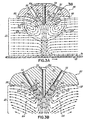
- the air deflecting member 116a positioned upstream of the nosepiece 82 has an outer surface 122, such as a radiused or otherwise curved surface, that is configured to deflect the entrained air 20 moving toward the die tip 10, due to aspiration caused by the high velocity air jets 114 and to air movement caused by the moving substrate 18, in a direction away from the air discharge outlets 110 and the wall 84 of the nosepiece 82 as shown in Figs. 3A and 3B .
- the air deflecting member 116a positioned upstream of the nosepiece 82 is further configured to deflect the entrained air 20 moving toward the die tip 10 at least partially toward the substrate 18, and to create a vortex, indicated diagrammatically as numeral 124 in Figs. 3A and 3B , that provides a positive air flow in a direction away from the air discharge outlets 110.
- the air deflecting member 116b positioned downstream of the nosepiece 82 also has an outer surface 122, such as a radiused or otherwise curved surface, that is configured to deflect the entrained air 20 moving toward the die tip 10, due to aspiration caused by the high velocity air jets 114, in a direction away from the air discharge outlets 110 and the wall 86 of the nosepiece 82.
- the air deflecting member 116b is further configured to deflect the entrained air 20 at least partially toward the substrate 18, and to create a vortex 124 that provides a positive air flow in a direction away from the air discharge outlets 110.
- a curved outer surface 122 is shown on air deflecting members 116a, 116b, it is contemplated that other surface configurations or shapes, including one or more non-curved surfaces, are possible as well that will function to divert the flow of turbulent entrained air 20 away from the air discharge outlets 110 and refocus the entrained air 20 into an accurate, open-channel flow in accordance with the principles of the present invention as shown in Fig. 3A .
- the uniformity of the process air, high velocity air and entrained air combined is increased, since the entrained air combines with the high velocity air at a point further away from the air discharge outlets 110 than would otherwise occur, as shown in Fig.
- This combination of the high velocity air and entrained air reduces the effect of the moving entrained air on the high velocity air, and reduces the amount of dust or other particles built up at the die tip 10.
- the air deflecting members 116a, 116b improve efficiency and focus of the pattern of the filaments 14 applied to the moving substrate 18.
- Each air deflecting member 116a, 116b has an inner wall 126 ( Figs. 3A and 3B ) that is generally parallel with the converging walls 84 and 86 of the nosepiece 82 to shield the air discharge outlets 110 from the entrained air 20.
- the air deflecting members 116a, 116b may be integral with the base member 80 or separately attached to extend outwardly from the lowermost surface 118 of the base member 80. While a pair of air deflecting members 116a, 116b is shown, it is contemplated that only one air deflecting member 116a may be provided upstream of the nosepiece 82 to contact and deflect the entrained air 20 moving toward the die tip 10 as described in detail above.
- the elongated slots 108 formed on the opposite sides of the nosepiece 82 serve two important functions. First, the slots 108 intersect the air flow passages 92 in a manner that forms circular-shaped air discharge outlets 110 at terminating ends of the air flow passages 92. The circular-shaped air discharge outlets 110 improve the behavior of the high velocity air jets 114 and also increase air efficiency over elliptical air discharge outlets of the past. Secondly, the elongated slots 108, in combination with the air deflecting members 116a, 116b, shield the air discharge outlets 110 from the entrained air 20 moving toward the die tip 10.
- the air deflecting members 116a, 116b serve to deflect the entrained air 20 in a direction away from the air discharge outlets 110 and the walls 84, 86 of the nosepiece 82. This protects the air discharge outlets 110 from the buildup of dust and other debris in the vicinity of the nosepiece 82 that would otherwise lead to partial or complete blockage of one or more of the air discharge outlets 110.
- the air deflecting members 116a, 116b thereby extend the life cycle of the die tips 10 and improve both spray efficiency and reliability. Further, the Aself-cleaning@ capability of die tip 10 reduces the need for expensive dust removal systems in the vicinity of the meltblowing dispensing system.
Claims (14)
- Embout de filière (10) destiné à être utilisé pour la distribution d'un matériau liquide sur un substrat mobile (18) comportant une couche d'air entraîné se déplaçant dans une direction commune, comprenant:un élément de base (80);au moins un passage d'écoulement du liquide (94) formé dans ledit élément de base (80), se terminant dans une sortie de distribution du liquide (104), capable de distribuer le matériau liquide vers le substrat (18); au moins un passage d'écoulement d'air (92) formé dans ledit élément de base (80), se terminant dans une sortie de décharge d'air (110), capable de décharger l'air vers le liquide distribué à partir de ladite sortie de distribution du liquide (104) et caractérisé parun déflecteur d'air (115) s'étendant vers l'extérieur dudit élément de base (80) et adapté pour s'étendre vers le substrat (18), ledit déflecteur d'air (115) étant capable de dévier l'air entraîné en écoulement dans une direction allant à l'écart de ladite sortie de décharge d'air (110).
- Embout de filière selon la revendication 1, caractérisé en outre en ce que ledit déflecteur d'air (115) comprend une paire d'éléments de déviation de l'air (116a, 116b) agencée dans une relation espacée à l'extérieur de ladite sortie de distribution du liquide (104).
- Embout de filière selon la revendication 1, comprenant en outre:un bec (82), s'étendant vers l'extérieur dudit élément de base (80) et adapté pour s'étendre vers le substrat (18), ledit bec (82) se terminant dans un sommet (88) s'étendant sur pratiquement l'ensemble de la largeur dudit élément de base (80);plusieurs passages d'écoulement du liquide (94) formés dans ledit élément de base (80), se terminant dans plusieurs sorties de distribution du liquide (104) formées dans une relation espacée le long dudit sommet (88);plusieurs passages d'écoulement d'air (92) formés dans ledit élément de base (80), se terminant dans plusieurs sorties de décharge d'air (110) formées dans une relation espacée dans une paire de rangées parallèles agencées le long des côtés opposés dudit bec (82); et caractérisé en ce que ledit déflecteur d'air (115) comprend:au moins un élément de déviation de l'air agencé à l'extérieur de l'une desdites rangées parallèles (98, 100) des sorties de décharge d'air (110).
- Embout de filière selon la revendication 3, caractérisé en outre en ce que ledit au moins un élément déflecteur de l'air (116a, 116b) s'étend sur pratiquement l'ensemble de la largeur dudit élément de base (80) et de manière pratiquement parallèle audit bec (82).
- Embout de filière selon la revendication 4, dans lequel ledit bec (82) comprend une paire de parois convergentes (84, 86) se rencontrant au niveau dudit sommet (88), et caractérisé en outre en ce que ledit au moins un élément de déviation de l'air comporte une paroi interne (126) espacée de l'une desdites parois convergentes (84, 86) et s'étendant en général de manière parallèle à celle-ci.
- Embout de filière selon la revendication 5, caractérisé en outre en ce que ledit au moins un élément de déviation de l'air (116a, 116b) comporte une paroi externe courbée, adaptée pour contacter et dévier l'air entraîné en écoulement dans une direction allant à l'écart de l'une desdites rangées parallèles des sorties de décharge d'air (110).
- Procédé de distribution d'un matériau liquide à partir d'un embout de filière (10), comportant plusieurs sorties de distribution du liquide (104) et plusieurs sorties de décharge d'air (110) qui y sont formées, vers un substrat mobile (18) comportant une couche d'air entraîné s'écoulant dans une direction commune, comprenant les étapes ci-dessous:distribution du matériau liquide à partir des plusieurs sorties de distribution du liquide (104) vers le substrat (18);décharge de l'air à partir des plusieurs sorties de décharge d'air (110) vers le matériau liquide distribué à partir des plusieurs sorties de distribution du liquide (104); et caractérisé par l'étape ci-dessous:déviation de l'air entraîné en écoulement dans une direction allant à l'écart des plusieurs sorties de décharge d'air (110).
- Procédé selon la revendication 7, caractérisé en outre en ce que l'air entraîné en écoulement est dévié au moins en partie vers le substrat (18).
- Procédé selon la revendication 7, caractérisé en outre par l'étape de formation d'un tourbillon dans l'air entraîné en écoulement pour établir un écoulement d'air positif dans une direction allant à l'écart des plusieurs sorties de décharge d'air (110).
- Embout de filière selon la revendication 1, comprenant en outre:un bec (82), s'étendant vers l'extérieur dudit élément de base (80) et adapté pour s'étendre vers le substrat, ledit bec se terminant dans un sommet (88) s'étendant sur pratiquement l'ensemble de la largeur dudit élément de base (80).plusieurs passages d'écoulement du liquide (94) formés dans ledit élément de base (80), se terminant dans plusieurs sorties de distribution du liquide (104) formées dans une relation espacée le long dudit sommet (88), chacun étant capable de distribuer le matériau liquide vers le substrat (18);plusieurs passages d'écoulement d'air (92) formés dans ledit élément de base (80), se terminant dans plusieurs sorties de décharge d'air (110) formées dans une relation espacée dans une paire de rangées parallèles agencées le long des côtés opposés dudit bec (82);et caractérisé en ce que ledit déflecteur d'air (115) comprend une paire d'éléments de déviation de l'air (116a, 116b), chacun étant agencé dans une relation espacée à l'extérieur de l'une desdites rangées parallèles des sorties de décharge d'air (110).
- Embout de filière selon la revendication 10, caractérisé en outre en ce que ladite paire d'éléments de déviation de l'air (116a, 116b) s'étend sur pratiquement l'ensemble de la largeur dudit élément de base et de manière pratiquement parallèle audit bec (82).
- Embout de filière selon la revendication 11, dans lequel ledit bec (82) comprend une paire de parois convergentes (84, 86) se rencontrant au niveau dudit sommet (88), et caractérisé en outre en ce que chacune de ladite paire d'éléments de déviation d'air (116a, 116b) comporte une paroi interne (126) espacée de l'une desdites parois convergentes (84, 86) et s'étendant en général de manière parallèle à celle-ci.
- Embout de filière selon la revendication 11, caractérisé en outre en ce que chacun desdits éléments de déviation de l'air (116a, 116b) comporte une paroi externe courbée adaptée pour contacter et dévier l'air entraîné en écoulement dans une direction allant à l'écart de l'une desdites rangées parallèles des sorties de décharge d'air (110).
- Embout de filière selon la revendication 1, caractérisé en outre en ce que ledit déflecteur (115) comprend au moins un élément de déviation de l'air (116a, 116b) agencé à l'extérieur de ladite sortie de distribution du liquide (104).
Applications Claiming Priority (2)
| Application Number | Priority Date | Filing Date | Title |
|---|---|---|---|
| US09/697,397 US6378784B1 (en) | 2000-10-27 | 2000-10-27 | Dispensing system using a die tip having an air foil |
| US697397 | 2000-10-27 |
Publications (3)
| Publication Number | Publication Date |
|---|---|
| EP1201320A2 EP1201320A2 (fr) | 2002-05-02 |
| EP1201320A3 EP1201320A3 (fr) | 2005-06-01 |
| EP1201320B1 true EP1201320B1 (fr) | 2008-02-20 |
Family
ID=24800986
Family Applications (1)
| Application Number | Title | Priority Date | Filing Date |
|---|---|---|---|
| EP01125205A Expired - Lifetime EP1201320B1 (fr) | 2000-10-27 | 2001-10-24 | Buse d'extrusion avec profil aérodynamique |
Country Status (3)
| Country | Link |
|---|---|
| US (1) | US6378784B1 (fr) |
| EP (1) | EP1201320B1 (fr) |
| DE (1) | DE60132870T2 (fr) |
Families Citing this family (23)
| Publication number | Priority date | Publication date | Assignee | Title |
|---|---|---|---|---|
| US6520426B2 (en) * | 2000-01-26 | 2003-02-18 | Spraying Systems Co. | Sanitary spray nozzle for spray guns |
| EP1243342B9 (fr) | 2001-03-22 | 2010-02-17 | Nordson Corporation | Système de distribution universel pour extrusion assistée par air de filaments liquides |
| US6619566B2 (en) | 2001-03-22 | 2003-09-16 | Nordson Corporation | Universal dispensing system for air assisted extrusion of liquid filaments |
| US6669057B2 (en) * | 2001-10-31 | 2003-12-30 | Nordson Corporation | High-speed liquid dispensing modules |
| US6972104B2 (en) * | 2003-12-23 | 2005-12-06 | Kimberly-Clark Worldwide, Inc. | Meltblown die having a reduced size |
| CN1681033A (zh) * | 2004-04-06 | 2005-10-12 | 皇家飞利浦电子股份有限公司 | 光盘播放系统的纠错机制 |
| US20050271806A1 (en) * | 2004-06-03 | 2005-12-08 | Nordson Corporation | Dispenser and method for non-contact dispensing of adhesive |
| US20050268845A1 (en) * | 2004-06-03 | 2005-12-08 | Nordson Corporation | Apparatus and nozzle plate for dispensing liquid material |
| US7316552B2 (en) * | 2004-12-23 | 2008-01-08 | Kimberly-Clark Worldwide, Inc. | Low turbulence die assembly for meltblowing apparatus |
| US8061564B2 (en) * | 2006-11-15 | 2011-11-22 | Nordson Corporation | Liquid dispensing apparatus including an attachment member |
| US9168554B2 (en) | 2011-04-11 | 2015-10-27 | Nordson Corporation | System, nozzle, and method for coating elastic strands |
| US9156053B2 (en) | 2011-10-27 | 2015-10-13 | Graco Minnesota Inc. | Melter |
| IN2014DN03195A (fr) | 2011-10-27 | 2015-05-22 | Graco Minnesota Inc | |
| US9682392B2 (en) | 2012-04-11 | 2017-06-20 | Nordson Corporation | Method for applying varying amounts or types of adhesive on an elastic strand |
| US9034425B2 (en) | 2012-04-11 | 2015-05-19 | Nordson Corporation | Method and apparatus for applying adhesive on an elastic strand in a personal disposable hygiene product |
| US8939330B2 (en) | 2013-03-13 | 2015-01-27 | Graco Minnesota Inc. | Removable module service seat |
| US11338311B2 (en) * | 2014-04-01 | 2022-05-24 | Illinois Tool Works Inc. | Fluid application device having a nozzle with individually metered orifice or orifices |
| CN104399645A (zh) * | 2014-11-18 | 2015-03-11 | 泉州新日成热熔胶设备有限公司 | 一种高精度热熔胶喷嘴及热熔胶枪 |
| US9796492B2 (en) | 2015-03-12 | 2017-10-24 | Graco Minnesota Inc. | Manual check valve for priming a collapsible fluid liner for a sprayer |
| US10304705B2 (en) * | 2015-12-10 | 2019-05-28 | Beijing Naura Microelectronics Equipment Co., Ltd. | Cleaning device for atomizing and spraying liquid in two-phase flow |
| CN111556909B (zh) | 2017-11-22 | 2024-04-09 | 挤压集团公司 | 熔喷模头尖端组件和方法 |
| CN115739435A (zh) | 2019-05-31 | 2023-03-07 | 固瑞克明尼苏达有限公司 | 手持式流体喷雾器 |
| US11809186B2 (en) * | 2020-02-19 | 2023-11-07 | Danny Muallem | Robotic biocide dispenser and cleaner |
Family Cites Families (11)
| Publication number | Priority date | Publication date | Assignee | Title |
|---|---|---|---|---|
| US3773263A (en) * | 1972-01-14 | 1973-11-20 | S K M Stains | Paint spray-gun head |
| US4687137A (en) | 1986-03-20 | 1987-08-18 | Nordson Corporation | Continuous/intermittent adhesive dispensing apparatus |
| US4891249A (en) | 1987-05-26 | 1990-01-02 | Acumeter Laboratories, Inc. | Method of and apparatus for somewhat-to-highly viscous fluid spraying for fiber or filament generation, controlled droplet generation, and combinations of fiber and droplet generation, intermittent and continuous, and for air-controlling spray deposition |
| US4983109A (en) | 1988-01-14 | 1991-01-08 | Nordson Corporation | Spray head attachment for metering gear head |
| US4949668A (en) | 1988-06-16 | 1990-08-21 | Kimberly-Clark Corporation | Apparatus for sprayed adhesive diaper construction |
| US4957783A (en) * | 1988-10-05 | 1990-09-18 | Nordson Corporation | Method and apparatus for dispensing droplets of molten thermoplastic adhesive |
| US5145689A (en) | 1990-10-17 | 1992-09-08 | Exxon Chemical Patents Inc. | Meltblowing die |
| US5196207A (en) * | 1992-01-27 | 1993-03-23 | Kimberly-Clark Corporation | Meltblown die head |
| US5618566A (en) | 1995-04-26 | 1997-04-08 | Exxon Chemical Patents, Inc. | Modular meltblowing die |
| US5728219A (en) | 1995-09-22 | 1998-03-17 | J&M Laboratories, Inc. | Modular die for applying adhesives |
| EP0987352A3 (fr) * | 1998-09-16 | 2000-05-03 | Nordson Corporation | Matrice modulaire de soufflage à chaud |
-
2000
- 2000-10-27 US US09/697,397 patent/US6378784B1/en not_active Expired - Fee Related
-
2001
- 2001-10-24 DE DE60132870T patent/DE60132870T2/de not_active Expired - Fee Related
- 2001-10-24 EP EP01125205A patent/EP1201320B1/fr not_active Expired - Lifetime
Also Published As
| Publication number | Publication date |
|---|---|
| DE60132870T2 (de) | 2009-02-19 |
| US6378784B1 (en) | 2002-04-30 |
| EP1201320A2 (fr) | 2002-05-02 |
| EP1201320A3 (fr) | 2005-06-01 |
| DE60132870D1 (de) | 2008-04-03 |
Similar Documents
| Publication | Publication Date | Title |
|---|---|---|
| EP1201320B1 (fr) | Buse d'extrusion avec profil aérodynamique | |
| US6540831B1 (en) | Method and apparatus for applying a controlled pattern of fibrous material to a moving substrate | |
| EP1932598B1 (fr) | Buse multi-plaque et procédé pour la distribution d'un motif aléatoire de filaments adhésifs | |
| US7950346B2 (en) | Module, nozzle and method for dispensing controlled patterns of liquid material | |
| US6719846B2 (en) | Device and method for applying adhesive filaments to materials such as strands or flat substrates | |
| JP2554731B2 (ja) | 計量歯車ヘッド用のスプレヘッド付属具及びホットメルト接着剤を塗布する方法 | |
| JP5502361B2 (ja) | ランダムパターンで接着剤フィラメントを吐出するノズルおよび方法 | |
| US7255292B2 (en) | Module and nozzle for dispensing controlled patterns of liquid material | |
| JP2002505951A (ja) | ホットメルト接着剤または他のポリマー溶融物を塗布するためのセグメントダイ | |
| US6863225B2 (en) | Device and method for applying adhesive to materials such as strands | |
| JP4638674B2 (ja) | ノズル、及び液体材料を吐出する方法 | |
| US7462240B2 (en) | Module, nozzle and method for dispensing controlled patterns of liquid material | |
| US7175108B2 (en) | Applicator and nozzle for dispensing controlled patterns of liquid material | |
| EP1407830A2 (fr) | Buse segmentée d'application d'adhésifs thermofusibles ou d'autres polymères fondus |
Legal Events
| Date | Code | Title | Description |
|---|---|---|---|
| PUAI | Public reference made under article 153(3) epc to a published international application that has entered the european phase |
Free format text: ORIGINAL CODE: 0009012 |
|
| AK | Designated contracting states |
Kind code of ref document: A2 Designated state(s): AT BE CH CY DE DK ES FI FR GB GR IE IT LI LU MC NL PT SE TR |
|
| AX | Request for extension of the european patent |
Free format text: AL;LT;LV;MK;RO;SI |
|
| PUAL | Search report despatched |
Free format text: ORIGINAL CODE: 0009013 |
|
| AK | Designated contracting states |
Kind code of ref document: A3 Designated state(s): AT BE CH CY DE DK ES FI FR GB GR IE IT LI LU MC NL PT SE TR |
|
| AX | Request for extension of the european patent |
Extension state: AL LT LV MK RO SI |
|
| 17P | Request for examination filed |
Effective date: 20051201 |
|
| AKX | Designation fees paid |
Designated state(s): DE IT |
|
| GRAP | Despatch of communication of intention to grant a patent |
Free format text: ORIGINAL CODE: EPIDOSNIGR1 |
|
| GRAS | Grant fee paid |
Free format text: ORIGINAL CODE: EPIDOSNIGR3 |
|
| GRAA | (expected) grant |
Free format text: ORIGINAL CODE: 0009210 |
|
| AK | Designated contracting states |
Kind code of ref document: B1 Designated state(s): DE IT |
|
| REF | Corresponds to: |
Ref document number: 60132870 Country of ref document: DE Date of ref document: 20080403 Kind code of ref document: P |
|
| PLBE | No opposition filed within time limit |
Free format text: ORIGINAL CODE: 0009261 |
|
| STAA | Information on the status of an ep patent application or granted ep patent |
Free format text: STATUS: NO OPPOSITION FILED WITHIN TIME LIMIT |
|
| 26N | No opposition filed |
Effective date: 20081121 |
|
| PGFP | Annual fee paid to national office [announced via postgrant information from national office to epo] |
Ref country code: DE Payment date: 20081022 Year of fee payment: 8 |
|
| PGFP | Annual fee paid to national office [announced via postgrant information from national office to epo] |
Ref country code: IT Payment date: 20081024 Year of fee payment: 8 |
|
| PG25 | Lapsed in a contracting state [announced via postgrant information from national office to epo] |
Ref country code: DE Free format text: LAPSE BECAUSE OF NON-PAYMENT OF DUE FEES Effective date: 20100501 |
|
| PG25 | Lapsed in a contracting state [announced via postgrant information from national office to epo] |
Ref country code: IT Free format text: LAPSE BECAUSE OF NON-PAYMENT OF DUE FEES Effective date: 20091024 |