EP1200873B1 - Image display apparatus - Google Patents
Image display apparatus Download PDFInfo
- Publication number
- EP1200873B1 EP1200873B1 EP00946111A EP00946111A EP1200873B1 EP 1200873 B1 EP1200873 B1 EP 1200873B1 EP 00946111 A EP00946111 A EP 00946111A EP 00946111 A EP00946111 A EP 00946111A EP 1200873 B1 EP1200873 B1 EP 1200873B1
- Authority
- EP
- European Patent Office
- Prior art keywords
- shutter
- light
- display apparatus
- image display
- elements
- Prior art date
- Legal status (The legal status is an assumption and is not a legal conclusion. Google has not performed a legal analysis and makes no representation as to the accuracy of the status listed.)
- Expired - Lifetime
Links
- 230000003287 optical effect Effects 0.000 claims abstract description 3
- 239000011159 matrix material Substances 0.000 claims description 5
- 230000001419 dependent effect Effects 0.000 claims 1
- 210000004027 cell Anatomy 0.000 description 17
- 239000004973 liquid crystal related substance Substances 0.000 description 13
- 210000002858 crystal cell Anatomy 0.000 description 9
- 230000036755 cellular response Effects 0.000 description 7
- 230000005540 biological transmission Effects 0.000 description 5
- 238000013459 approach Methods 0.000 description 4
- 230000000694 effects Effects 0.000 description 4
- 230000003247 decreasing effect Effects 0.000 description 3
- 230000000593 degrading effect Effects 0.000 description 1
- 230000001934 delay Effects 0.000 description 1
- 230000003111 delayed effect Effects 0.000 description 1
- 230000002939 deleterious effect Effects 0.000 description 1
- 238000005286 illumination Methods 0.000 description 1
- 230000000977 initiatory effect Effects 0.000 description 1
- 238000000034 method Methods 0.000 description 1
- 238000012986 modification Methods 0.000 description 1
- 230000004048 modification Effects 0.000 description 1
- 230000003068 static effect Effects 0.000 description 1
Images


Classifications
-
- G—PHYSICS
- G02—OPTICS
- G02F—OPTICAL DEVICES OR ARRANGEMENTS FOR THE CONTROL OF LIGHT BY MODIFICATION OF THE OPTICAL PROPERTIES OF THE MEDIA OF THE ELEMENTS INVOLVED THEREIN; NON-LINEAR OPTICS; FREQUENCY-CHANGING OF LIGHT; OPTICAL LOGIC ELEMENTS; OPTICAL ANALOGUE/DIGITAL CONVERTERS
- G02F1/00—Devices or arrangements for the control of the intensity, colour, phase, polarisation or direction of light arriving from an independent light source, e.g. switching, gating or modulating; Non-linear optics
- G02F1/01—Devices or arrangements for the control of the intensity, colour, phase, polarisation or direction of light arriving from an independent light source, e.g. switching, gating or modulating; Non-linear optics for the control of the intensity, phase, polarisation or colour
- G02F1/13—Devices or arrangements for the control of the intensity, colour, phase, polarisation or direction of light arriving from an independent light source, e.g. switching, gating or modulating; Non-linear optics for the control of the intensity, phase, polarisation or colour based on liquid crystals, e.g. single liquid crystal display cells
- G02F1/133—Constructional arrangements; Operation of liquid crystal cells; Circuit arrangements
- G02F1/1333—Constructional arrangements; Manufacturing methods
- G02F1/1347—Arrangement of liquid crystal layers or cells in which the final condition of one light beam is achieved by the addition of the effects of two or more layers or cells
-
- H—ELECTRICITY
- H04—ELECTRIC COMMUNICATION TECHNIQUE
- H04N—PICTORIAL COMMUNICATION, e.g. TELEVISION
- H04N5/00—Details of television systems
- H04N5/74—Projection arrangements for image reproduction, e.g. using eidophor
- H04N5/7416—Projection arrangements for image reproduction, e.g. using eidophor involving the use of a spatial light modulator, e.g. a light valve, controlled by a video signal
- H04N5/7441—Projection arrangements for image reproduction, e.g. using eidophor involving the use of a spatial light modulator, e.g. a light valve, controlled by a video signal the modulator being an array of liquid crystal cells
- H04N2005/745—Control circuits therefor
Definitions
- the present invention relates to an image display apparatus comprising a light valve.
- a light valve is a device which has light transmission or reflection characteristics that can be made to vary with an applied electrical quantity.
- LCD liquid crystal display
- LCD panels are one example of a well known device used as a light valve in image display systems within a wide range of equipment. LCD panels are passive (do not generate light) and must be illuminated by an external light source. For instance, conventional LCD panels may either be back lit with a dedicated light source or may be reflective relying on ambient light for illumination. LCD panels have also been developed for use as light valves in image projection systems.
- a typical LCD panel comprises a matrix array of liquid crystal cells each of which constitutes a single pixel of the displayed image.
- the image displayed is determined by the state of each cell which is controlled by appropriate electrical drivers applied to individual columns and lines of cells in the matrix.
- video data is supplied to column drivers and each line of the panel (and thus the image) is updated in sequence by line drivers.
- the time duration required to update a single line is referred to as the line period and the time duration between successive updates of any given line is referred to as a frame period.
- the individual liquid crystal cell settings of each line remain fixed during a frame period so that each line acts as a light valve and the image displayed is flicker free.
- a well known problem affecting conventional LCDs is the "smearing" of images, or portions of an image, which move rapidly across the display.
- the most widely used form of liquid crystal cell is the twist nematic cell which has a typical response period which falls in the range of 10 to 40 milliseconds.
- video display screens conventionally operate at around 50Hz thus having a frame period of the order of 20 milliseconds. As the frame period approaches or exceeds the LCD cell response time, visible artefacts, such as loss of contrast of the leading edge and smear of the trailing edge of a moving image element, are introduced into the display with a resultant loss of dynamic resolution.
- One known method of combating this problem is to operate the LCD panel at an elevated temperature to reduce the viscosity of the liquid crystal and thereby reduce response time. An improvement of about 30% of the cell response time can be obtained in this way but care has to be taken to ensue temperatures do not exceed the liquid crystal stability limit above which the panel may cease to work.
- an image display apparatus comprising a light valve for controlling at least the intensity of light projected along an optical path from a light source through the light valve, the light valve defining a plurality of light transmitting elements, the elements being such that, at least the translucency of each element may be adjusted periodically such that the translucency of each element is substantially constant except during intervals within which the translucency is being adjusted, wherein a shutter is provided to obstruct the light path through at least one of the light transmitting elements during intervals within which the translucency of the element is being adjusted.
- the apparatus according to the present invention uses one or more shutters to decrease the effective display response time and hence improve the quality of display, enabling display of an image with moving high contrast elements without smear. Further details of the manner in which this is achieved, and further advantageous features of the invention, will be apparent from the following description.
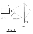
- the illustrated projection system is a back projection system comprising an LCD projector and lens system 1, a back projection screen 2, and a fast acting shutter 3 mounted in the image projection path between the projector 1 and screen 2.
- the projector 1 may be a conventional projector comprising a conventional LCD panel and lens system.
- a conventional LCD panel which may be incorporated in the projector 1 is schematically illustrated in Figure 2.
- the panel 4 comprises a rectangular matrix array of liquid crystal cells arranged in lines and columns (not illustrated).
- Video data is supplied to each cell by the application of a voltage to each respective column of cells by a column driver 5.
- line data is provided to each cell of successive lines of the matrix array by a line driver 6. Since the LCD panel and its operation may be entirely conventional further details of that operation not be given here.
- each line of liquid crystal cells is updated in sequence once every frame period, the time it takes to update each line being a line period.
- This image updating scheme is graphically illustrated in Figure 3 which shows how the frame period of each successive line in the display is offset from the previous line by one line period.
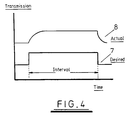
- FIG. 4 A typical transmission response of an individual LCD cell is illustrated in Figure 4.
- line 7 is the desired cell response over time illustrating that the cell is required to switch sharply from low to high transmission states (and vice versa) at the beginning and end of a time interval of one or more frame periods.
- the actual response of a typical cell to the control input corresponding to line 7 is illustrated by line 8. This shows that when the cell is set to transmit a high light level, the cell transmission initially increases with time and thus approaches the desired level asymptotically. Similarly, at the end of the time interval when the cell is "turned off", the cell transmission level does not drop instantly to zero but falls to zero asymptotically.
- These delays in the cell response produce visible artefacts in the pixel displayed by the cell, resulting in a "soft" leading edge and a "tail” at the trailing edge degrading the displayed picture and reducing the dynamic resolution compared with static resolution.
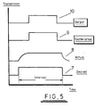
- line 10 illustrates the actual output of the cell, i.e. the projected pixel, as a result of the shutter operation. This shows how the asymptotic regions of the cell response are eliminated from the projected pixel and the response time is effectively decreased.
- the time period indicated as t1 is the shutter open period and the time period indicated as t2 is the shutter closed period, the combination t1 plus t2 being equal to the frame period.
- the time period indicated as d1 is the delay between initiation of the first line period and the opening of the shutter. It will be seen from Figure 6 that with the illustrated shutter timing scheme the LCD line numbers 3, 4 and 5 will be sharpened for dynamic images whereas lines 1, 2, 6, 7 and 8 will not. As mentioned above, the overall brightness of the displayed image will be reduced, the reduction in pixel brightness being tl/(tl + t2) for each pixel compared with the output that would be achieved without the shutter.
- Increasing t1 without changing the delay d1 will increase the brightness of the image but will mean that line 3 (at least) will not be sharpened. Conversely, reducing t1 will add other lines (firstly line 2 and then line 1, depending on the amount of reduction) to the sharpened image at the expense of further reducing the overall image brightness. Thus, it is possible to trade off the image brightness against the number of lines sharpened. Furthermore, by varying the delay d1 it is possible to adjust which group of lines will actually be sharpened. Non-sharpened lines are decreased in brightness but otherwise are not affected.
- FIG 7 is a schematic illustration of a shutter assembly comprising three horizontal shutter elements. If the shutter is mounted so that each element is horizontal and aligned with the display lines then each element of the shutter will affect only a limited number of lines.
- Figure 8 is an illustration of how a three element shutter such as that illustrated in Figure 7 could be used to sharpen all of the lines of an eight line display. In the illustrated arrangement the top element 11 of to the shutter affects lines 1 and 2, the middle 12 element affects lines 3, 4 and 5, and the bottom element 13 affects lines 6, 7, and 8. In each case the shutter open period (t1) is the same but the open period for successive horizontal shutter elements is delayed by a time corresponding to the frame period divided by the number of horizontal elements (i.e. three).
- FIG. 9 A practical arrangement of such a projector system is illustrated in Figure 9.
- an LCD projector 14 and associated relay lens 15 produce an intermediate image on a shutter 16 positioned in an intermediate image plane.
- a field lens 17 adjacent the image plane, and a projection lens 18 relay the image passing through the shutter onto a back projection screen 19.
- the structure of the shutter will be imposed on the projected image so that it is desirable to displace the shutter slightly from the image plane (as is normally done with the field lens for the same reason).
- the invention is not limited in application to any particular type of light valve or LCD panel, or any particular type of image display system.
- the display system need not be a back projection system or indeed a projection display system at all. Rather, the invention can be utilised in other display systems incorporating a light valve such as, for instance, a liquid crystal display.
Landscapes
- Physics & Mathematics (AREA)
- Nonlinear Science (AREA)
- Chemical & Material Sciences (AREA)
- Crystallography & Structural Chemistry (AREA)
- Multimedia (AREA)
- General Physics & Mathematics (AREA)
- Optics & Photonics (AREA)
- Engineering & Computer Science (AREA)
- Mathematical Physics (AREA)
- Signal Processing (AREA)
- Liquid Crystal (AREA)
- Liquid Crystal Display Device Control (AREA)
- Control Of Indicators Other Than Cathode Ray Tubes (AREA)
- Endoscopes (AREA)
- Controls And Circuits For Display Device (AREA)
- Magnetic Resonance Imaging Apparatus (AREA)
- Transforming Electric Information Into Light Information (AREA)
- Projection Apparatus (AREA)
- Measuring Pulse, Heart Rate, Blood Pressure Or Blood Flow (AREA)
Applications Claiming Priority (3)
| Application Number | Priority Date | Filing Date | Title |
|---|---|---|---|
| GBGB9917973.1A GB9917973D0 (en) | 1999-07-31 | 1999-07-31 | Image display apparatus |
| GB9917973 | 1999-07-31 | ||
| PCT/GB2000/002729 WO2001009676A1 (en) | 1999-07-31 | 2000-07-14 | Image display apparatus |
Publications (2)
| Publication Number | Publication Date |
|---|---|
| EP1200873A1 EP1200873A1 (en) | 2002-05-02 |
| EP1200873B1 true EP1200873B1 (en) | 2006-05-17 |
Family
ID=10858275
Family Applications (1)
| Application Number | Title | Priority Date | Filing Date |
|---|---|---|---|
| EP00946111A Expired - Lifetime EP1200873B1 (en) | 1999-07-31 | 2000-07-14 | Image display apparatus |
Country Status (10)
| Country | Link |
|---|---|
| US (1) | US6967641B1 (enExample) |
| EP (1) | EP1200873B1 (enExample) |
| JP (1) | JP2003506745A (enExample) |
| AT (1) | ATE326714T1 (enExample) |
| AU (1) | AU5999600A (enExample) |
| CA (1) | CA2380526C (enExample) |
| DE (1) | DE60028041D1 (enExample) |
| GB (1) | GB9917973D0 (enExample) |
| NO (1) | NO325896B1 (enExample) |
| WO (1) | WO2001009676A1 (enExample) |
Families Citing this family (10)
| Publication number | Priority date | Publication date | Assignee | Title |
|---|---|---|---|---|
| US6741323B2 (en) * | 2002-08-12 | 2004-05-25 | Digital Theater Systems, Inc. | Motion picture subtitle system and method |
| US7221759B2 (en) * | 2003-03-27 | 2007-05-22 | Eastman Kodak Company | Projector with enhanced security camcorder defeat |
| US7374290B2 (en) | 2003-06-13 | 2008-05-20 | Sony Corporation | Projection type display device |
| JP3843973B2 (ja) * | 2003-09-02 | 2006-11-08 | セイコーエプソン株式会社 | プロジェクタ |
| DE102004018344A1 (de) | 2004-04-15 | 2005-11-10 | Reinz-Dichtungs-Gmbh | Metallische Flachdichtung |
| JP2006098803A (ja) * | 2004-09-29 | 2006-04-13 | Toshiba Corp | 動画処理方法、動画処理装置および動画処理プログラム |
| US20070046594A1 (en) * | 2005-08-26 | 2007-03-01 | Pasch Nicholas F | Optical shutter for a display apparatus comprising an array of switches |
| JP2010175907A (ja) * | 2009-01-30 | 2010-08-12 | Victor Co Of Japan Ltd | 投射型表示装置及びその表示方法 |
| US20130147696A1 (en) * | 2011-12-12 | 2013-06-13 | Jani Edvin Penttilä | Display Moving Image Quality Improvement In 3D Barrier Type Display |
| WO2014041582A1 (ja) * | 2012-09-11 | 2014-03-20 | カラーリンク・ジャパン 株式会社 | 光学装置及びプロジェクション装置 |
Family Cites Families (9)
| Publication number | Priority date | Publication date | Assignee | Title |
|---|---|---|---|---|
| JPS57201295A (en) | 1981-06-04 | 1982-12-09 | Sony Corp | Two-dimensional address device |
| KR920007165B1 (ko) | 1989-01-31 | 1992-08-27 | 주식회사 금성사 | 비데오 프린터 겸용의 액정프로젝터 |
| JP2599309B2 (ja) * | 1989-11-22 | 1997-04-09 | パイオニア株式会社 | 液晶プロジェクタ |
| DE69224540T2 (de) | 1991-03-19 | 1998-06-25 | Hitachi Ltd | Verfahren zur Projektion eines durch Anwendung von Flüssigkristallanzeigen erhaltenen Bildes und Anzeigevorrichtung zur Durchführung des Verfahrens |
| KR960013313B1 (ko) | 1991-07-12 | 1996-10-02 | 가부시키가이샤 한도오따이 에네루기 겐큐쇼 | 전기광학 표시장치 |
| TW281734B (enExample) | 1993-06-20 | 1996-07-21 | Unic View Ltd | |
| US6243055B1 (en) * | 1994-10-25 | 2001-06-05 | James L. Fergason | Optical display system and method with optical shifting of pixel position including conversion of pixel layout to form delta to stripe pattern by time base multiplexing |
| US6204901B1 (en) | 1997-07-31 | 2001-03-20 | Duke University | Liquid crystal color shutters that include reflective polarizers that pass color components of light of a first polarization and that reflect a majority of color components of light of a second polarization |
| WO1999008257A1 (en) | 1997-08-05 | 1999-02-18 | Allan John Davie | Liquid crystal controlled display apparatus |
-
1999
- 1999-07-31 GB GBGB9917973.1A patent/GB9917973D0/en not_active Ceased
-
2000
- 2000-07-14 AU AU59996/00A patent/AU5999600A/en not_active Abandoned
- 2000-07-14 DE DE60028041T patent/DE60028041D1/de not_active Expired - Lifetime
- 2000-07-14 US US10/048,530 patent/US6967641B1/en not_active Expired - Fee Related
- 2000-07-14 JP JP2001514627A patent/JP2003506745A/ja active Pending
- 2000-07-14 WO PCT/GB2000/002729 patent/WO2001009676A1/en not_active Ceased
- 2000-07-14 AT AT00946111T patent/ATE326714T1/de not_active IP Right Cessation
- 2000-07-14 EP EP00946111A patent/EP1200873B1/en not_active Expired - Lifetime
- 2000-07-14 CA CA002380526A patent/CA2380526C/en not_active Expired - Fee Related
-
2002
- 2002-01-28 NO NO20020437A patent/NO325896B1/no not_active IP Right Cessation
Also Published As
| Publication number | Publication date |
|---|---|
| AU5999600A (en) | 2001-02-19 |
| US6967641B1 (en) | 2005-11-22 |
| NO20020437D0 (no) | 2002-01-28 |
| NO20020437L (no) | 2002-01-28 |
| EP1200873A1 (en) | 2002-05-02 |
| CA2380526A1 (en) | 2001-02-08 |
| ATE326714T1 (de) | 2006-06-15 |
| WO2001009676A1 (en) | 2001-02-08 |
| DE60028041D1 (de) | 2006-06-22 |
| JP2003506745A (ja) | 2003-02-18 |
| CA2380526C (en) | 2009-04-21 |
| NO325896B1 (no) | 2008-08-11 |
| GB9917973D0 (en) | 1999-09-29 |
Similar Documents
| Publication | Publication Date | Title |
|---|---|---|
| EP0478186B1 (en) | Display device | |
| JP4149699B2 (ja) | 時分割方式液晶表示装置及びそのカラー映像表示方法 | |
| KR100223724B1 (ko) | 칼라 표시 장치 및 그 어드레싱 회로 | |
| US7233304B1 (en) | Liquid crystal display apparatus | |
| KR100712471B1 (ko) | 시분할 방식 액정표시장치 및 그의 컬러영상표시방법 | |
| KR100346878B1 (ko) | 블럭리셋및보조메모리로다중화된메모리타이밍 | |
| JP4655341B2 (ja) | 表示装置 | |
| KR100241839B1 (ko) | 액정 디스플레이의 중간 표시 구동 방식 | |
| US7973781B2 (en) | Image display device and projector | |
| US8366275B2 (en) | Image display apparatus having at least two modulators for modulating light | |
| US20030132901A1 (en) | Field sequential color display device | |
| JP2982722B2 (ja) | 映像表示装置 | |
| US9406269B2 (en) | System and method for pulse width modulating a scrolling color display | |
| EP1200873B1 (en) | Image display apparatus | |
| US7012598B2 (en) | Liquid crystal display device and method for operating the same | |
| JP2000347323A (ja) | 画像表示装置 | |
| MXPA02004696A (es) | Reduccion de oscilacion mediante interpolacion de imagen. | |
| EP1100259B1 (en) | False contour correction apparatus and method in an image display system | |
| CN101013254A (zh) | 调制用于显示的图像 | |
| KR20010072321A (ko) | 컬러-순차적 액정 디스플레이에서 컬러 순도 증가시키는방법 및 장치 | |
| US6313820B1 (en) | Method of operating a ferroelectric liquid crystal spatial light modulator in non-DC balanced mode with decreased pixel sticking | |
| KR100724748B1 (ko) | 백라이트 유니트와 이를 이용한 액정표시장치 | |
| JP3503303B2 (ja) | 表示装置 | |
| KR0145632B1 (ko) | 계조가변형 투과필터를 갖춘 화상표시장치 | |
| JP2005521912A (ja) | 可変レートの行アドレッシング方法 |
Legal Events
| Date | Code | Title | Description |
|---|---|---|---|
| PUAI | Public reference made under article 153(3) epc to a published international application that has entered the european phase |
Free format text: ORIGINAL CODE: 0009012 |
|
| 17P | Request for examination filed |
Effective date: 20020211 |
|
| AK | Designated contracting states |
Kind code of ref document: A1 Designated state(s): AT BE CH CY DE DK ES FI FR GB GR IE IT LI LU MC NL PT SE |
|
| AX | Request for extension of the european patent |
Free format text: AL;LT;LV;MK;RO;SI |
|
| RAP1 | Party data changed (applicant data changed or rights of an application transferred) |
Owner name: THALES TRAINING AND SIMULATION LIMITED |
|
| 17Q | First examination report despatched |
Effective date: 20040720 |
|
| GRAP | Despatch of communication of intention to grant a patent |
Free format text: ORIGINAL CODE: EPIDOSNIGR1 |
|
| GRAS | Grant fee paid |
Free format text: ORIGINAL CODE: EPIDOSNIGR3 |
|
| GRAA | (expected) grant |
Free format text: ORIGINAL CODE: 0009210 |
|
| AK | Designated contracting states |
Kind code of ref document: B1 Designated state(s): AT BE CH CY DE DK ES FI FR GB GR IE IT LI LU MC NL PT SE |
|
| PG25 | Lapsed in a contracting state [announced via postgrant information from national office to epo] |
Ref country code: IT Free format text: LAPSE BECAUSE OF FAILURE TO SUBMIT A TRANSLATION OF THE DESCRIPTION OR TO PAY THE FEE WITHIN THE PRESCRIBED TIME-LIMIT;WARNING: LAPSES OF ITALIAN PATENTS WITH EFFECTIVE DATE BEFORE 2007 MAY HAVE OCCURRED AT ANY TIME BEFORE 2007. THE CORRECT EFFECTIVE DATE MAY BE DIFFERENT FROM THE ONE RECORDED. Effective date: 20060517 Ref country code: NL Free format text: LAPSE BECAUSE OF FAILURE TO SUBMIT A TRANSLATION OF THE DESCRIPTION OR TO PAY THE FEE WITHIN THE PRESCRIBED TIME-LIMIT Effective date: 20060517 Ref country code: FI Free format text: LAPSE BECAUSE OF FAILURE TO SUBMIT A TRANSLATION OF THE DESCRIPTION OR TO PAY THE FEE WITHIN THE PRESCRIBED TIME-LIMIT Effective date: 20060517 Ref country code: LI Free format text: LAPSE BECAUSE OF FAILURE TO SUBMIT A TRANSLATION OF THE DESCRIPTION OR TO PAY THE FEE WITHIN THE PRESCRIBED TIME-LIMIT Effective date: 20060517 Ref country code: CH Free format text: LAPSE BECAUSE OF FAILURE TO SUBMIT A TRANSLATION OF THE DESCRIPTION OR TO PAY THE FEE WITHIN THE PRESCRIBED TIME-LIMIT Effective date: 20060517 Ref country code: AT Free format text: LAPSE BECAUSE OF FAILURE TO SUBMIT A TRANSLATION OF THE DESCRIPTION OR TO PAY THE FEE WITHIN THE PRESCRIBED TIME-LIMIT Effective date: 20060517 |
|
| REG | Reference to a national code |
Ref country code: GB Ref legal event code: FG4D |
|
| REG | Reference to a national code |
Ref country code: CH Ref legal event code: EP |
|
| REG | Reference to a national code |
Ref country code: IE Ref legal event code: FG4D |
|
| REF | Corresponds to: |
Ref document number: 60028041 Country of ref document: DE Date of ref document: 20060622 Kind code of ref document: P |
|
| PG25 | Lapsed in a contracting state [announced via postgrant information from national office to epo] |
Ref country code: IE Free format text: LAPSE BECAUSE OF NON-PAYMENT OF DUE FEES Effective date: 20060714 |
|
| PG25 | Lapsed in a contracting state [announced via postgrant information from national office to epo] |
Ref country code: MC Free format text: LAPSE BECAUSE OF NON-PAYMENT OF DUE FEES Effective date: 20060731 |
|
| PG25 | Lapsed in a contracting state [announced via postgrant information from national office to epo] |
Ref country code: DK Free format text: LAPSE BECAUSE OF FAILURE TO SUBMIT A TRANSLATION OF THE DESCRIPTION OR TO PAY THE FEE WITHIN THE PRESCRIBED TIME-LIMIT Effective date: 20060817 Ref country code: SE Free format text: LAPSE BECAUSE OF FAILURE TO SUBMIT A TRANSLATION OF THE DESCRIPTION OR TO PAY THE FEE WITHIN THE PRESCRIBED TIME-LIMIT Effective date: 20060817 |
|
| PG25 | Lapsed in a contracting state [announced via postgrant information from national office to epo] |
Ref country code: DE Free format text: LAPSE BECAUSE OF FAILURE TO SUBMIT A TRANSLATION OF THE DESCRIPTION OR TO PAY THE FEE WITHIN THE PRESCRIBED TIME-LIMIT Effective date: 20060818 |
|
| PG25 | Lapsed in a contracting state [announced via postgrant information from national office to epo] |
Ref country code: ES Free format text: LAPSE BECAUSE OF FAILURE TO SUBMIT A TRANSLATION OF THE DESCRIPTION OR TO PAY THE FEE WITHIN THE PRESCRIBED TIME-LIMIT Effective date: 20060828 |
|
| PG25 | Lapsed in a contracting state [announced via postgrant information from national office to epo] |
Ref country code: PT Free format text: LAPSE BECAUSE OF FAILURE TO SUBMIT A TRANSLATION OF THE DESCRIPTION OR TO PAY THE FEE WITHIN THE PRESCRIBED TIME-LIMIT Effective date: 20061017 |
|
| NLV1 | Nl: lapsed or annulled due to failure to fulfill the requirements of art. 29p and 29m of the patents act | ||
| REG | Reference to a national code |
Ref country code: CH Ref legal event code: PL |
|
| ET | Fr: translation filed | ||
| PLBI | Opposition filed |
Free format text: ORIGINAL CODE: 0009260 |
|
| 26 | Opposition filed |
Opponent name: BARCO NV Effective date: 20070219 |
|
| PLAX | Notice of opposition and request to file observation + time limit sent |
Free format text: ORIGINAL CODE: EPIDOSNOBS2 |
|
| PLBB | Reply of patent proprietor to notice(s) of opposition received |
Free format text: ORIGINAL CODE: EPIDOSNOBS3 |
|
| PG25 | Lapsed in a contracting state [announced via postgrant information from national office to epo] |
Ref country code: GR Free format text: LAPSE BECAUSE OF FAILURE TO SUBMIT A TRANSLATION OF THE DESCRIPTION OR TO PAY THE FEE WITHIN THE PRESCRIBED TIME-LIMIT Effective date: 20060818 |
|
| PG25 | Lapsed in a contracting state [announced via postgrant information from national office to epo] |
Ref country code: LU Free format text: LAPSE BECAUSE OF NON-PAYMENT OF DUE FEES Effective date: 20060714 |
|
| PG25 | Lapsed in a contracting state [announced via postgrant information from national office to epo] |
Ref country code: CY Free format text: LAPSE BECAUSE OF FAILURE TO SUBMIT A TRANSLATION OF THE DESCRIPTION OR TO PAY THE FEE WITHIN THE PRESCRIBED TIME-LIMIT Effective date: 20060517 |
|
| PGFP | Annual fee paid to national office [announced via postgrant information from national office to epo] |
Ref country code: FR Payment date: 20100805 Year of fee payment: 11 |
|
| PGFP | Annual fee paid to national office [announced via postgrant information from national office to epo] |
Ref country code: GB Payment date: 20100714 Year of fee payment: 11 |
|
| PGFP | Annual fee paid to national office [announced via postgrant information from national office to epo] |
Ref country code: BE Payment date: 20100714 Year of fee payment: 11 |
|
| BERE | Be: lapsed |
Owner name: *THALES TRAINING AND SIMULATION LTD Effective date: 20110731 |
|
| GBPC | Gb: european patent ceased through non-payment of renewal fee |
Effective date: 20110714 |
|
| REG | Reference to a national code |
Ref country code: FR Ref legal event code: ST Effective date: 20120330 |
|
| PG25 | Lapsed in a contracting state [announced via postgrant information from national office to epo] |
Ref country code: FR Free format text: LAPSE BECAUSE OF NON-PAYMENT OF DUE FEES Effective date: 20110801 Ref country code: BE Free format text: LAPSE BECAUSE OF NON-PAYMENT OF DUE FEES Effective date: 20110731 |
|
| PG25 | Lapsed in a contracting state [announced via postgrant information from national office to epo] |
Ref country code: GB Free format text: LAPSE BECAUSE OF NON-PAYMENT OF DUE FEES Effective date: 20110714 |
|
| PLBD | Termination of opposition procedure: decision despatched |
Free format text: ORIGINAL CODE: EPIDOSNOPC1 |
|
| PLBM | Termination of opposition procedure: date of legal effect published |
Free format text: ORIGINAL CODE: 0009276 |
|
| STAA | Information on the status of an ep patent application or granted ep patent |
Free format text: STATUS: OPPOSITION PROCEDURE CLOSED |
|
| 27C | Opposition proceedings terminated |
Effective date: 20121115 |