EP1200208B1 - Machine for treating objects - Google Patents
Machine for treating objects Download PDFInfo
- Publication number
- EP1200208B1 EP1200208B1 EP00946030A EP00946030A EP1200208B1 EP 1200208 B1 EP1200208 B1 EP 1200208B1 EP 00946030 A EP00946030 A EP 00946030A EP 00946030 A EP00946030 A EP 00946030A EP 1200208 B1 EP1200208 B1 EP 1200208B1
- Authority
- EP
- European Patent Office
- Prior art keywords
- treatment
- machine according
- gripping
- loading
- containers
- Prior art date
- Legal status (The legal status is an assumption and is not a legal conclusion. Google has not performed a legal analysis and makes no representation as to the accuracy of the status listed.)
- Expired - Lifetime
Links
Images


Classifications
-
- B—PERFORMING OPERATIONS; TRANSPORTING
- B67—OPENING, CLOSING OR CLEANING BOTTLES, JARS OR SIMILAR CONTAINERS; LIQUID HANDLING
- B67C—CLEANING, FILLING WITH LIQUIDS OR SEMILIQUIDS, OR EMPTYING, OF BOTTLES, JARS, CANS, CASKS, BARRELS, OR SIMILAR CONTAINERS, NOT OTHERWISE PROVIDED FOR; FUNNELS
- B67C7/00—Concurrent cleaning, filling, and closing of bottles; Processes or devices for at least two of these operations
-
- B—PERFORMING OPERATIONS; TRANSPORTING
- B08—CLEANING
- B08B—CLEANING IN GENERAL; PREVENTION OF FOULING IN GENERAL
- B08B9/00—Cleaning hollow articles by methods or apparatus specially adapted thereto
- B08B9/08—Cleaning containers, e.g. tanks
- B08B9/20—Cleaning containers, e.g. tanks by using apparatus into or on to which containers, e.g. bottles, jars, cans are brought
- B08B9/42—Cleaning containers, e.g. tanks by using apparatus into or on to which containers, e.g. bottles, jars, cans are brought the apparatus being characterised by means for conveying or carrying containers therethrough
- B08B9/426—Grippers for bottles
Definitions
- the invention relates to a processing machine objects, in particular hollow bodies such as containers or container preforms according to the preamble of claim 1.
- the invention relates more particularly to the field of object-processing machines in which a series of treatment are mobile according to a path according to a loop circuit, for example by being attached to a rotating carousel training or endless training chain, and each include a system of grasping device to take over an object at a point of loading and return it to an unloading point on the route. Between its point of loading and unloading, an object is moved relative to the station, by the gripping system, from an initial position loading at at least one treatment position and at a position final unloading. Moreover, the machine comprises devices processing objects supported by each post.
- a machine of this type, intended for the treatment of containers, is for example described in EP-A-0.477.341.
- the machine described in this document allows only one treatment of each container, at least if you want to keep a pace important operation of the machine.
- the time of stay of a container on the machine is inversely proportional to the number of treated containers for a given period of time, and this residence time is anyway less than the time required for the carousel to perform a rotation.
- the useful processing time is still limited by the the time required for loading, unloading, and both spills of each container.
- Another type of known processing machine is constituted by the furnaces for heating or thermal conditioning of preforms or of blanks for containers in container-making plants by blowing or stretching then blowing of preforms heated, such as installations of the type described in the patent French FR-2.479.077.
- preforms or blanks follow a circuit in looping path being carried by rotating grip systems and, while being rotated on themselves in warming zones with heating elements and reflectors.
- preforms or blanks are introduced at the top, and then have been returned to be warmed with their collar down to avoid that it does not warm up too much and then deforms during the operation subsequent blowing, and are returned a second time to allow blowing containers neck up.
- the residence time of a preform on the machine is inversely proportional to the number of preforms processed for a given duration, and the useful time of reheating or conditioning is still limited the time required for loading, unloading, and both flips of each preform.
- the object of the invention is to propose a machine particularly compact and economical in order to be able to perform treatments of high-speed objects.
- the invention provides an object processing machine according to claim 1.
- the invention makes it possible to keep each object on a respective post for a longer travel time than is necessary for the job to complete a complete tour of the circuit. It is therefore possible to do to pass several times the same object at the same point of the path, however, by changing the position of the gripping unit, so the spatial position of the object.
- a machine according to the invention can be used to perform several successive treatments, without being more cumbersome that a machine of the prior art which was only a single treatment, and of course, without reducing the pace. We can thus perform, in a same space for rinsing and cleaning of objects.
- the invention can be applied by example, quite advantageous to the machines for rinsing and disinfect containers, especially polyethylene bottles terephthalate (PET), with a view to filling them with a liquid which can be food, or even machines intended to rinse and disinfect blanks of such containers, called preforms.
- PET polyethylene bottles terephthalate
- blow molding machines such blow molding machines preforms, specifically in thermal conditioning furnaces such preforms located upstream of the molding devices blowing.
- the following description illustrates more specifically the treatment objects consisting of hollow bodies, such as containers (bottles, bottles or other) or preforms of containers.
- FIGS. 1 and 2 illustrate the principle of a machine for treatment of objects both compact and capable of high rates.
- This machine comprises a series of stations 12 which perform a looping path.
- all items 12 are integral with a circular carousel 10 which is rotated by continuous way around its axis A0.
- the invention could also be implemented in positions related to each other according to the principle of a chain without end of training.
- the principle of this machine is to keep each object on a respective post for a period longer than that required by the post to complete a complete tour of his circuit. In the occurrence the object remains on the station for almost two turns.
- the illustrated machine is therefore a rotary machine whose axis of rotation will be qualified as vertical for the sake of clarity.
- the carousel 10 has a series of stations 12 which are distributed angularly around the axis A0 and which are each intended to carry 11.
- each station 12 can carry two bottles.
- the invention may also be work with posts that can each support more than bottles.
- Each station comprises a gripping unit 14 of bottles which is mobile with respect to the station, so with respect to the carousel, and which comprises in this case two gripping systems 16 each take charge of a bottle.
- it is about tongs that can grab a PET bottle by the collar, these tongs being preferably tongs whose opening and closing are controlled by a specific mechanism, this mechanism to avoid any risk of openness accidental of the clamp when the bottle is being processed, these clamps also allow to leave open the bottles to allow the introduction of a rinsing or cleaning product when the machine is intended for such functions.
- Each gripping unit 14 is rotatably mounted by report to his post 12 around an axis An which is tangent to the trajectory of the post.
- each gripping unit is designed to be able to occupy two opposite positions at 180 degrees around the An axis.
- the unit can occupy at least as many different discrete positions that the unit can wear from bottles. In any case, the number of positions for one unit be greater than the number of bottles.
- the gripping systems 16 are arranged in such a way that the bottles carried by the same unit are arranged along two axes parallel vertical lines, symmetrically on both sides of the An axis and the bottles being of course in opposite direction to each other. So when one of the bottles is oriented with its open end upward, the open end of the other bottle is facing the low.
- the clips 16 are offset according to the direction of the axes of the bottles and they are arranged on the else of the An axis so that whoever wears the bottle collar down is located below the level of the one wearing the neck collar at the top. By this arrangement, it reduces the free space necessary for the reversal of the gripping unit when carrying the bottles.
- the gripping unit 14 is entirely symmetrical relative to the An axis. Due to the geometry of the gripping unit 14, each clip is brought to meet alternately in a external radial position and in an internal radial position with respect to the axis A0 of the carousel. In one case, the bottle she is carrying is oriented neck down, here when the clamp is in the outer radial position. In position radial internal, it is oriented neck up. Whatever the position of the gripping unit 14, the axes of the bottles are all substantially in the same radial plane containing the axis A0 of rotation of the carousel and perpendicular to the axis An rotation of the unit 14 considered.
- conveyor systems 15, of known type bring the containers 11 so tangent to a loading point of the carousel whose position is fixed around the axis A0.
- the bottle is supported, neck down, by the outer gripper of a gripping unit.
- each station supports a container by grabbing it by the clamp which, at this moment, is in external radial position.
- the bottle is then rotated around the A0 axis, by the carousel, for about half a turn, until arrive at a turning point.
- the gripping unit 14 is rotated about its axis An 180 degrees. Of this way, the bottle which was initially in radial position external with the neck downward undergoes a displacement that brings it to a radial position internal with the collar at the top.
- each gripping unit 16 has two arms 18 which extend symmetrically in a plane perpendicular to the An axis.
- Each arm 18 has a U-shaped end which, during the rotation of the carousel, is intended to follow a fixed section of the machine.
- each profile 20 extends according to a section of a helix wound on a toric surface.
- Such a means of to control the reversal is analogous to that described in the document EP-A-0.477.341 and it is noted that, thus ordered, the unit of processing 14 always rotates in the same direction around its axis An.
- other means may be used, such as actuators motorized.
- each gripping unit 14 is brought to occupy only two positions and only one sector of turnaround. In this way, a bottle that has just been taken care of on the carousel, which has just been returned, is obliged to perform a complete turn in internal radial position. As part of a treatment of cleaning and disinfection, this duration allows to give the agent sterilizing a sufficient time of action. However, we could consider machine having for example three turning sectors. Similarly, one could expect to bring the gripping unit into a number intermediate positions.
- the bottle At the end of its turn in the internal radial position, the bottle is again brought back to the outer radial position by the gripping unit. She then made about a turn and a half around the A0 axis since her loading on the carousel.
- the gripping unit occupies only two discrete discrete positions. Also, the initial positions of loading and final unloading of a bottle are the same. However, could consider that these two positions of the bottle are different.
- the relative duration of the various stages of treatment also depends on the location of the sector (s) of turnaround from the circuit. So, starting from the illustrated example in Figures 1 and 2, it would be possible to reduce the duration of the first rinsing by arranging the turning area closer to the point of loading bottles. Correlatively, the duration of the final rinse would be increased. At the limit, it may be possible to achieve only two stages of treatment by arranging the turning sector immediately near the point of loading or the point of unloading.
- the invention therefore offers great flexibility.
- each gripping unit 14 does not comprises only two gripping systems 16 so that each container performs a fraction of numbers of carousel turn included between 1 and 2.
- each container could perform on the carousel between 2 and 3 turns.
- the machine according to the invention also comprises treatment 22 able to project inside the bottle liquids, such only water or a sterilizing agent. Eventually, we could also provide for the projection of a gas, or any other agent.
- each device has two projection spouts: an external spout 24 which is susceptible to project, upwards, a rinsing agent, here liquid, inside a bottle arranged at the bottom in a radial position outside, and a beak internal 26 which can project, downward, the sterilizing agent inside of a bottle arranged neck up in radial internal position.
- an external spout 24 which is susceptible to project, upwards, a rinsing agent, here liquid, inside a bottle arranged at the bottom in a radial position outside
- a beak internal 26 which can project, downward, the sterilizing agent inside of a bottle arranged neck up in radial internal position.
- each device 22 is mobile between a unobstructed position and an active position. Indeed, each device 22 is arranged at the top of a vertical column 28 which, with respect to the axis A0, is located radially between the outer circle and the inner circle of the trajectory of the bottles.
- the two beaks 24, 26 are rotatably mounted about the axis of column 28, preferably by means of a rotary coupling 30 which makes it possible to connect the nozzles 24, 26 to product distribution circuits 32 of the machine. Both nozzles 24, 26 extend away from each other with respect to the column 28.
- the processing devices 22 are the same number as the units 14 and they are interposed angularly between the positions 12.
- the two spouts 24, 26 are oriented substantially in a radial plane containing the axis A0 so as not to interfere with the gripping units 14 adjacent, nor with the bottles that they carry. In this position, they do not hinder the reversal of bottles.
- the two nozzles In the active position, the two nozzles have pivoted about the axis column 28, so that the internal beak 26 is view of the opening of a cylinder in an internal radial position on one two posts adjacent to the device 22. The external nozzle 24 is then in view of the opening of a bottle in radial external position on the other two adjacent stations.
- a device 22 can therefore process at the same time two bottles projecting into one of the rinsing liquid and into the other a sterilizing agent.
- the device For the proper functioning of the machine, it However, the device must be returned to the unobstructed level of the angular reversal sector, and, on the other hand, at of the angular sector along which the unloading and loading bottles.
- the external nozzle 24 which projects rinse liquid in a bottle arranged neck down, is received coaxially in a tubular recovery pipe 34 which the open end is next to the neck of the bottle when the device is in the active position.
- the recovery line 34 can thus harvest the flushing liquid that flows from the bottle and discharges it via the fitting turn 30, to the dispensing circuits of the machine.
- the internal beak 24 and the recovery pipe 34 are integral with one of the other.
- the devices 22 comprise means for avoiding project product on the machine if there is no bottle on one of the positions.
- the external nozzle 24 has a movable baffle 36 which, when there is no bottle, is right next to the spout 24 and the recovery pipe 34.
- the liquid projected by the spout 24 is returned directly to the recovery line.
- the deflector 36 is arranged at the end of an arm 37 which can pivot relative to spout 24 and pipe 34 around a vertical axis parallel to the pivot axis of the latter.
- the deflector 36 is provided to come to bear on the neck of the bottle, if there is one. In that case, the deflector 36 pivots with respect to the spout 24, which continues its course towards its active position opposite the open end of the bottle.
- the deflector is removed from the beak and does not disturbed by the projection of liquid.
- the deflector 36 does not meet no bearing surface and remains facing the nozzle 24, which is its position habitual way to which it is brought back by elastic means (no shown).
- the internal spout 26 is equipped with a tubing of recovery 38 which, in the absence of a bottle, is just opposite the 26.
- the tubing 38 In the presence of a bottle, the tubing 38 is discarded in pivoting by the neck of the bottle when the device 22 passes its open position at its active position.
- the machine thus proposed is therefore particularly simple and compact, while allowing to implement a complete process of cleaning and sterilization of the container.
- the invention finds another application particularly advantageous for heating preforms or of blanks for containers in container-making plants made of plastic, by blowing or stretching and then blowing such preforms or blanks.
- Figure 6 is a schematic illustration.
- the machine has a series of 120 stations that perform a looping path.
- all the stations 120 are integral with a circular carousel 100 which is rotated in a continuous manner about its axis A10 vertical.
- the invention could also be implemented in the positions linked to each other according to the principle of a chain link.
- the stations 120 which are angularly distributed around the axis A10 and are each intended to bear several, in the example shown in two, preforms 110 or blanks of containers
- Each station comprises a gripping unit 140 of preforms 110 or blanks of containers that is movable relative to the station, so compared to the carousel, and which involves in this case two systems 160 each capable of supporting a preform 110 or container blank.
- Each gripping system 160 comprises of a part of the input means, not illustrated in detail, but known per se, of a preform 110 or container blank, and means for enabling the rotation of the preforms 110 about their longitudinal axis at least when the preforms are in a reheating zone.
- the input means are for example constituted by mandrel-type mechanisms that grip the inside or outside of the neck preforms, and the means for rotating the preforms on they themselves are mechanically linked to the input means.
- Setting rotation is for example using chain mechanisms and sprockets, known per se and not shown.
- each gripping unit 140 is rotatably mounted relative to its station 120 around a axis that is tangent to the trajectory of the station.
- each unit gripper is provided to occupy two positions opposite to 180 degrees around this axis.
- the gripping unit 140 is symmetrical with respect to the tangent axis to the trajectory of the post. Due to the geometry of the unit of gripping 140, each preform is brought to meet alternately oriented in a neck down position and in a position collar at the top.
- Suitable conveyor systems 150 lead to preforms 110 or container blanks, neck up, so tangent to a loading point of the carousel whose position is fixed around the axis A10. At this point, each preform is supported, by the gripping means of a gripping unit. As and when the rotation of the carousel, at each passage through the loading point, each station supports a preform 110. Once supported by a gripping unit 140, each preform 110 is then driven in rotation around the axis A10, by the carousel, on almost one, half-turn in the illustrated example, until, arrive at a turning sector.
- the gripping unit 140 is rotated around its axis tangent to the trajectory of the post on 180 degrees. In this way, the preform that was initially in position with the neck upwards undergoes a shift that brings it to an internal radial position with the collar at the bottom.
- Means similar or identical to those described with regard to FIGS. 1 to 5, such as profiles, can be used to ensure the reversal, always in the same direction, on the one hand and the maintenance in fixed position of the gripping units on the other hand. They will not be described in more detail.
- each gripping unit 140 is occupies only two positions and only one sector is planned reversal.
- the preform is again brought back to the neck position at the top by the gripping unit. She has then performed about a turn and a half around the A10 axis since his loading on the carousel.
- the gripping unit since the gripping unit only occupies two discrete discrete positions, the initial positions of loading and final unloading of a preform are the same. However, could consider that these of their preform positions are different, especially in installations in which preforms are introduced neck up, and the blowing of the containers is done with the collar down.
- the treatment consists of reheating of preforms 110, and processing devices 220, 221, consisting of heating means of the preforms 110, whose structure is known per se, are attached to the frame of the machine and are arranged appropriate way in the areas between the loading area 150 and the turnaround area on the one hand, as well as between the turnaround and unloading zone on the other hand, so as to heat the preforms that pass in front of these means, that they are with their collar up or down.
- these means of heating are constituted by lamps and reflectors.
- the reheating takes place in two carousel towers, and it is easy to imagine that it is possible to reduce the circumference of the carousel in a ratio of approximately two to achieve the same result, in terms of rates and efficiency, than with a conventional machine. It is therefore possible to reduce considerably the size of a manufacturing facility containers.
- the relative duration of the various stages of Heating depends on the location of the turning sector (s) compared to the circuit.
- the preforms perform, after their loading, almost a half-circuit circuit where they are warmed up at the top, then a neck down turn, and finally almost a half turn again collar at the top.
- the invention is therefore particularly advantageous in this type particular application, since it makes it possible to reduce the footprint of reheating furnaces; in addition, it optimizes the heating thanks to the positioning possibilities of the neck or collar preforms below.
Abstract
Description
L'invention concerne une machine de traitement d'objets, en particulier des corps creux tels que des récipients ou des préformes de récipients selon la préambule de la revendication 1.The invention relates to a processing machine objects, in particular hollow bodies such as containers or container preforms according to the preamble of claim 1.
L'invention se rapporte plus particulièrement aux domaine des machines de traitement d'objets dans lesquelles une série de postes de traitement sont mobiles selon un cheminement selon un circuit en boucle, par exemple en étant solidaires d'un carrousel rotatif d'entraínement ou d'une chaíne sans fin d'entraínement, et comportent chacun un système de préhension destiné à prendre en charge un objet en un point de chargement et à le restituer en un point de déchargement du cheminement. Entre son point de chargement et de déchargement, un objet est déplacé relativement au poste, par le système de préhension, d'une position initiale de chargement à au moins une position de traitement puis à une position finale de déchargement. Par ailleurs, la machine comporte des dispositifs de traitement des objets pris en charge par chaque poste.The invention relates more particularly to the field of object-processing machines in which a series of treatment are mobile according to a path according to a loop circuit, for example by being attached to a rotating carousel training or endless training chain, and each include a system of grasping device to take over an object at a point of loading and return it to an unloading point on the route. Between its point of loading and unloading, an object is moved relative to the station, by the gripping system, from an initial position loading at at least one treatment position and at a position final unloading. Moreover, the machine comprises devices processing objects supported by each post.
Une machine de ce type, destinée au traitement de récipients, est par exemple décrite dans le document EP-A-0.477.341. La machine décrite dans ce document ne permet d'effectuer qu'un seul traitement de chaque récipient, tout du moins si l'on veut pouvoir conserver une cadence importante de fonctionnement de la machine. En effet, le temps .de séjour d'un récipient sur la machine est inversement proportionnel au nombre de récipients traités pendant une durée donnée, et ce temps de séjour est de toute façon inférieur au temps nécessaire au carrousel pour effectuer une rotation. De plus, le temps utile de traitement est encore limité par les temps nécessaires au chargement, au déchargement, et aux deux renversements de chaque récipient.A machine of this type, intended for the treatment of containers, is for example described in EP-A-0.477.341. The machine described in this document allows only one treatment of each container, at least if you want to keep a pace important operation of the machine. Indeed, the time of stay of a container on the machine is inversely proportional to the number of treated containers for a given period of time, and this residence time is anyway less than the time required for the carousel to perform a rotation. Moreover, the useful processing time is still limited by the the time required for loading, unloading, and both spills of each container.
Or, lorsque l'on veut par exemple décontaminer un récipient tel qu'une bouteille avant son remplissage, il faut lui faire subir plusieurs traitements successifs. Il peut ainsi s'avérer nécessaire de procéder à un premier rinçage, à la projection d'un produit de nettoyage et de stérilisation à l'intérieur du récipient, puis à un nouveau rinçage. Or, dans ce cas, les deux opérations de rinçage doivent par exemple être effectuées avec le col du récipient tourné vers le bas tandis que la projection du produit de nettoyage doit par exemple être effectuée avec le col tourné vers le haut pour permettre au produit de rester au contact des parois du récipient pendant une durée suffisamment longue pour lui permettre d'agir efficacement.However, when we want, for example, to decontaminate a container such than a bottle before filling, it must be submitted to several successive treatments. It may therefore be necessary to proceed to a first rinse, with the projection of a cleaning product and sterilization inside the container, then a new rinse. Now, in this case, the two rinsing operations must for example be carried out with the container neck turned down while the projection of the cleaning product must for example be performed with the neck turned upward to allow the product to stay in contact with the walls of the container for a period long enough to allow it to act effectively.
La mise en oeuvre de tels traitements avec des équipements connus nécessite d'utiliser plusieurs machines de traitement, chaque récipient passant tour à tour d'une machine à l'autre. Une telle solution n'est pas satisfaisante du point de vue du coût cumulé des machines qu'il faut mettre en oeuvre et du point de vue de l'encombrement de l'installation que cela nécessite.The implementation of such treatments with known equipment requires to use several processing machines, each container passing in turn from one machine to another. Such a solution is not satisfactory from the point of view of the cumulative cost of the machines required implement and from the point of view of the congestion of the installation that it needs.
La machine décrite dans le document EP-A-0.319.504 permet d'effectuer plusieurs traitements consécutifs de plusieurs récipients grâce à la présence de plusieurs postes et de plusieurs dispositifs de traitement des récipients pris en charge par chaque poste. Toutefois, cette machine est une machine séquentielle, qui fonctionne donc à relativement faible cadence, et qui est relativement encombrante eu égard au nombre relativement faible de récipients qu'elle permet de traiter simultanément.The machine described in document EP-A-0.319.504 allows to carry out several consecutive treatments of several containers thanks to the presence of several stations and several treatment devices containers supported by each station. However, this machine is a sequential machine, which therefore runs at relatively low cadence, and which is relatively cumbersome in view of the number relatively small containers it can handle simultaneously.
Un autre type de machine de traitement connu est constitué par les fours de réchauffage ou de conditionnement thermique de préformes ou d'ébauches de récipients dans les installations de fabrication de récipients par soufflage ou étirage puis soufflage de préformes préalablement réchauffées, telles que les installations du type décrit dans le brevet français FR-2.479.077. Dans ces machines, les préformes ou ébauches suivent un circuit en cheminement en boucle en étant portées par des systèmes de préhension rotatifs et, tout en étant mises en rotation sur elles-mêmes, défilent dans des zones de réchauffage comprenant des éléments chauffants et des réflecteurs. Dans l'installation décrite dans ce document, les préformes ou ébauches sont introduites col en haut, puis sont retournées pour être réchauffées avec leur col vers le bas pour éviter que celui-ci ne s'échauffe trop et ne se déforme ensuite lors de l'opération de soufflage ultérieure, et sont retournées une seconde fois pour permettre le soufflage de récipients col en haut. Là encore, avec ce type de machine, le temps de séjour d'une préforme sur la machine est inversement proportionnel au nombre de préformes traités pendant une durée donnée, et le temps utile de réchauffage ou de conditionnement est encore limité par les temps nécessaires au chargement, au déchargement, et aux deux retournements de chaque préforme. On connaít d'autres installations où les récipients sont soufflés col en bas et où second retournement n'a donc pas lieu.Another type of known processing machine is constituted by the furnaces for heating or thermal conditioning of preforms or of blanks for containers in container-making plants by blowing or stretching then blowing of preforms heated, such as installations of the type described in the patent French FR-2.479.077. In these machines, preforms or blanks follow a circuit in looping path being carried by rotating grip systems and, while being rotated on themselves in warming zones with heating elements and reflectors. In the installation described in this document, preforms or blanks are introduced at the top, and then have been returned to be warmed with their collar down to avoid that it does not warm up too much and then deforms during the operation subsequent blowing, and are returned a second time to allow blowing containers neck up. Again, with this type of machine, the residence time of a preform on the machine is inversely proportional to the number of preforms processed for a given duration, and the useful time of reheating or conditioning is still limited the time required for loading, unloading, and both flips of each preform. We know of other installations where the containers are blown neck down and where second turnaround has so no place.
L'invention a pour but de proposer une machine particulièrement compacte et économique en vue de pouvoir effectuer des traitements d'objets à haute cadence.The object of the invention is to propose a machine particularly compact and economical in order to be able to perform treatments of high-speed objects.
Dans ce but, l'invention propose une machine de traitement d'objets selon la revendication 1.For this purpose, the invention provides an object processing machine according to claim 1.
Des formes préférées de l'invention font l'objet des revendications dépendantes.Preferred forms of the invention are the subject of the dependent claims.
L'invention permet de conserver chaque objet sur un poste respectif pendant une durée de cheminement supérieure à celle nécessaire au poste pour effectuer un tour complet du circuit. Il est donc possible de faire passer plusieurs fois un même objet en un même point du cheminement, toutefois en ayant modifié la position de l'unité de préhension, donc la position spatiale de l'objet.The invention makes it possible to keep each object on a respective post for a longer travel time than is necessary for the job to complete a complete tour of the circuit. It is therefore possible to do to pass several times the same object at the same point of the path, however, by changing the position of the gripping unit, so the spatial position of the object.
En conséquence, une machine conforme à l'invention peut servir à effectuer plusieurs traitements successifs, sans être plus encombrante qu'une machine de l'art antérieur qui ne pérmettait qu'un seul traitement, et bien entendu, sans réduire la cadence. On peut ainsi effectuer, dans un même espace des traitements de rinçage et de nettoyage d'objets. Accordingly, a machine according to the invention can be used to perform several successive treatments, without being more cumbersome that a machine of the prior art which was only a single treatment, and of course, without reducing the pace. We can thus perform, in a same space for rinsing and cleaning of objects.
On peut encore mettre à profit l'invention pour augmenter la durée de traitement d'un objet, sans réduire la cadence globale de fonctionnement de l'installation et sans en augmenter l'encombrement.We can still use the invention to increase the duration processing an object, without reducing the overall rate of operation of the installation and without increasing its size.
En corollaire, pour un même temps de traitement, il devient possible de réduire l'encombrement d'une machine qui ne doit effectuer qu'un seul type de traitement, en effectuant, pour chaque position d'un objet, une partie du traitement, ce qui est par exemple le cas pour les machines de réchauffage de préformes ou d'ébauches de récipients dans les installations de fabrication de récipients par soufflage ou étirage puis soufflage de préformes préalablement réchauffées : il est en effet possible d'effectuer une partie du réchauffage avec les préformes ou ébauches dans une position col en haut, et une autre partie dans une position col en bas.As a corollary, for the same treatment time, it becomes possible reduce the clutter of a machine that must perform only one type of treatment, by performing, for each position of an object, a part of the treatment, which is for example the case for reheating of preforms or blanks of containers in facilities for the manufacture of receptacles by blow molding or drawing blow preforms preheated: it is indeed possible to carry out a part of the reheating with preforms or blanks in a neck position at the top, and another part in a neck position in low.
Selon d'autres caractéristiques de l'invention :
- à chaque passage devant le point de chargement, l'unité de préhension est susceptible de prendre en charge un objet ;
- chaque unité de préhension est mobile en rotation par rapport au poste associé autour d'un axe tangent, en un point donné, à la direction de cheminement du poste en ce point ;
- chaque unité de préhension est mobile de manière séquentielle entre au moins autant de positions discrètes que chaque unité de préhension comporte de systèmes de préhension ;
- les dispositifs de traitement suivent le cheminement des postes, et chaque dispositif est mobile par rapport aux postes adjacents entre une position dégagée et une position active dans laquelle il est susceptible de coopérer avec au moins l'un des objets portés par l'une des unités de préhension ;
- chaque dispositif de traitement comporte au moins deux moyens de traitement destinés à coopérer chacun avec un objet, les deux objets étant portés respectivement par deux postes adjacents ;
- les dispositifs de traitement sont fixés sur le châssis de la machine le long du cheminement des postes, de sorte que les objets sont soumis au traitement correspondant lorsqu'ils passent en regard des dispositifs ;
- les postes sont solidaires d'un dispositif d'entraínement, constitué par un carrousel rotatif de la machine ;
- les postes sont solidaires d'un dispositif d'entraínement, constitué par une chaíne d'entraínement, en circuit fermé, de la machine ;
- les dispositifs de traitement sont mobiles en rotation par rapport au dispositif d'entraínement autour d'un axe sensiblement perpendiculaire au plan principal du dispositif d'entraínement, c'est-à-dire parallèle à l'axe de rotation du carrousel lorsque le dispositif d'entraínement est constitué d'un tel carrousel ;
- les unités de préhension et les dispositifs de traitement sont disposés sensiblement sur un même cheminement ; chaque dispositif de traitement est intercalé entre deux unités de préhension adjacentes et, en position active, chaque dispositif de traitement coopère avec des objets des deux unités adjacentes qui l'encadrent ;
- la machine étant destinée au nettoyage et au rinçage de récipients, les dispositifs de traitement comportent chacun au moins un bec de projection d'un fluide de rinçage et un bec de projection d'un produit de nettoyage ;
- les positions initiale et finale de chaque objet par rapport au poste qui le porte sont identiques ;
- les objets étant des corps creux, tels que des récipients ou des préformes de récipients, chaque unité de préhension comporte deux systèmes de préhension qui portent chacun un corps creux sensiblement par son extrémité ouverte ;
- les objets sont agencés en sens inverses selon deux axes parallèles, qui sont contenus dans un plan radial du cheminement et qui sont décalés de part et d'autre de l'axe de rotation de l'unité ;
- les positions des deux récipients selon la direction de leurs axes se chevauchent partiellement ;
- la machine étant destinée au nettoyage et au rinçage de récipients, en position initiale et en position finale, les récipients sont en position verticale avec l'extrémité ouverte vers le bas pour subir un premier et un dernier traitement de rinçage ; et
- en position de traitement, les récipients sont en position verticale avec l'extrémité ouverte vers le haut pour subir un traitement intermédiaire de nettoyage au cours duquel un produit de nettoyage est injecté dans le récipient.
- at each passage in front of the loading point, the gripping unit is capable of taking over an object;
- each gripping unit is rotatable relative to the associated station around a tangent axis, at a given point, to the direction of travel of the station at this point;
- each gripping unit is sequentially moveable between at least as many discrete positions as each gripping unit comprises gripping systems;
- the processing devices follow the path of the stations, and each device is movable relative to the adjacent stations between an unobstructed position and an active position in which it is likely to cooperate with at least one of the objects carried by one of the units grasping;
- each treatment device comprises at least two processing means intended to cooperate each with an object, the two objects being carried respectively by two adjacent stations;
- the processing devices are fixed on the frame of the machine along the path of the stations, so that the objects are subjected to the corresponding treatment when they pass the devices;
- the stations are integral with a drive device, consisting of a rotary carousel of the machine;
- the stations are integral with a drive device, consisting of a drive chain, in a closed circuit, the machine;
- the processing devices are movable in rotation relative to the drive device about an axis substantially perpendicular to the main plane of the drive device, that is to say parallel to the axis of rotation of the carousel when the device training consists of such a carousel;
- the gripping units and the treatment devices are arranged substantially on the same path; each processing device is interposed between two adjacent gripping units and, in the active position, each processing device cooperates with objects of the two adjacent units which surround it;
- the machine being intended for cleaning and rinsing containers, the treatment devices each comprise at least one spout for spraying a rinsing fluid and a spout for spraying a cleaning product;
- the initial and final positions of each object in relation to the station which carries it are identical;
- the objects being hollow bodies, such as receptacles or preforms of containers, each gripping unit comprises two gripping systems which each carry a hollow body substantially by its open end;
- the objects are arranged in opposite directions along two parallel axes, which are contained in a radial plane of the path and which are offset on either side of the axis of rotation of the unit;
- the positions of the two containers in the direction of their axes overlap partially;
- the machine being intended for cleaning and rinsing containers, in the initial position and in the final position, the containers are in the vertical position with the end open downwards to undergo a first and a last rinsing treatment; and
- in the treatment position, the containers are in a vertical position with the end open upwards to undergo an intermediate cleaning treatment during which a cleaning product is injected into the container.
D'autres avantages de l'invention apparaítront à la lecture de la description détaillée qui suit ainsi que dans les dessins annexés dans lesquels :
- la figure 1 est une vue schématique en perspective du principe de fonctionnement d'une machine de traitement selon l'invention ;
- la figure 2 est une vue schématique de dessus de la machine selon l'invention ;
- la figure 3 illustre une unité de préhension des récipients ;
- la figure 4 illustre de manière schématique un dispositif de traitement permettant de traiter simultanément deux récipients ;
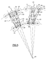
- la figure 5 est une vue de dessus du carrousel de la machine illustrant les deux positions relatives des dispositifs de traitement par rapport aux unités de préhension ;
- la figure 6 est une vue schématique de dessus d'une machine selon l'invention, agencée pour le réchauffage de préformes ou d'ébauches de récipients.
- Figure 1 is a schematic perspective view of the operating principle of a processing machine according to the invention;
- Figure 2 is a schematic top view of the machine according to the invention;
- Figure 3 illustrates a gripping unit of the containers;
- Figure 4 schematically illustrates a processing device for simultaneously processing two containers;
- Figure 5 is a top view of the carousel of the machine illustrating the two relative positions of the treatment devices with respect to the gripping units;
- Figure 6 is a schematic top view of a machine according to the invention, arranged for heating preforms or blanks containers.
Comme il sera exposé plus en détail, l'invention peut s'appliquer, par exemple, de façon tout à fait avantageuse aux machines destinée à rincer et désinfecter des récipients, notamment des bouteilles en polyéthylène téréphtalate (PET), en vue de leur remplissage avec un liquide qui peut être alimentaire, ou bien encore aux machines destinées à rincer et désinfecter des ébauches de tels récipients, appelées préformes.As will be explained in more detail, the invention can be applied by example, quite advantageous to the machines for rinsing and disinfect containers, especially polyethylene bottles terephthalate (PET), with a view to filling them with a liquid which can be food, or even machines intended to rinse and disinfect blanks of such containers, called preforms.
Elle peut encore s'appliquer de façon tout à fait intéressante dans les machines de fabrication de récipients par soufflage de telles préformes, plus précisément dans les fours de conditionnement thermique de telles préformes situés en amont des dispositifs de moulage par soufflage.It can still apply quite interestingly in blow molding machines such blow molding machines preforms, specifically in thermal conditioning furnaces such preforms located upstream of the molding devices blowing.
La description qui suit illustre plus spécialement le traitement d'objets constitués par des corps creux, tels que des récipients (bouteilles, flacons ou autres) ou des préformes de récipients.The following description illustrates more specifically the treatment objects consisting of hollow bodies, such as containers (bottles, bottles or other) or preforms of containers.
On a illustré sur les figures 1 et 2 le principe d'une machine de
traitement d'objets à la fois compacte et capable de hautes cadences.
Cette machine comporte une série de postes 12 qui effectuent un
cheminement en boucle. Dans l'exemple illustré, tous les postes 12 sont
solidaires d'un carrousel circulaire 10 qui est entraíné en rotation de
manière continue autour de son axe A0. Cependant, l'invention pourrait
aussi être mise en oeuvre dans le cadre de postes liés l'un à l'autre selon
le principe d'une chaíne sans fin d'entraínement.FIGS. 1 and 2 illustrate the principle of a machine for
treatment of objects both compact and capable of high rates.
This machine comprises a series of
Le principe de cette machine est de conserver chaque objet sur un poste respectif pendant une durée supérieure à celle nécessaire au poste pour effectuer un tour complet de son circuit de cheminement. En l'occurrence l'objet reste sur le poste pendant presque deux tours.The principle of this machine is to keep each object on a respective post for a period longer than that required by the post to complete a complete tour of his circuit. In the occurrence the object remains on the station for almost two turns.
La machine illustrée est donc une machine rotative dont l'axe de
rotation sera qualifié de vertical pour la clarté de la description. Le
carrousel 10 comporte une série de postes 12 qui sont répartis
angulairement autour de l'axe A0 et qui sont destinés chacun à porter
plusieurs bouteilles 11. Dans l'exemple illustré, chaque poste 12 peut
porter deux bouteilles. Toutefois, l'invention pourra aussi être mise en
oeuvre avec des postes pouvant chacun prendre en charge plus de
bouteilles.The illustrated machine is therefore a rotary machine whose axis of
rotation will be qualified as vertical for the sake of clarity. The
Chaque poste comporte une unité de préhension 14 de bouteilles qui
est mobile par rapport au poste, donc par rapport au carrousel, et qui
comporte en l'occurrence deux systèmes de préhension 16 pouvant chacun
prendre en charge une bouteille. Dans l'exemple, il s'agit de pinces qui
peuvent saisir une bouteille PET par le col, ces pinces étant de préférence
des pinces dont l'ouverture et la fermeture sont commandées par un
mécanisme spécifique, ce mécanisme devant éviter tout risque d'ouverture
intempestive de la pince lorsque la bouteille est en cours de traitement,
ces pinces permettant par ailleurs de laisser libre l'ouverture des bouteilles
afin de permettre l'introduction d'un produit de rinçage ou de nettoyage
lorsque la machine est destinée à de telles fonctions.Each station comprises a
Chaque unité de préhension 14 est montée mobile en rotation par
rapport à son poste 12 autour d'un axe An qui est tangent à la trajectoire
du poste. En l'occurrence, chaque unité de préhension est prévue pour
pouvoir occuper deux positions opposées à 180 degrés autour de l'axe An.
Cependant, dans le cas d'une unité de préhension comportant plus de deux
systèmes de préhension, on prévoira que l'unité peut occuper au moins
autant de positions discrètes différentes que l'unité peut porter de
bouteilles. Dans tous les cas, le nombre de positions pour une unité pourra
être supérieur au nombre de bouteilles.Each gripping
Les systèmes de préhension 16 sont agencés de telle sorte que les
bouteilles portées par une même unité sont disposées selon deux axes
verticaux parallèles, symétriquement de part et d'autre de l'axe An et les
bouteilles étant bien entendu en sens inverse l'une par rapport à l'autre.
Ainsi, lorsque l'une des bouteilles est orientée avec son extrémité ouverte
vers le haut, l'extrémité ouverte de l'autre bouteille est orientée vers le
bas.The gripping
Comme on peut le voir sur la figure 3, les pinces 16 sont décalées
selon la direction des axes des bouteilles et elles sont agencées de part et
d'autre de l'axe An de manière que celle qui porte la bouteille col en bas
est située au-dessous du niveau de celle qui porte la bouteille col en haut.
Par cette disposition, on diminue l'espace libre nécessaire au retournement
de l'unité de préhension lorsqu'elle porte les bouteilles.As can be seen in FIG. 3, the
Bien entendu, l'unité de préhension 14 est entièrement symétrique
par rapport à l'axe An. En raison de la géométrie de l'unité de préhension
14, chaque pince est amenée à se retrouver alternativement dans une
position radiale externe et dans une position radiale interne par rapport à
l'axe A0 du carrousel. Dans un cas, la bouteille qu'elle porte est orientée
col en bas, ici lorsque la pince est en position radiale externe. En position
radiale interne, elle est orientée col en haut. Quelle que soit la position de
l'unité de préhension 14, les axes des bouteilles sont tous sensiblement
dans un même plan radial contenant l'axe A0 de rotation du carrousel et
perpendiculaire à l'axe An de rotation de l'unité 14 considérée.Of course, the gripping
Sur les figures 1 et 2, on peut voir que des systèmes de convoyage
appropriés 15, de type connu, amènent les récipients 11 de manière
tangente jusqu'à un point de chargement du carrousel dont la position est
fixe autour de l'axe A0. En ce point, dans ce cas particulier d'une machine
de rinçage et de nettoyage, la bouteille est prise en charge, col en bas,
par la pince externe d'une unité de préhension. Au fur et à mesure de la
rotation du carrousel, à chaque passage par le point de chargement,
chaque poste prend en charge un récipient en le saisissant par la pince
qui, à cet instant, est en position radiale externe. Une fois prise en charge
par une unité de préhension 14, la bouteille est alors entraínée en rotation
autour de l'axe A0, par le carrousel, sur près d'un demi-tour, jusqu'à
arriver à un secteur de retournement.In FIGS. 1 and 2, it can be seen that
Au niveau de ce secteur de retournement, l'unité de préhension 14
est entraínée en rotation autour de son axe An sur 180 degrés. De cette
façon, la bouteille qui se trouvait initialement en position radiale externe
avec le col en bas subit un déplacement qui l'amène à une position radiale
interne avec le col en haut.At this turnaround sector, the gripping
Divers moyens peuvent permettre de commander ce retournement de
l'unité de préhension 16. Dans l'exemple illustré à la figure 3, on peut voir
que chaque unité de préhension 16 comporte deux bras 18 qui s'étendent
symétriquement dans un plan perpendiculaire à l'axe An. Chaque bras 18
présente une extrémité en U qui, au cours de la rotation du carrousel, est
destinée à suivre un profilé 20 fixe de la machine.Various means can make it possible to control this reversal of
the gripping
Le long des secteurs angulaires pour lesquels l'unité de préhension
16 reste fixe, les profilés sont agencés selon des arcs de cercles d'axe A0.
Au niveau du secteur de retournement, chaque profilé 20 s'étend selon un
tronçon d'une hélice enroulée sur une surface torique. Un tel moyen de
commander le retournement est analogue à celui décrit dans le document
EP-A-0.477.341 et on remarque que, ainsi commandée, l'unité de
traitement 14 tourne toujours dans le même sens autour de son axe An.
Toutefois, d'autres moyens pourront être utilisés, tels que des actionneurs
motorisés.Along the angular sectors for which the gripping
Dans l'exemple illustré, chaque unité de préhension 14 n'est amenée
à occuper que deux positions et on ne prévoit qu'un seul secteur de
retournement. De la sorte, une bouteille qui vient d'être prise en charge
sur le carrousel, et qui vient d'être retournée, est amenée à effectuer un
tour complet en position radiale interne. Dans le cadre d'un traitement de
nettoyage et de désinfection, cette durée permet de donner à l'agent
stérilisant un temps d'action suffisant. On pourrait toutefois envisager une
machine présentant par exemple trois secteurs de retournement. De même,
on pourrait prévoir d'amener l'unité de préhension dans un certain nombre
de positions intermédiaires.In the illustrated example, each gripping
Bien entendu, on pourrait encore prévoir d'amener les bouteilles col en haut et de les retourner pour les placer col en bas sur la machine.Of course, we could still plan to bring the bottles at the top and turn them over to place them neck down on the machine.
A l'issue de son tour en position radiale interne, la bouteille est de nouveau ramenée en position radiale externe par l'unité de préhension. Elle a alors effectué environ un tour et demi autour de l'axe A0 depuis son chargement sur le carrousel.At the end of its turn in the internal radial position, the bottle is again brought back to the outer radial position by the gripping unit. She then made about a turn and a half around the A0 axis since her loading on the carousel.
La rotation du carrousel se poursuivant, la bouteille considérée en
position radiale externe arrive jusqu'à un point de déchargement qui, dans
le sens de rotation, est situé juste avant le point de chargement. Au point
de déchargement, un système de convoyage 17 prélève les bouteilles,
libérant ainsi successivement les postes qui, en arrivant au point de
chargement, peuvent de nouveau prendre en charge une bouteille à traiter.The rotation of the carrousel continues, the bottle considered in
external radial position reaches a point of unloading which, in
the direction of rotation, is located just before the point of loading. On point
unloading, a conveying
Dans l'exemple décrit, l'unité de préhension n'occupe que deux positions discrètes distinctes. Aussi, les positions initiale de chargement et finale de déchargement d'une bouteille sont les mêmes. Toutefois, on pourrait envisager que ces deux positions de la bouteille soient différentes.In the example described, the gripping unit occupies only two discrete discrete positions. Also, the initial positions of loading and final unloading of a bottle are the same. However, could consider that these two positions of the bottle are different.
Grâce à cette conception de la machine, il est possible de faire subir à la bouteille un nettoyage et une désinfection complets entre le chargement et le déchargement, sans avoir à transférer la bouteille entre deux étapes de traitement. Ainsi, sans que la bouteille ne soit relâchée, elle peut subir successivement un premier rinçage, une désinfection par projection d'un agent stérilisant, et un rinçage final pour éliminer les traces d'agent stérilisant.Thanks to this design of the machine, it is possible to submit to the bottle a complete cleaning and disinfection between the loading and unloading, without having to transfer the bottle between two stages of treatment. Thus, without the bottle being released, it can successively undergo a first rinse, a disinfection by projection of a sterilizing agent, and a final rinse to eliminate traces sterilizing agent.
On comprend aisément que la durée relative des diverses étapes de traitement dépend aussi de l'emplacement du ou des secteurs de retournement par rapport au circuit. Ainsi, en partant de l'exemple illustré par les figures 1 et 2, il serait possible de réduire la durée du premier rinçage en disposant le secteur de retournement plus près du point de chargement des bouteilles. Corrélativement, la durée du rinçage final serait augmentée. A la limite, il pourrait n'être possible de réaliser que deux étapes de traitement en disposant le secteur de retournement immédiatement à proximité du point de chargement ou du point de déchargement.It is easy to understand that the relative duration of the various stages of treatment also depends on the location of the sector (s) of turnaround from the circuit. So, starting from the illustrated example in Figures 1 and 2, it would be possible to reduce the duration of the first rinsing by arranging the turning area closer to the point of loading bottles. Correlatively, the duration of the final rinse would be increased. At the limit, it may be possible to achieve only two stages of treatment by arranging the turning sector immediately near the point of loading or the point of unloading.
L'invention offre donc une grande souplesse.The invention therefore offers great flexibility.
Dans l'exemple décrit ci-dessus, chaque unité de préhension 14 ne
comporte que deux systèmes de préhension 16 si bien que chaque
récipient effectue une fraction de nombres de tour de carrousel comprise
entre 1 et 2. Pour une machine comportant quatre systèmes de préhension
par unité de préhension, chaque récipient pourrait effectuer sur le
carrousel entre 2 et 3 tours.In the example described above, each gripping
La machine selon l'invention comporte aussi des dispositifs de
traitement 22 aptes à projeter à l'intérieur de la bouteille des liquides, tels
que de l'eau ou un agent stérilisant. Eventuellement, on pourrait aussi
prévoir la projection d'un gaz, ou de tout autre agent. The machine according to the invention also comprises
Comme on peut le voir sur les figures 4 et 5, chaque dispositif
comporte deux becs de projection : un bec externe 24 qui est susceptible
de projeter, vers le haut, un agent de rinçage, ici du liquide, à l'intérieur
d'une bouteille disposée col en bas en position radiale externe, et un bec
interne 26 qui peut projeter, vers le bas, l'agent stérilisant à l'intérieur
d'une bouteille disposée col en haut en position radiale interne.As can be seen in FIGS. 4 and 5, each device
has two projection spouts: an
Sur la figure 5, on voit que chaque dispositif 22 est mobile entre une
position dégagée et une position active. En effet, chaque dispositif 22 est
agencé au sommet d'une colonne verticale 28 qui, par rapport à l'axe A0,
est située radialement entre le cercle externe et le cercle interne de la
trajectoire des bouteilles. Au sommet de la colonne 28, les deux becs 24,
26 sont montés à rotation autour de l'axe de la colonne 28, de préférence
par l'intermédiaire d'un raccord rotatif 30 qui permet de relier les becs 24,
26 à des circuits de distribution de produits 32 de la machine. Les deux
becs 24, 26 s'étendent à l'opposé l'un de l'autre par rapport à la colonne
28.In FIG. 5, it can be seen that each
Les dispositifs de traitement 22 sont en même nombre que les unités
de préhension 14 et ils sont intercalés angulairement entre les postes 12.
En position dégagée, les deux becs 24, 26 sont orientés sensiblement
dans un plan radial contenant l'axe A0 de manière à ne pas interférer avec
les unités de préhension 14 adjacentes, ni avec les bouteilles que celles-ci
portent. Dans cette position, ils n'entravent pas le retournement des
bouteilles. En position active, les deux becs ont pivoté autour de l'axe
vertical de la colonne 28, de telle sorte que le bec interne 26 soit en
regard de l'ouverture d'une bouteille en position radiale interne sur l'un
des deux postes adjacents au dispositif 22. Le bec externe 24 est alors en
regard de l'ouverture d'une bouteille en position radiale externe sur l'autre
des deux postes adjacents.The
En position active, un dispositif 22 peut donc traiter en même temps
deux bouteilles en projetant dans l'une du liquide de rinçage et dans
l'autre un agent stérilisant. Pour le bon fonctionnement de la machine, il
faut toutefois ramener le dispositif en position dégagée, d'une part au
niveau du secteur angulaire de renversement, et, d'autre part, au niveau
du secteur angulaire le long duquel se font le déchargement et le
chargement des bouteilles. In the active position, a
Comme on le voit sur la figure 4, le bec externe 24, qui projette du
liquide de rinçage dans une bouteille disposée col en bas, est reçu
coaxialement dans une conduite de récupération tubulaire 34 dont
l'extrémité ouverte est en regard du col de la bouteille lorsque le dispositif
est en position active. La conduite de récupération 34 peut ainsi récolter le
liquide de rinçage qui s'écoule de la bouteille et l'évacue, via le raccord
tournant 30, vers les circuits de distribution de la machine. Bien entendu,
le bec interne 24 et la conduite de récupération 34 sont solidaires l'un de
l'autre.As can be seen in FIG. 4, the
Par ailleurs, les dispositifs 22 comportent des moyens pour éviter de
projeter du produit sur la machine s'il n'y a pas de bouteille sur l'un des
postes. En effet, le bec externe 24 comporte un déflecteur mobile 36 qui,
lorsqu'il n'y a pas de bouteille, se trouve juste en regard du bec 24 et de la
conduite de récupération 34. Ainsi, le liquide projeté par le bec 24 est
renvoyé directement vers la conduite de récupération.Furthermore, the
Le déflecteur 36 est agencé à l'extrémité d'un bras 37 qui peut
pivoter par rapport au bec 24 et à la conduite 34 autour d'un axe vertical
parallèle à l'axe de pivotement de ces derniers. Lorsque le bec 24 passe
de sa position dégagée à sa position active, le déflecteur 36 est prévu
pour venir en appui sur le col de la bouteille, s'il y en a une. Dans ce cas,
le déflecteur 36 pivote par rapport au bec 24, lequel poursuit sa course
vers sa position active en regard de l'extrémité ouverte de la bouteille.
Ainsi, en présence d'une bouteille, le déflecteur est écarté du bec et ne
perturbe par la projection de liquide.The
Au contraire, en l'absence de bouteille, le déflecteur 36 ne rencontre
pas de surface d'appui et reste en regard du bec 24, ce qui est sa position
habituelle vers laquelle il est ramené par des moyens élastiques (non
représentés).On the contrary, in the absence of a bottle, the
De manière similaire, le bec interne 26 est équipé d'une tubulure de
récupération 38 qui, en l'absence de bouteille, se situe juste en regard du
bec 26. En présence d'une bouteille, la tubulure 38 est écartée en
pivotement par le col de la bouteille lorsque le dispositif 22 passe de sa
position dégagée à sa position active.Similarly, the
Ces deux dispositifs anti-projection sont entièrement mécaniques et sont donc particulièrement simples à mettre en oeuvre. Toutefois, on peut aussi prévoir de les remplacer par des dispositifs plus perfectionnés comportant des moyens de détection de la présence d'une bouteille et des moyens de vannage pour commander la projection de liquide en fonction de l'information fournie par les moyens de détection.These two anti-projection devices are entirely mechanical and are therefore particularly simple to implement. However, we can also plan to replace them with more sophisticated devices comprising means for detecting the presence of a bottle and valve means for controlling the projection of liquid according to information provided by the detection means.
Dans la machine illustrée sur les figures 1 à 5, on met donc à profit les positions initiales et finales du récipient, qui sont d'ailleurs identiques, pour lui faire subir des traitements, en l'occurrence des opérations de rinçage. La durée de ces opérations est suffisante grâce au fait que le récipient reste dans ces deux positions pendant près de la moitié d'un tour du carrousel.In the machine illustrated in FIGS. 1 to 5, it is therefore useful to the initial and final positions of the container, which are identical, to undergo treatment, in this case rinsing. The duration of these operations is sufficient thanks to the fact that container stays in these two positions for almost half a turn carousel.
La machine ainsi proposée est donc particulièrement simple et compacte, tout en permettant de mettre en oeuvre un procédé complet de nettoyage et de stérilisation du récipient.The machine thus proposed is therefore particularly simple and compact, while allowing to implement a complete process of cleaning and sterilization of the container.
Comme ceci a été évoqué, l'invention trouve une autre application particulièrement avantageuse pour le réchauffage de préformes ou d'ébauches de récipients dans les installations de fabrication de récipients en matière plastique, par soufflage ou étirage puis soufflage de telles préformes ou ébauches.As has been mentioned, the invention finds another application particularly advantageous for heating preforms or of blanks for containers in container-making plants made of plastic, by blowing or stretching and then blowing such preforms or blanks.
La figure 6 en est une illustration schématique.Figure 6 is a schematic illustration.
Comme sur les figures 1 et 2, la machine comporte une série de
postes 120 qui effectuent un cheminement en boucle. Dans l'exemple
illustré, tous les postes 120 sont solidaires d'un carrousel circulaire 100
qui est entraíné en rotation de manière continue autour de son axe A10
vertical. Cependant, l'invention pourrait aussi être mise en oeuvre dans le
cadre de postes liés l'un à l'autre selon le principe d'une chaíne à maillons.As in Figures 1 and 2, the machine has a series of
120 stations that perform a looping path. In the example
illustrated, all the
Les postes 120 qui sont répartis angulairement autour de l'axe A10
et sont destinés chacun à porter plusieurs, dans l'exemple illustré deux,
préformes 110 ou ébauches de récipientsThe
Chaque poste comporte une unité de préhension 140 de préformes
110 ou d'ébauches de récipients qui est mobile par rapport au poste, donc
par rapport au carrousel, et qui comporte en l'occurrence deux systèmes
de préhension 160 pouvant chacun prendre en charge une préforme 110 ou
ébauche de récipient. Chaque système de préhension 160 comporte d'une
part des moyens de saisie, non illustrés en détail, mais connus en soi,
d'une préforme 110 ou ébauche de récipient, et des moyens pour permettre
la rotation des préformes 110 autour de leur axe longitudinal au moins
lorsque les préformes sont dans une zone de réchauffage. Each station comprises a
Ainsi, les moyens de saisie sont par exemple constitués par des mécanismes de type mandrin qui saisissent l'intérieur ou l'extérieur du col des préformes, et les moyens pour mettre en rotation les préformes sur elles-mêmes sont liés mécaniquement aux moyens de saisie. La mise en rotation s'effectue par exemple à l'aide de mécanismes à chaínes et pignons, connus en soi et non représentés.Thus, the input means are for example constituted by mandrel-type mechanisms that grip the inside or outside of the neck preforms, and the means for rotating the preforms on they themselves are mechanically linked to the input means. Setting rotation is for example using chain mechanisms and sprockets, known per se and not shown.
Comme pour les applications destinées au rinçage et au nettoyage
de récipients, illustrées sur les figures 1 à 5, chaque unité de préhension
140 est montée mobile en rotation par rapport à son poste 120 autour d'un
axe qui est tangent à la trajectoire du poste. Dans l'exemple, chaque unité
de préhension est prévue pour pouvoir occuper deux positions opposées à
180 degrés autour de cet axe.As for rinsing and cleaning applications
of containers, illustrated in Figures 1 to 5, each
L'unité de préhension 140 est symétrique par rapport à l'axe tangent
à la trajectoire du poste. En raison de la géométrie de l'unité de
préhension 140, chaque préforme est amenée à se retrouver
alternativement orientée dans une position col en bas et dans une position
col en haut.The
Des systèmes de convoyage appropriés 150, de type connu, amènent
les préformes 110 ou ébauches de récipients, col en haut, de manière
tangente jusqu'à un point de chargement du carrousel dont la position est
fixe autour de l'axe A10. En ce point, chaque préforme est prise en charge,
par les moyens de saisie d'une unité de préhension. Au fur et à mesure de
la rotation du carrousel, à chaque passage par le point de chargement,
chaque poste prend en charge une préforme 110. Une fois prise en charge
par une unité de préhension 140, chaque préforme 110 est alors entraínée
en rotation autour de l'axe A10, par le carrousel, sur près d'un, demi-tour
dans l'exemple illustré, jusqu'à, arriver à un secteur de retournement.
Au niveau de ce secteur de retournement, l'unité de préhension 140
est entraínée en rotation autour de son axe tangent à la trajectoire du
poste sur 180 degrés. De cette façon, la préforme qui se trouvait
initialement en position avec le col en haut subit un déplacement qui
l'amène à une position radiale interne avec le col en bas.At this turnaround sector, the
Des moyens similaires ou identiques à ceux décrits en regard des figures 1 à 5, tels que des profilés, peuvent être utilisés pour assurer le retournement, toujours dans le même sens, d'une part et le maintien en position fixe des unités de préhension d'autre part. Ils ne seront donc pas décrits plus en détail.Means similar or identical to those described with regard to FIGS. 1 to 5, such as profiles, can be used to ensure the reversal, always in the same direction, on the one hand and the maintenance in fixed position of the gripping units on the other hand. They will not be described in more detail.
Dans l'exemple illustré, chaque unité de préhension 140 n'est
amenée à occuper que deux positions et on ne prévoit qu'un seul secteur
de retournement.In the illustrated example, each
A l'issue de son tour en position col en bas, la préforme est de nouveau ramenée en position col en haut par l'unité de préhension. Elle a alors effectué environ un tour et demi autour de l'axe A10 depuis son chargement sur le carrousel.At the end of its turn in the neck down position, the preform is again brought back to the neck position at the top by the gripping unit. She has then performed about a turn and a half around the A10 axis since his loading on the carousel.
La rotation du carrousel se poursuivant, la préforme considérée en
position col en haut arrive jusqu'à un point de déchargement où un
système de convoyage 170 prélève chaque préforme, et l'entraíne vers un
moule de soufflage, non représenté, libérant ainsi successivement les
postes qui, en arrivant au point de chargement, peuvent de nouveau
prendre en charge une préforme à réchauffer.The rotation of the carousel continues, the preform considered in
col top position comes up to an unloading point where a
conveying
Dans l'exemple décrit, puisque l'unité de préhension n'occupe que deux positions discrètes distinctes, les positions initiale de chargement et finale de déchargement d'une préforme sont les mêmes. Toutefois, on pourrait envisager que ces d'eux positions de la préforme soient différentes, notamment dans les installations dans lesquelles les préformes sont introduites col en haut, et le soufflage des récipients s'effectue avec le col en bas.In the example described, since the gripping unit only occupies two discrete discrete positions, the initial positions of loading and final unloading of a preform are the same. However, could consider that these of their preform positions are different, especially in installations in which preforms are introduced neck up, and the blowing of the containers is done with the collar down.
Dans cette application, le traitement consiste en un réchauffage des
préformes 110, et des dispositifs de traitement 220, 221, constitués par
des moyens de réchauffage des préformes 110, dont la structure est
connue en soi, sont fixés au châssis de la machine et sont disposés de
façon appropriée dans les zones comprises entre la zone de chargement
150 et la zone de retournement d'une part, de même qu'entre la zone de
retournement et la zone de déchargement d'autre part, de façon à chauffer
les préformes qui passent en regard de ces moyens, qu'elles se trouvent
avec leur col en haut ou en bas. A titre d'exemple, ces moyens de
réchauffage sont constitués par des lampes et des réflecteurs.In this application, the treatment consists of reheating of
Grâce à cette conception de la machine, et avec l'exemple illustré où les postes peuvent prendre deux positions, le réchauffage s'effectue en deux tours de carrousel, et on conçoit aisément qu'il est possible de réduire la circonférence du carrousel dans un rapport d'approximativement deux pour arriver au même résultat, en termes de cadences et d'efficacité, qu'avec une machine classique. On parvient donc à réduire considérablement l'encombrement d'une installation de fabrication de récipients.Thanks to this design of the machine, and with the illustrated example where the positions can take two positions, the reheating takes place in two carousel towers, and it is easy to imagine that it is possible to reduce the circumference of the carousel in a ratio of approximately two to achieve the same result, in terms of rates and efficiency, than with a conventional machine. It is therefore possible to reduce considerably the size of a manufacturing facility containers.
On comprend aisément que la durée relative des diverses étapes de chauffage dépend de l'emplacement du ou des secteurs de retournement par rapport au circuit. Dans l'exemple, les préformes effectuent, après leur chargement, presque un demi-tour de circuit où elles sont réchauffées col en haut, puis un tour col en bas, et enfin presque un demi-tour à nouveau col en haut. Toutefois, il serait possible de réduire la durée du premier réchauffage col en haut en disposant le secteur de retournement plus près du point de chargement des préformes ; alternativement, il serait possible de réduire la durée du dernier réchauffage col en haut en disposant le secteur de retournement plus près du point de déchargement des préformes.It is easy to understand that the relative duration of the various stages of Heating depends on the location of the turning sector (s) compared to the circuit. In the example, the preforms perform, after their loading, almost a half-circuit circuit where they are warmed up at the top, then a neck down turn, and finally almost a half turn again collar at the top. However, it would be possible to reduce the duration of the first reheating collar up by arranging the turning area closer the loading point of the preforms; alternatively, it would be possible to reduce the duration of the last reheat collar up by laying out the turning sector closer to the point of unloading preforms.
A la limite, il pourrait n'être possible de réaliser que deux étapes de réchauffage en disposant le secteur de retournement immédiatement à proximité du point de chargement ou du point de déchargement. Dans ce cas, selon l'option choisie; le réchauffage commencerait col en bas ou col en haut ; de plus, dans ce cas, il n'y aurait plus de moyens de réchauffage dans la zone comprise entre le point de chargement et le secteur de retournement ou dans celle comprise entre le secteur de retournement et le point de déchargement.At the limit, it may be possible to achieve only two stages of reheat by arranging the turnaround area immediately to near the point of loading or the point of unloading. In this case, depending on the option chosen; warming up would start neck down or collar up ; moreover, in this case, there would be no more means of reheating in the area between the point of loading and the area of reversal or in that between the turning sector and the point of unloading.
L'invention est donc particulièrement avantageuse dans ce type particulier d'application, puisqu'elle permet de réduire l'emprise au sol des fours de réchauffage ; en outre, elle permet d'optimiser le réchauffage grâce aux possibilités de mise en position des préformes col en haut ou col en bas.The invention is therefore particularly advantageous in this type particular application, since it makes it possible to reduce the footprint of reheating furnaces; in addition, it optimizes the heating thanks to the positioning possibilities of the neck or collar preforms below.
Claims (21)
- Machine for treating objects (11; 110), particularly hollow bodies such as containers or container preforms, of the type comprising a series of workstations (12; 120) which can move in a path on a loop-shaped circuit and each of which comprises a grasping system (16; 160) intended to grip an object (11; 110) at a loading point and return it at an unloading point in the path, of the type in which, between the loading and unloading points, the object (11; 110) is moved relative to the workstation (12; 120) by the gripping system (16; 160) from an initial loading position to at least one treatment position and then to a final unloading position, of the type in which the machine comprises treatment devices (22; 220; 221) for treating the objects grasped by each workstation, of the type in which each workstation is equipped with a gripping unit (14; 140) comprising at least two gripping systems (16; 160), and of the type in which the gripping unit (14; 140) is able to move with respect to the workstation between at least a first position, for which a first object carried by a first system (16; 160) of the unit (14; 140) is in its initial position while a second object carried by a second system (16; 160) of the unit (14; 140) is in a treatment position, and a last position for which the first object is in a treatment position while the second object is in its final position, characterized in that, between the loading and the unloading of an object, the path followed by said object involves a number of passes round the circuit which number is comprised between the number of gripping systems (16; 160) of each treatment unit (14; 140) and the integer immediately below.
- Treatment machine according to Claim 1, characterized in that, at each pass past the loading point, each gripping unit (14; 140) is capable of picking up one object.
- Treatment machine according to either one of the preceding claims, characterized in that each gripping unit (14; 140) is able to move in rotation with respect to the associated workstation (12; 120) about an axis (An) tangential at a given point to the direction of the path of the workstation (12; 120) at this point.
- Treatment machine according to any one of the preceding claims, characterized in that each gripping unit (14; 140) is able to move sequentially between at least as many discrete positions as each gripping unit (14; 140) has gripping systems (16; 160).
- Treatment machine according to any one of Claims 1 to 4, characterized in that the initial and final positions of each object (11; 110) with respect to the workstation carrying it are identical.
- Treatment machine according to any one of Claims 1 to 5, characterized in that the workstations (12; 120) are secured to a drive device consisting of a rotary carousel (10; 100) of the machine.
- Treatment machine according to any one of Claims 1 to 5, characterized in that the workstations (12; 120) are secured to a drive device consisting of an endless chain.
- Treatment machine according to one of Claims 6 and 7, characterized in that it is intended for treating containers (11) and in that each gripping unit (14) comprises two gripping systems (16) each of which carries a container more or less via its open end, in that the containers are arranged in opposite directions along two parallel axes contained in a radial plane of the drive device and which are offset on each side of the axis of rotation (An) of the unit (14), and in that the positions of the two containers in the direction of their axes partially overlap.
- Treatment machine according to Claim 8, characterized in that, in the initial position and in the final position, the containers are in a vertical position with the open end downwards so as to undergo a first and a last rinsing treatment.
- Treatment machine according to one of Claims 8 and 9, characterized in that, in the treatment position, the containers are in a vertical position with the open end upwards in order to undergo an intermediate cleaning treatment during which a cleaning product is injected into the container.
- Treatment machine according to any one of Claims 1 to 10, characterized in that the treatment devices (22) follow the path of the workstations (12) and in that each device (22) is able to move with respect to the adjacent workstations (12) between a clear position and an active position in which it is able to collaborate with at least one of the objects carried by one of the gripping units (14).
- Treatment machine according to Claim 11, characterized in that each treatment device (22) comprises at least two treatment means (24, 26) intended each to collaborate with one object, the two objects being carried respectively by two adjacent workstations (12).
- Treatment machine according to Claims 5 and 12 taken in combination, characterized in that the treatment devices (22) are able to move in rotation with respect to the carousel (10; 100) about an axis more or less parallel to the axis (A0) of rotation of the carousel.
- Treatment machine according to Claim 13, characterized in that the gripping units (14) and the treatment devices (22) are arranged more or less on one and the same circle about the axis of rotation (A0) of the carousel, and in that each treatment device (22) is interposed between two adjacent gripping units (14), and in that, in the active position, each treatment device (22) collaborates with objects from the two adjacent units flanking it.
- Treatment machine according to Claims 6 and 12 taken in combination, characterized in that the treatment devices (22) are able to move in rotation with respect to the endless chain about an axis more or less perpendicular to the main plane of the endless chain.
- Treatment machine according to Claim 15, characterized in that the gripping units (14) and the treatment devices (22) are arranged in alternation on the endless chain such that each treatment device (22) is interposed between two adjacent gripping units (14) and in that, in the active position, each treatment device (22) collaborates with objects of the two adjacent units which flank it.
- Treatment machine according to any one of Claims 12 to 16, characterized in that it is intended for the treatment of containers (11), and the treatment devices (22) each comprise at least one tip (24) for spraying a rinsing fluid and a tip (26) for spraying a cleaning product towards the containers.
- Treatment machine according to one of Claims 1 to 10, characterized in that treatment devices (220; 221) are fixed to the chassis of the machine and are arranged facing the areas travelled by the objects as they are conveyed.
- Treatment machine according to Claim 18, characterized in that it comprises an object loading zone and an object unloading zone, at least one zone for changing the position of the gripping units (140) between the loading and unloading zones, and the treatment devices (220; 221) are arranged between the object loading zone and a zone for changing the position of the gripping units (140) and/or between a zone for changing the position of the gripping units (140) and the unloading zone.
- Treatment machine according to Claim 19, characterized in that it comprises at least two zones for changing the position of the gripping units (140) between the loading and unloading zones and in that treatment devices (220; 221) are interposed between at least two successive zones for changing the position of the gripping units (140).
- Treatment machine according to one of Claims 18 to 20, characterized in that it is intended for heating container preforms (110), and treatment devices (220; 221) consist of means for heating the said preforms.
Applications Claiming Priority (3)
| Application Number | Priority Date | Filing Date | Title |
|---|---|---|---|
| FR9908209A FR2795350B1 (en) | 1999-06-28 | 1999-06-28 | CONTAINER PROCESSING MACHINE |
| FR9908209 | 1999-06-28 | ||
| PCT/FR2000/001799 WO2001000340A1 (en) | 1999-06-28 | 2000-06-28 | Machine for treating objects |
Publications (2)
| Publication Number | Publication Date |
|---|---|
| EP1200208A1 EP1200208A1 (en) | 2002-05-02 |
| EP1200208B1 true EP1200208B1 (en) | 2005-09-07 |
Family
ID=9547358
Family Applications (1)
| Application Number | Title | Priority Date | Filing Date |
|---|---|---|---|
| EP00946030A Expired - Lifetime EP1200208B1 (en) | 1999-06-28 | 2000-06-28 | Machine for treating objects |
Country Status (14)
| Country | Link |
|---|---|
| US (1) | US6945260B1 (en) |
| EP (1) | EP1200208B1 (en) |
| JP (1) | JP3744853B2 (en) |
| KR (1) | KR100436344B1 (en) |
| CN (1) | CN1362897A (en) |
| AT (1) | ATE303873T1 (en) |
| AU (1) | AU775468B2 (en) |
| BR (1) | BR0011923B1 (en) |
| CA (1) | CA2376736C (en) |
| DE (1) | DE60022518T2 (en) |
| ES (1) | ES2246871T3 (en) |
| FR (1) | FR2795350B1 (en) |
| MX (1) | MXPA01013331A (en) |
| WO (1) | WO2001000340A1 (en) |
Families Citing this family (21)
| Publication number | Priority date | Publication date | Assignee | Title |
|---|---|---|---|---|
| DE20312210U1 (en) * | 2003-08-07 | 2004-09-16 | Krones Ag | Container handling machine |
| JP4983092B2 (en) * | 2005-06-21 | 2012-07-25 | 澁谷工業株式会社 | Electron beam sterilizer |
| DE102005032175A1 (en) * | 2005-07-09 | 2007-01-18 | Krones Ag | Container handling machine and method for loading and unloading a container handling machine |
| FR2892652B1 (en) * | 2005-10-28 | 2009-06-05 | Sidel Sas | ROTARY PROCESSING MACHINE FOR CONTAINERS |
| DE102006028266A1 (en) | 2006-06-20 | 2007-12-27 | Khs Ag | Method for treating containers and container treatment machine |
| JP4378655B2 (en) * | 2007-03-07 | 2009-12-09 | 株式会社ダイフク | Article processing equipment |
| DE102008032123A1 (en) | 2008-07-08 | 2010-01-14 | Krones Ag | Device for transporting containers with cooling for the containers |
| DE102008052614A1 (en) * | 2008-10-21 | 2010-05-27 | Khs Ag | Device for pivoting a bottle conveyed in a gripper |
| US8024069B2 (en) * | 2009-01-28 | 2011-09-20 | Ge Intelligent Platforms, Inc. | System and method for path planning |
| DE102009040559A1 (en) * | 2009-09-08 | 2011-03-10 | Krones Ag | Method and apparatus for blow molding containers |
| US8287270B2 (en) * | 2009-09-30 | 2012-10-16 | Printpack Illinois Inc. | Methods and systems for thermoforming with billets |
| DE102010008387B4 (en) * | 2010-02-17 | 2017-10-19 | Khs Gmbh | Device for transporting bottles or similar containers |
| EP2447172A1 (en) * | 2010-11-02 | 2012-05-02 | Stefano Boido | Apparatus for heating containers |
| JP6004161B2 (en) * | 2012-05-17 | 2016-10-05 | サントリーホールディングス株式会社 | Container processing equipment |
| KR101459329B1 (en) * | 2013-02-13 | 2014-11-12 | 종 해 김 | Apparatus for Multistory Filling and Capping System |
| DE102013105688B4 (en) * | 2013-06-03 | 2021-02-11 | Krones Ag | Oven for heating plastic preforms with multiple circulation of the plastic preforms |
| DE102014102116A1 (en) | 2014-02-19 | 2015-08-20 | Krones Ag | Apparatus for treating containers |
| DE102019127998A1 (en) | 2019-10-17 | 2021-04-22 | Krones Ag | Device and method for transporting objects |
| CN112958553B (en) * | 2021-01-26 | 2023-01-13 | 张晓霞 | Foldable bathing barrel body cleaning device |
| CN115504424A (en) * | 2022-10-31 | 2022-12-23 | 江西修江王酒业有限公司 | White spirit filling equipment and method |
| CN117654970A (en) * | 2024-02-01 | 2024-03-08 | 谱为科技(常州)有限公司 | Automatic needle cylinder cleaning equipment and working method thereof |
Family Cites Families (16)
| Publication number | Priority date | Publication date | Assignee | Title |
|---|---|---|---|---|
| US740793A (en) * | 1902-12-17 | 1903-10-06 | Jacob L Barrick | Machine for washing molds. |
| US838927A (en) * | 1906-08-27 | 1906-12-18 | Dennis Wickham | Bottle-soaking machine. |
| US1919965A (en) * | 1930-02-27 | 1933-07-25 | Borden Co | Apparatus for washing cans and the like |
| US3143218A (en) * | 1961-09-08 | 1964-08-04 | Ajem Lab Inc | Article handling apparatus and method |
| US3521650A (en) * | 1966-07-27 | 1970-07-28 | Ionic International Inc | Barrel-type processing apparatus |
| JPS5911852B2 (en) * | 1975-03-20 | 1984-03-19 | 旭光学工業 (株) | Exposure information quantization circuit using shift registers |
| US4074654A (en) * | 1976-01-06 | 1978-02-21 | Takeda Chemical Industries, Ltd. | Automatic closure cleansing and coating machine |
| CH596955A5 (en) * | 1976-07-13 | 1978-03-31 | Fischer Ag Georg | |
| US4104081A (en) * | 1976-08-09 | 1978-08-01 | Adolph Coors Company | In-line bottle rinser |
| US4259999A (en) | 1978-12-15 | 1981-04-07 | Shibuya Kogyo Company, Ltd. | Gas precharged, liquid filling machine operating with dual rows of containers |
| ES293164Y (en) * | 1986-03-24 | 1989-02-16 | Embomak, S.A. | PERFECTED SANITIZER FOR BOTTLES. |
| SE459730B (en) * | 1987-12-04 | 1989-07-31 | Kabivitrum Ab | APPLIANCES FOR FILLING AND CLOSING BOTTLES CONTAINING A NUMBER OF TREATMENT STATIONS PROVIDED IN A CYCLIC CYCLE |
| FR2660884B1 (en) * | 1990-04-11 | 1994-01-14 | Rene Perrier | DEVICE AND MACHINE FOR TREATING BOTTLES. |
| US5425385A (en) * | 1993-07-12 | 1995-06-20 | Pepsico. Inc. | Rotary washer spraying system |
| EP0721808B1 (en) * | 1994-12-16 | 1999-01-27 | Hermann Kronseder | Cleaning machine for containers |
| DE29606053U1 (en) * | 1996-04-01 | 1997-07-31 | C M S S P A Uffici Commerciali | Recovery device |
-
1999
- 1999-06-28 FR FR9908209A patent/FR2795350B1/en not_active Expired - Fee Related
-
2000
- 2000-06-28 MX MXPA01013331A patent/MXPA01013331A/en active IP Right Grant
- 2000-06-28 DE DE60022518T patent/DE60022518T2/en not_active Expired - Lifetime
- 2000-06-28 AU AU59927/00A patent/AU775468B2/en not_active Ceased
- 2000-06-28 US US10/018,342 patent/US6945260B1/en not_active Expired - Fee Related
- 2000-06-28 BR BRPI0011923-7A patent/BR0011923B1/en not_active IP Right Cessation
- 2000-06-28 JP JP2001506039A patent/JP3744853B2/en not_active Expired - Fee Related
- 2000-06-28 AT AT00946030T patent/ATE303873T1/en not_active IP Right Cessation
- 2000-06-28 WO PCT/FR2000/001799 patent/WO2001000340A1/en active IP Right Grant
- 2000-06-28 ES ES00946030T patent/ES2246871T3/en not_active Expired - Lifetime
- 2000-06-28 CA CA002376736A patent/CA2376736C/en not_active Expired - Fee Related
- 2000-06-28 CN CN00809732A patent/CN1362897A/en active Pending
- 2000-06-28 KR KR10-2001-7016526A patent/KR100436344B1/en not_active IP Right Cessation
- 2000-06-28 EP EP00946030A patent/EP1200208B1/en not_active Expired - Lifetime
Also Published As
| Publication number | Publication date |
|---|---|
| FR2795350B1 (en) | 2002-04-26 |
| WO2001000340A1 (en) | 2001-01-04 |
| US6945260B1 (en) | 2005-09-20 |
| JP3744853B2 (en) | 2006-02-15 |
| AU5992700A (en) | 2001-01-31 |
| ATE303873T1 (en) | 2005-09-15 |
| FR2795350A1 (en) | 2000-12-29 |
| CA2376736A1 (en) | 2001-01-04 |
| JP2003503179A (en) | 2003-01-28 |
| CN1362897A (en) | 2002-08-07 |
| DE60022518D1 (en) | 2005-10-13 |
| BR0011923A (en) | 2002-03-19 |
| ES2246871T3 (en) | 2006-03-01 |
| KR20020025085A (en) | 2002-04-03 |
| KR100436344B1 (en) | 2004-06-19 |
| CA2376736C (en) | 2007-06-12 |
| EP1200208A1 (en) | 2002-05-02 |
| BR0011923B1 (en) | 2008-11-18 |
| MXPA01013331A (en) | 2002-08-20 |
| DE60022518T2 (en) | 2006-06-22 |
| AU775468B2 (en) | 2004-08-05 |
Similar Documents
| Publication | Publication Date | Title |
|---|---|---|
| EP1200208B1 (en) | Machine for treating objects | |
| EP3239079B1 (en) | Facility for handling hollow bodies, comprising a distribution conveyor and satellite treatment units | |
| CA2214099C (en) | Apparatus for making containers by blow-moulding plastic parisons | |
| CA2164945C (en) | Plastic preform container blowring and fabricating plant | |
| EP0640035B1 (en) | Machine for blow moulding hollow objects | |
| CA2424866C (en) | Device for inverting a hollow body | |
| FR2802191A1 (en) | DEVICE FOR CONVEYING DISCRETE ENTITIES INCLUDING AN IMPROVED TRANSFER ARM AND INSTALLATION FOR BLOWING CONTAINERS PROVIDED WITH SUCH A DEVICE | |
| FR2691401A1 (en) | Unit for thermal treatment of PET containers during manufacture thereof. | |
| WO2006095099A1 (en) | Device for gripping the neck of hollow bodies and hollow body transport installation which is equipped with such devices | |
| EP2051918B1 (en) | Container inverting device | |
| EP2885230B1 (en) | Installation for treating articles comprising a transfer screw device | |
| EP1204524B1 (en) | Machines for blowing containers with built-on handles comprising an improved transfer arm | |
| WO1999003513A1 (en) | Installation for sterilising preforms of thermoplastic containers on a conveyor | |
| FR2796591A1 (en) | Blow moulding apparatus, for making bottles, etc., with handle from preform and separate handle having transfer arm, supplying preform and handle to mould cavity | |
| FR3070970A1 (en) | CONTAINER PROCESSING FACILITY | |
| EP1660371B1 (en) | Thermoplastic bottle-forming and -filling method and installation | |
| BE641423A (en) | ||
| JP2024056450A (en) | Open/close gripper | |
| DE102007057965A1 (en) | Apparatus for treating containers | |
| JP2000313499A (en) | Container treatment device |
Legal Events
| Date | Code | Title | Description |
|---|---|---|---|
| PUAI | Public reference made under article 153(3) epc to a published international application that has entered the european phase |
Free format text: ORIGINAL CODE: 0009012 |
|
| 17P | Request for examination filed |
Effective date: 20020128 |
|
| AK | Designated contracting states |
Kind code of ref document: A1 Designated state(s): AT BE CH CY DE DK ES FI FR GB GR IE IT LI LU MC NL PT SE |
|
| AX | Request for extension of the european patent |
Free format text: AL;LT;LV;MK;RO;SI |
|
| RAP1 | Party data changed (applicant data changed or rights of an application transferred) |
Owner name: SIDEL |
|
| 17Q | First examination report despatched |
Effective date: 20040219 |
|
| GRAP | Despatch of communication of intention to grant a patent |
Free format text: ORIGINAL CODE: EPIDOSNIGR1 |
|
| GRAS | Grant fee paid |
Free format text: ORIGINAL CODE: EPIDOSNIGR3 |
|
| GRAA | (expected) grant |
Free format text: ORIGINAL CODE: 0009210 |
|
| AK | Designated contracting states |
Kind code of ref document: B1 Designated state(s): AT BE CH CY DE DK ES FI FR GB GR IE IT LI LU MC NL PT SE |
|
| PG25 | Lapsed in a contracting state [announced via postgrant information from national office to epo] |
Ref country code: FI Free format text: LAPSE BECAUSE OF FAILURE TO SUBMIT A TRANSLATION OF THE DESCRIPTION OR TO PAY THE FEE WITHIN THE PRESCRIBED TIME-LIMIT Effective date: 20050907 Ref country code: AT Free format text: LAPSE BECAUSE OF FAILURE TO SUBMIT A TRANSLATION OF THE DESCRIPTION OR TO PAY THE FEE WITHIN THE PRESCRIBED TIME-LIMIT Effective date: 20050907 Ref country code: NL Free format text: LAPSE BECAUSE OF FAILURE TO SUBMIT A TRANSLATION OF THE DESCRIPTION OR TO PAY THE FEE WITHIN THE PRESCRIBED TIME-LIMIT Effective date: 20050907 Ref country code: IE Free format text: LAPSE BECAUSE OF FAILURE TO SUBMIT A TRANSLATION OF THE DESCRIPTION OR TO PAY THE FEE WITHIN THE PRESCRIBED TIME-LIMIT Effective date: 20050907 |
|
| REG | Reference to a national code |
Ref country code: GB Ref legal event code: FG4D Free format text: NOT ENGLISH |
|
| REG | Reference to a national code |
Ref country code: CH Ref legal event code: EP |
|
| REG | Reference to a national code |
Ref country code: IE Ref legal event code: FG4D Free format text: LANGUAGE OF EP DOCUMENT: FRENCH |
|
| REF | Corresponds to: |
Ref document number: 60022518 Country of ref document: DE Date of ref document: 20051013 Kind code of ref document: P |
|
| GBT | Gb: translation of ep patent filed (gb section 77(6)(a)/1977) |
Effective date: 20051104 |
|
| REG | Reference to a national code |
Ref country code: CH Ref legal event code: NV Representative=s name: KELLER & PARTNER PATENTANWAELTE AG |
|
| PG25 | Lapsed in a contracting state [announced via postgrant information from national office to epo] |
Ref country code: GR Free format text: LAPSE BECAUSE OF FAILURE TO SUBMIT A TRANSLATION OF THE DESCRIPTION OR TO PAY THE FEE WITHIN THE PRESCRIBED TIME-LIMIT Effective date: 20051207 Ref country code: DK Free format text: LAPSE BECAUSE OF FAILURE TO SUBMIT A TRANSLATION OF THE DESCRIPTION OR TO PAY THE FEE WITHIN THE PRESCRIBED TIME-LIMIT Effective date: 20051207 Ref country code: SE Free format text: LAPSE BECAUSE OF FAILURE TO SUBMIT A TRANSLATION OF THE DESCRIPTION OR TO PAY THE FEE WITHIN THE PRESCRIBED TIME-LIMIT Effective date: 20051207 |
|
| NLV1 | Nl: lapsed or annulled due to failure to fulfill the requirements of art. 29p and 29m of the patents act | ||
| REG | Reference to a national code |
Ref country code: ES Ref legal event code: FG2A Ref document number: 2246871 Country of ref document: ES Kind code of ref document: T3 |
|
| REG | Reference to a national code |
Ref country code: IE Ref legal event code: FD4D |
|
| PGFP | Annual fee paid to national office [announced via postgrant information from national office to epo] |
Ref country code: CH Payment date: 20060529 Year of fee payment: 7 |
|
| PG25 | Lapsed in a contracting state [announced via postgrant information from national office to epo] |
Ref country code: BE Free format text: LAPSE BECAUSE OF NON-PAYMENT OF DUE FEES Effective date: 20060630 Ref country code: MC Free format text: LAPSE BECAUSE OF NON-PAYMENT OF DUE FEES Effective date: 20060630 |
|
| PLBE | No opposition filed within time limit |
Free format text: ORIGINAL CODE: 0009261 |
|
| STAA | Information on the status of an ep patent application or granted ep patent |
Free format text: STATUS: NO OPPOSITION FILED WITHIN TIME LIMIT |
|
| 26N | No opposition filed |
Effective date: 20060608 |
|
| BERE | Be: lapsed |
Owner name: SIDEL Effective date: 20060630 |
|
| REG | Reference to a national code |
Ref country code: CH Ref legal event code: PL |
|
| PG25 | Lapsed in a contracting state [announced via postgrant information from national office to epo] |
Ref country code: CH Free format text: LAPSE BECAUSE OF NON-PAYMENT OF DUE FEES Effective date: 20070630 Ref country code: LI Free format text: LAPSE BECAUSE OF NON-PAYMENT OF DUE FEES Effective date: 20070630 |
|
| PG25 | Lapsed in a contracting state [announced via postgrant information from national office to epo] |
Ref country code: LU Free format text: LAPSE BECAUSE OF NON-PAYMENT OF DUE FEES Effective date: 20060628 |
|
| PG25 | Lapsed in a contracting state [announced via postgrant information from national office to epo] |
Ref country code: CY Free format text: LAPSE BECAUSE OF FAILURE TO SUBMIT A TRANSLATION OF THE DESCRIPTION OR TO PAY THE FEE WITHIN THE PRESCRIBED TIME-LIMIT Effective date: 20050907 |
|
| PGFP | Annual fee paid to national office [announced via postgrant information from national office to epo] |
Ref country code: GB Payment date: 20140527 Year of fee payment: 15 |
|
| PGFP | Annual fee paid to national office [announced via postgrant information from national office to epo] |
Ref country code: PT Payment date: 20140616 Year of fee payment: 15 Ref country code: ES Payment date: 20140617 Year of fee payment: 15 Ref country code: IT Payment date: 20140529 Year of fee payment: 15 Ref country code: DE Payment date: 20140523 Year of fee payment: 15 |
|
| PGFP | Annual fee paid to national office [announced via postgrant information from national office to epo] |
Ref country code: FR Payment date: 20140620 Year of fee payment: 15 |
|
| REG | Reference to a national code |
Ref country code: DE Ref legal event code: R119 Ref document number: 60022518 Country of ref document: DE |
|
| REG | Reference to a national code |
Ref country code: PT Ref legal event code: MM4A Free format text: LAPSE DUE TO NON-PAYMENT OF FEES Effective date: 20151228 |
|
| PG25 | Lapsed in a contracting state [announced via postgrant information from national office to epo] |
Ref country code: IT Free format text: LAPSE BECAUSE OF NON-PAYMENT OF DUE FEES Effective date: 20150628 |
|
| GBPC | Gb: european patent ceased through non-payment of renewal fee |
Effective date: 20150628 |
|
| PG25 | Lapsed in a contracting state [announced via postgrant information from national office to epo] |
Ref country code: PT Free format text: LAPSE BECAUSE OF NON-PAYMENT OF DUE FEES Effective date: 20151228 |
|
| REG | Reference to a national code |
Ref country code: FR Ref legal event code: ST Effective date: 20160229 |
|
| PG25 | Lapsed in a contracting state [announced via postgrant information from national office to epo] |
Ref country code: GB Free format text: LAPSE BECAUSE OF NON-PAYMENT OF DUE FEES Effective date: 20150628 Ref country code: DE Free format text: LAPSE BECAUSE OF NON-PAYMENT OF DUE FEES Effective date: 20160101 |
|
| PG25 | Lapsed in a contracting state [announced via postgrant information from national office to epo] |
Ref country code: FR Free format text: LAPSE BECAUSE OF NON-PAYMENT OF DUE FEES Effective date: 20150630 |
|
| REG | Reference to a national code |
Ref country code: ES Ref legal event code: FD2A Effective date: 20160801 |
|
| PG25 | Lapsed in a contracting state [announced via postgrant information from national office to epo] |
Ref country code: ES Free format text: LAPSE BECAUSE OF NON-PAYMENT OF DUE FEES Effective date: 20150629 |