EP1200172B1 - Filter-cleaning device and method, and fluid pulse generator particularly useful therein - Google Patents
Filter-cleaning device and method, and fluid pulse generator particularly useful therein Download PDFInfo
- Publication number
- EP1200172B1 EP1200172B1 EP01902626A EP01902626A EP1200172B1 EP 1200172 B1 EP1200172 B1 EP 1200172B1 EP 01902626 A EP01902626 A EP 01902626A EP 01902626 A EP01902626 A EP 01902626A EP 1200172 B1 EP1200172 B1 EP 1200172B1
- Authority
- EP
- European Patent Office
- Prior art keywords
- filter
- cylinder
- fluid
- piston
- outlet
- Prior art date
- Legal status (The legal status is an assumption and is not a legal conclusion. Google has not performed a legal analysis and makes no representation as to the accuracy of the status listed.)
- Expired - Lifetime
Links
- 239000012530 fluid Substances 0.000 title claims description 75
- 238000004140 cleaning Methods 0.000 title claims description 29
- 238000000034 method Methods 0.000 title claims description 9
- 238000011010 flushing procedure Methods 0.000 claims description 23
- 238000001914 filtration Methods 0.000 claims description 18
- 238000007789 sealing Methods 0.000 claims description 16
- 238000007599 discharging Methods 0.000 claims description 2
- 230000035939 shock Effects 0.000 claims 2
- 239000000835 fiber Substances 0.000 description 3
- 239000002245 particle Substances 0.000 description 3
- 238000011045 prefiltration Methods 0.000 description 3
- 239000013256 coordination polymer Substances 0.000 description 2
- 230000003247 decreasing effect Effects 0.000 description 2
- 230000005686 electrostatic field Effects 0.000 description 2
- 238000012986 modification Methods 0.000 description 2
- 230000004048 modification Effects 0.000 description 2
- 238000010276 construction Methods 0.000 description 1
- 239000002657 fibrous material Substances 0.000 description 1
- 239000007789 gas Substances 0.000 description 1
- 230000001902 propagating effect Effects 0.000 description 1
- 230000003014 reinforcing effect Effects 0.000 description 1
Images
Classifications
-
- B—PERFORMING OPERATIONS; TRANSPORTING
- B01—PHYSICAL OR CHEMICAL PROCESSES OR APPARATUS IN GENERAL
- B01D—SEPARATION
- B01D46/00—Filters or filtering processes specially modified for separating dispersed particles from gases or vapours
- B01D46/24—Particle separators, e.g. dust precipitators, using rigid hollow filter bodies
- B01D46/2403—Particle separators, e.g. dust precipitators, using rigid hollow filter bodies characterised by the physical shape or structure of the filtering element
- B01D46/2411—Filter cartridges
-
- B—PERFORMING OPERATIONS; TRANSPORTING
- B01—PHYSICAL OR CHEMICAL PROCESSES OR APPARATUS IN GENERAL
- B01D—SEPARATION
- B01D41/00—Regeneration of the filtering material or filter elements outside the filter for liquid or gaseous fluids
- B01D41/04—Regeneration of the filtering material or filter elements outside the filter for liquid or gaseous fluids of rigid self-supporting filtering material
-
- B—PERFORMING OPERATIONS; TRANSPORTING
- B01—PHYSICAL OR CHEMICAL PROCESSES OR APPARATUS IN GENERAL
- B01D—SEPARATION
- B01D46/00—Filters or filtering processes specially modified for separating dispersed particles from gases or vapours
- B01D46/66—Regeneration of the filtering material or filter elements inside the filter
- B01D46/70—Regeneration of the filtering material or filter elements inside the filter by acting counter-currently on the filtering surface, e.g. by flushing on the non-cake side of the filter
- B01D46/71—Regeneration of the filtering material or filter elements inside the filter by acting counter-currently on the filtering surface, e.g. by flushing on the non-cake side of the filter with pressurised gas, e.g. pulsed air
-
- B—PERFORMING OPERATIONS; TRANSPORTING
- B01—PHYSICAL OR CHEMICAL PROCESSES OR APPARATUS IN GENERAL
- B01D—SEPARATION
- B01D46/00—Filters or filtering processes specially modified for separating dispersed particles from gases or vapours
- B01D46/90—Devices for taking out of action one or more units of multi-unit filters, e.g. for regeneration or maintenance
-
- B—PERFORMING OPERATIONS; TRANSPORTING
- B01—PHYSICAL OR CHEMICAL PROCESSES OR APPARATUS IN GENERAL
- B01D—SEPARATION
- B01D29/00—Filters with filtering elements stationary during filtration, e.g. pressure or suction filters, not covered by groups B01D24/00 - B01D27/00; Filtering elements therefor
- B01D29/62—Regenerating the filter material in the filter
- B01D29/66—Regenerating the filter material in the filter by flushing, e.g. counter-current air-bumps
Definitions
- the present invention relates to a cleaning device and method for cleaning air or other compressible fluid filters, and also to a compressible fluid pulse generator useful in such cleaning devices and methods.
- the invention is particularly useful for cleaning, by back flushing, disc-type filters such as described in US Patents 5,797,978; and 4,661,250.
- the invention is therefore described below for use in cleaning such disc-type filters, but it will be appreciated that the invention could also be used for cleaning other types of filters, and also for producing high-pressure compressible fluid pulses for other applications.
- filters generally, and disc-type filters in particular may be cleaned by back-flushing, i.e., by introducing a pressurized fluid through the filter outlet to back-flush the filter body through the filter inlet.
- the filter is used for filtering air and includes electrodes for producing an electrostatic field to enhance the filtering action as described in US Patent 5,797,978, the electrical connections to the electrodes may also be reversed so that the electrostatic field will repel the dirt particles from the surfaces of the filter body and thereby enhance the back-flushing of the filter body.
- US Patents 4,364,751 and 4,504,293 describe other techniques for cleaning air filters, utilizing a system of tubes, valves and nozzles which generate pulses of clean air jets directed through the filter in a direction opposed to the normal air flow path.
- the tubes restrict the air flow so that the jets must be released successively in a time sharing cycle.
- a filter-cleaning device for cleaning a filter having a filter body, a filter inlet for fluid to be filtered, and a filter outlet for the filtered fluid
- the filter-cleaning device comprising: a compressible fluid pulse generator including a pressure tank, a tank inlet for inletting a compressible fluid, a tank outlet for outletting the compressed fluid, and a valve member normally in a closed position closing the tank outlet, but being actuatable to quickly move to an open position to produce a high-pressure compressible fluid pulse at the tank outlet;
- the tank outlet being designed so as to be connectable to the filter outlet such that actuating the valve member applies a high-pressure high-flow impulse of the compressible fluid pulse that propagates into the filter outlet to back-flush simultaneously the complete filter body by the high-pressure high-flow compressible fluid impulse;
- the valve member being in the form of a piston movable within a cylinder in the tank; the cylinder having a closed end, and an open end aligned with
- such a cleaning device is particularly effective for cleaning air filters, since it produces a very quick-action opening of the valve member, and thereby produces a high-pressure high-flow impulse having a sharp front propagating in a velocity close to the speed of sound to the filter outlet which is effective to simultaneously flush all the filtering passageways of the filter.
- Such a cleaning device is particularly useful for producing an air blast for back-flushing air filters of the disc-type, but can be used also for back-flushing other types of filters for air or other compressible fluids, such as of the fiber type.
- a compressible fluid pulse generator particularly useful for cleaning filters by back-blow flushing, but also useful for other applications requiring the generation of high-pressure fluid pulses.
- the invention also provides a method of cleaning filters by back-blow flushing using the novel compressible fluid pulse generator.
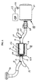
- Such a filter includes a housing 11 containing a filter body in the form of a stack of annular discs 12 having ribbed side faces defining a plurality of filtering paths leading from an outer passageway 13a defined by the outer edges of the discs radially inwardly to a central passageway 13b defined by the inner edges of the discs.
- the inner passageway is connected to an outlet 14 for the filtered air introduced via an inlet 15.
- the stack of discs 12 further includes an end disc 12a at the inlet end of the stack closing the inner passageway 13b, and urged against the other discs by a spring 12b. Further details of the construction and operation of such a disc filter appear in the above-cited patents.
- the inlet 15 is in the form of a duct having one branch 16 leading to a cyclone or other type of pre-filter 17, for directing the fluid to be filtered through the filter during a filtering operation, and a second branch 18 leading to the atmosphere for discharging cleaning air during a back-blow flushing operation, as will be described more particularly below.
- Inlet 15 further includes a valve 19 for selectively connecting branch 16 to inlet 15 during a filtering operation, or branch 18 to inlet 15 for a back-blow flushing operation.
- the filter outlet 14 is connected to a compressible fluid pulse generator, generally designated 20, for generating and applying a high-pressure pulse to the filter outlet 14 for back flushing the filter body 12 within the filter.
- the compressible fluid pulse generator 20 includes a pressure tank 21 into which pressurized air is inletted under the control of a valve 22 from a line 23 leading to a compressor CP.
- the generated high air pressure pulse is generated by sudden actuation of a valve 24, and is applied to one branch 25 of the fluid outlet 14 from the filter 10.
- the outlet 14 includes a second branch 26 leading to the utilization device to which the filtered fluid is delivered.
- Outlet 14 further includes a valve 27 for selectively connecting outlet 14 either to branch 25 or branch 26.
- Valve 24 may be controlled by a solenoid or the like (not shown) or manually.
- the filter 10 may be an air filter for removing dirt particles from the air before it is delivered to a vehicle engine via branch 26.
- the compressible fluid pulse generator 20 would generate a high-pressure pulse of air to be applied to the filter outlet 14 for back-flushing the filter discs 12 through the filter inlet 15 and the flushing fluid outlet 18.
- the litter body 12 could also be a fiber filter. In this case the air impulse would be restricted not to damage the fiber material.
- valve 24 is closed, valve 19 opens branch 16 of the inlet 15, and valve 27 opens branch 26 of the outlet 14, such that the filter 10 filters the air from the prefilter 17 and supplies the filtered air via branch 26 to the engine (or other utilization device); whereas during a back- blow flushing operation, valve 27 opens branch 25 of the filter outlet 14, valve 19 opens branch 18 of the filter inlet 15, and then valve 24 is opened, such that a high-pressure air impulse generated by generator 20 is applied to the outlet 14 of filter 10 to back-flush the filter discs 12 and to discharge the flushing air with the dirt through branch 18 of the inlet 15.
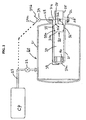
- pressure tank 21 includes the valve (corresponding to valve 24) within it, and is pressurized by a compressible fluid inletted from the compressor CP under the control of valve 22 in the inlet line 23.
- tank 21 may be pressurized with compressed air to a pressure of 5 to 10 bars.
- the outlet 28 of pressure tank 21 is controlled by an internal valve member rather than by external valve member 24.
- the internal valve member is in the form of a piston 30 movable within a cylinder 31 secured within the pressure tank 20 by fasteners 32 passing through the flanges of the tank 21, the cylinder 31, and the flange 25' of tube 25.
- Cylinder 31 is closed at one end 31a and is opened at its opposite end 31b received within the tank outlet 28.
- the inner diameter of the open end 3 1 b of the cylinder 31 is reduced, to define an inner annular shoulder 33.
- Piston 30 thus includes a large diameter section 30a on one side of its outer annular shoulder 34, and a smaller diameter section 30b on the opposite side of the shoulder.
- a sealing ring 35a is received within an annular recess formed in the large-diameter section 30a of the piston, and a second sealing ring 35b is received within an annular recess formed in the smaller-diameter section 30b of the piston.
- Cylinder 31 is in turn formed with an annular array of holes 36 through its open end, just rearwardly of its inner annular shoulder 33.
- the annular array of holes 36 thus define a large passageway for outletting the compressed air within tank 21 through the tank outlet 28 when the piston 30 is in its open position with respect to the open end of the cylinder 31.
- Fig. 2 illustrates the piston in its closed position, closing the open end of the cylinder, wherein it will be seen that sealing ring 35a is located on one side of the holes 36 to engage the inner surface of the cylinder, whereas sealing ring 35b is located on the opposite side of the hose 36 to engage the reduced-diameter section 31b of the cylinder.
- Piston 30 is normally urged to its closed position illustrated in Fig. 2 by compressed air within the compartment 37 defined by the piston 30 and the closed end 31a of the cylinder.
- the pressure within compartment 37 is controlled by an air line 38 leading from the compartment to a pilot valve 39 selectively movable to connect compartment 37 either to the compressed air source via branch 39a, or to vent the compartment 37 to the atmosphere via branch 39b.
- pilot valve 39 connects branch 39a to the compressed air source, a pressure is applied to compartment 37.
- Such a pressure would be sufficient to move piston 30 to its closed position illustrated in Fig. 2 since the surface area acting on the piston, as defined by the larger-diameter sealing ring 35a, is larger than the surface area acting in the reverse direction of the piston as defined by the smaller-diameter sealing ring 35b.
- pilot valve 39 when pilot valve 39 is moved to vent compartment 37 to the atmosphere, via its branch 39b, the compressed air within tank 21 acts on the opposite face of the piston 30 to first move the piston towards its open position.
- seal 35b disengages from the inner surface 31b of the cylinder, the larger-diameter sealing ring 35a becomes effective to define the complete area of the piston subjected to the compressed air from tank 21, to thereby accelerate the opening movement of the piston.
- Such an arrangement thus produces a quick-action opening of the piston 30 as soon as the pressure within compartment 37 is reduced.
- Compartment 37 may include a shock-absorbing body 40 for cushioning the fast-opening of the piston 30.
- the air flow through valve 39 can be limited so as to produce an air cushion between the closed end 31a of the cylinder and the piston 30.
- piston 30 produces a high-pressure pulse or blast of air from the interior of the pressure tank 21 via openings 36 through the tank outlet 28 and branch 25 of the filter outlet 14 to back-flush the filter discs 12, and to discharge the back-flushed air and dirt through branch 18 of the filter inlet 15.
- the fast-opening movement of piston 30 described above produces a sharp front to the so-produced high-pressure high-flow impulse, or blast, of air which travels through the complete length of the inner passageway 13b of the filter 10 at a very high speed, close to the speed of sound, taking approximately 1 ms for traversing the complete length of the passage 13.
- the complete passage 13 is pressurized virtually simultaneously, and therefore all the discs 12 are loaded by the same pressure wave virtually simultaneously to back-flush simultaneously the complete filter body 12.
- the pressure wave is reflected by the end plate 12a back towards the filter outlet 14, thereby sustaining, and even reinforcing, the pressure wave.
- the duration of the so-applied pressure wave can be controlled by the volume of the tank 20 and by the air pressure inside it. It will thus be seen that the described arrangement effectively back-flushes all the filtering passages virtually simultaneously with the high-pressure air blast, and thereby more effectively cleans the filtering passageways than would be the case where there is a gradual build-up in the pressure of the air pulse supplied to the filtering passageways. Thus, where there is a more gradual build-up of the pressure wave, some of the filtering passageways would be cleaned before others, thereby decreasing the resistance to the air flow through the cleaned passageways thereby decreasing the air flow through, or even bypassing the passageways still containing dirt particles.
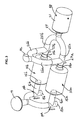
- Fig. 3 illustrates a system including two filters, therein designated 10a, 10b, both supplying filtered air to a utilization device, such as an engine, via a common filter outlet duct 42.
- the illustrated arrangement includes a common compressible fluid pulse generator 20, as described above with respect to Figs. 1 and 2, for selectively supplying, by actuating valve 24 (or internal valve 30, Fig. 2), the high-pressure air pulses via their respective outlet ducts 25a, 25b, filter outlets 14a, 14b, and flushing fluid outlets 18a, 18b.
- both of the filter inlets 16a, 16b may be supplied from the common pre-filter unit 17 by controlling their respective inlet valve 19a, 19b and outlet valves 27a, 27b, to deliver filtered air via their filtered air outlets 26a, 26b to the common outlet duct 42.
Landscapes
- Chemical & Material Sciences (AREA)
- Chemical Kinetics & Catalysis (AREA)
- Physics & Mathematics (AREA)
- Geometry (AREA)
- Filtering Of Dispersed Particles In Gases (AREA)
Description
Claims (16)
- A filter-cleaning device for cleaning a filter (10) having a filter body (12), a filter inlet (15) for fluid to be filtered, and a filter outlet (14) for the filtered fluid, said filter-cleaning device comprising:characterized in that:a compressible fluid pulse generator (20) including a pressure tank (21), a tank inlet (23) for inletting a compressible fluid, a tank outlet (25) for outletting the compressed fluid, and a valve member (24) normally in a closed position closing said tank outlet, but being actuatable to quickly move to an open position to produce a high-pressure compressible fluid pulse at said tank outlet;said tank outlet (25) being designed so as to be connectable to said filter outlet (14) such that actuating said valve member applies a high-pressure high-flow impulse of the compressible fluid pulse that propagates into said filter outlet to back-flush simultaneously the complete filter body by the high-pressure high-flow compressible fluid impulse;said valve member being in the form of a piston (30) movable within a cylinder (31) in said tank (21);said cylinder (31) having a closed end (31a), and an open end (31b) aligned with said tank outlet (25);said piston (30) being normally urged to its closed position to close said tank outlet by the compressible fluid pressure within the cylinder between its closed end and the piston, and being actuatable in a fast-action manner to quickly move to its open position by the release of said pressure between the piston and the closed end of the cylinder;said cylinder (31) is formed with a large passageway therethrough (36) adjacent its open end for directing the pressurized fluid within the tank to the tank outlet in the open position of the valve member and thereby for producing the high-pressure high-flow impulse of compressible fluid at the tank outlet;the inner diameter of the cylinder is reduced at the open end thereof (31b) aligned with said tank outlet to define an inner annular shoulder (33) in the cylinder;the outer diameter of the piston is correspondingly reduced at the end thereof facing the tank outlet to define: an outer annular shoulder (34) engageable with the inner annular shoulder of the cylinder in the closed position of the piston, a large diameter section on the side of said shoulder facing the closed end of the cylinder, and a smaller diameter section on the side of said shoulder facing the open end of the cylinder; andsaid piston (30) includes a first sealing ring (35a) on said large diameter section, and a second sealing ring (35b) on said smaller diameter section, said sealing rings being located such that in the closed position of the piston, they are on opposite sides of said large passageway (36) adjacent the open end of the cylinder.
- The device according to Claim 1, wherein said large passageway (36) adjacent the open end of the cylinder is constituted of an annular array of holes formed through the cylinder adjacent its open end.
- The device according to Claim 1, wherein said piston (30) is actuatable from its closed position to its open position by a pilot valve (39) which releases the fluid pressure between the piston and the closed end of the cylinder.
- The device according to Claim 1, wherein the closed end of the cylinder includes a shock absorbing body (40) engageable by the piston when actuated to its open position.
- The device according to Claim 1, wherein said compressible fluid pulse generator generates air pulses.
- The combination of a device according to Claim 1, and a filter (10) including a filter body (12), a filter inlet (15) for the fluid to be filtered, and a filter outlet (14) for the filtered fluid, said filter outlet being connected to said tank outlet (25) of the fluid pulse generator (20).
- The combination according to Claim 6, wherein said filter body (12) includes a stack of annular discs having outer edges defining an outer passageway (13a) through the filter, inner edges defining a central passageway (13b) through the filter, and side faces formed with ribs defining filtering paths between the two passageways.
- The combination according to Claim 7, wherein said filter inlet (15) faces the outer edges of said annular discs, and said filter outlet faces the inner edges of said discs; said filter further including an end disc (12a) at the inlet end of said stack of discs, which end disc is effective to receive said high-pressure fluid pulse applied through said central passageway via the filter outlet, and to reflect it back to the filter outlet.
- The combination according to Claim 6, wherein said filter outlet (14) includes a duct having a first branch (26) for delivering the filter fluid to a utilization device, a second branch ((25) connected to said tank outlet of the fluid pulse generator, and a valve (27) for selectively connecting said duct to said first branch or to said second branch.
- The combination according to Claim 9, wherein said filter inlet (15) includes a duct having a first branch (16) for receiving the fluid to be filtered, a second branch (18) for discharging the flushing fluid, and a valve (19) for selectively connecting said latter duct to said first branch or to said second branch.
- The combination according to Claim 10, wherein there are two filters (10a, 10b, Fig. 3) supplying the filtered fluid to a utilization device, said filters being selectively connectable to a common compressible fluid pulse generator (20) such that each filter may be selectively controlled to perform a filtering operation while the other filter is subjected to a back-flushing operation.
- A compressible fluid pulse generator comprising:characterized in that:a pressure tank (21) having a tank inlet (23) for inletting a pressurized fluid, a tank outlet (25) for outletting the pressurized fluid, and a valve member (30, 31) normally in a closed position closing said tank outlet, but actuatable to quickly move to an open position to produce a high-pressure high-flow impulse of compressible fluid at said tank outlet;said valve member being in the form of a piston (30) movable within a cylinder (31) in said tank;said cylinder (31) having a closed end (31a), and an open end (31b) aligned with said tank outlet (25);said piston (30) being normally urged to its closed position to close said tank outlet by the fluid pressure within the cylinder between its closed end and the piston, and being actuatable in a fast-action manner to quickly move to its open position by the release of said pressure between the piston and the closed end of the cylinder;said cylinder (31) is formed with a large passageway (36) therethrough adjacent its open end for directing the pressurized fluid within the tank (21) to the tank outlet (25) in the open position of the valve member (30) and thereby for producing the high-pressure high-flow impulse of compressible fluid at the tank outlet;the inner diameter of the cylinder is reduced at the open end (31b) thereof aligned with said tank outlet to define an inner annular shoulder (33) in the cylinder;the outer diameter of the piston is correspondingly reduced at the end thereof facing the tank outlet to define: an outer annular shoulder (34) engageable with the inner annular shoulder of the cylinder in the closed position of the piston, a large diameter section on the side of said shoulder facing the closed end of the cylinder, and a smaller diameter section on the side of said shoulder facing the open end of the cylinder;and said piston (30) includes a first sealing ring (35a) on said large diameter section, and a second sealing ring (35b) on said smaller diameter section, said sealing rings being located such that in the closed position of the piston, they are on opposite sides of said large passageway (36) adjacent the open end of the cylinder.
- The fluid pulse generator according to Claim 12, wherein said large passageway (36) adjacent the open end of the cylinder is constituted of an annular array of holes formed through the cylinder adjacent its open end.
- The fluid pulse generator according to Claim 12, wherein said piston (30) is actuatable from its closed position to its open position by a pilot valve (39) which releases the fluid pressure between the piston and the closed end of the cylinder.
- The fluid pulse generator according to Claim 12, wherein the closed end of the cylinder includes a shock absorbing body (40) engageable by the piston (30) when actuated to its open position.
- A method of cleaning a filter (10) having a filter body (12), a filter inlet (15) for the fluid to be filtered, and a fluid outlet (14) for the filtered fluid, said method comprising:connecting the output (25) of a fluid pulse generator (20) according to Claim 12 to the filter outlet (14);and actuating a valve member (24) of the fluid pulse generator (20) to its open position to apply a high-pressure high-flow impulse of compressible fluid to said filter outlet (14) for back-flushing said filter body (12) through the filter inlet (15).
Applications Claiming Priority (3)
| Application Number | Priority Date | Filing Date | Title |
|---|---|---|---|
| US18223100P | 2000-02-14 | 2000-02-14 | |
| PCT/IL2001/000110 WO2001058564A1 (en) | 2000-02-14 | 2001-02-04 | Filter-cleaning device and method, and fluid pulse generator particularly useful therein |
| US182231P | 2009-05-29 |
Publications (3)
| Publication Number | Publication Date |
|---|---|
| EP1200172A1 EP1200172A1 (en) | 2002-05-02 |
| EP1200172A4 EP1200172A4 (en) | 2002-05-22 |
| EP1200172B1 true EP1200172B1 (en) | 2005-04-06 |
Family
ID=22667582
Family Applications (1)
| Application Number | Title | Priority Date | Filing Date |
|---|---|---|---|
| EP01902626A Expired - Lifetime EP1200172B1 (en) | 2000-02-14 | 2001-02-04 | Filter-cleaning device and method, and fluid pulse generator particularly useful therein |
Country Status (5)
| Country | Link |
|---|---|
| US (1) | US6641646B2 (en) |
| EP (1) | EP1200172B1 (en) |
| AU (1) | AU3048301A (en) |
| DE (1) | DE60109871T2 (en) |
| WO (1) | WO2001058564A1 (en) |
Families Citing this family (38)
| Publication number | Priority date | Publication date | Assignee | Title |
|---|---|---|---|---|
| DE10151864B4 (en) * | 2001-10-24 | 2006-01-26 | Boll & Kirch Filterbau Gmbh | Method for operating a filter for liquids and system for carrying out the method |
| ITMI20012237A1 (en) * | 2001-10-25 | 2003-04-25 | Aurelio Messina | WASHING PROCEDURE AND DEVICE FOR DUST DUST FILTERS |
| WO2004071613A2 (en) * | 2003-02-12 | 2004-08-26 | Innovative Defense Technologies Ltd. | Method and construction of filters and pre-filters for extending the life cycle of the filter bodies therein |
| US20050011357A1 (en) * | 2003-07-14 | 2005-01-20 | Crawley Wilbur H. | Method and system for flushing ash from a diesel particulate filter |
| US7462222B2 (en) * | 2004-10-05 | 2008-12-09 | Caterpillar Inc. | Filter service system |
| US7384455B2 (en) * | 2004-10-05 | 2008-06-10 | Caterpillar Inc. | Filter service system and method |
| US7419532B2 (en) | 2004-10-05 | 2008-09-02 | Caterpillar Inc. | Deposition system and method |
| US7410529B2 (en) * | 2004-10-05 | 2008-08-12 | Caterpillar Inc. | Filter service system and method |
| US20060070360A1 (en) * | 2004-10-05 | 2006-04-06 | Caterpillar Inc. | Filter service system and method |
| US20060191412A1 (en) * | 2005-02-28 | 2006-08-31 | Caterpillar Inc. | Filter service system and method |
| US7410521B2 (en) * | 2005-02-28 | 2008-08-12 | Caterpillar Inc. | Filter service system and method |
| US7410530B2 (en) * | 2005-03-04 | 2008-08-12 | Donaldson Company, Inc. | Apparatus for cleaning exhaust aftertreatment devices and methods |
| US7468085B2 (en) * | 2005-12-19 | 2008-12-23 | Caterpillar Inc. | System and method for cleaning a filter |
| US7357829B2 (en) * | 2006-01-10 | 2008-04-15 | International Truck Intellectual Property Company, Llc | Diesel particulate filter cleaning device and method |
| US20070289917A1 (en) * | 2006-06-15 | 2007-12-20 | Mylin John M | Separation system and method of operating |
| US8117832B2 (en) | 2006-06-19 | 2012-02-21 | Donaldson Company, Inc. | Exhaust treatment device with electric regeneration system |
| US8256060B2 (en) * | 2007-01-30 | 2012-09-04 | Donaldson Company, Inc. | Apparatus for cleaning exhaust aftertreatment devices and methods |
| US8142552B2 (en) * | 2007-06-29 | 2012-03-27 | Caterpillar Inc. | Filter purge system utilizing a reactive propellant |
| US8157897B2 (en) * | 2007-06-29 | 2012-04-17 | Caterpillar Inc. | Filter purge system utilizing impact wave generating device and vacuum source |
| US20100037423A1 (en) * | 2008-07-10 | 2010-02-18 | Herman John T | Apparatus for Cleaning Exhaust Aftertreatment Devices and Methods |
| ITMI20081411A1 (en) * | 2008-07-30 | 2010-01-31 | C M V Di Villa Alberto Maria | DEVICE FOR CLEANING A FILTERING CARTRIDGE IN ASPIRATORS AND SIMILARS. |
| US8057608B1 (en) | 2008-09-26 | 2011-11-15 | Research International, Inc | Extraction device and methods |
| US8844270B2 (en) * | 2009-01-16 | 2014-09-30 | Donaldson Company, Inc. | Diesel particulate filter regeneration system including shore station |
| US8241403B2 (en) * | 2009-06-08 | 2012-08-14 | Catalytic Solutions, Inc. | Apparatus and method for regenerating a carbon filter |
| JP5665297B2 (en) | 2009-09-30 | 2015-02-04 | 三菱重工業株式会社 | Dust removal device |
| US8393050B2 (en) * | 2009-10-28 | 2013-03-12 | Robert M. Witter | Portable cyclonic dust collector/vacuum cleaner |
| US8375713B2 (en) * | 2009-12-04 | 2013-02-19 | International Engine Intellectual Property Company, Llc | EGR cooler cleaning system and method |
| CN101816847B (en) * | 2010-05-05 | 2012-02-29 | 北京天地玛珂电液控制系统有限公司 | backwash filter |
| US20130232931A1 (en) * | 2012-03-09 | 2013-09-12 | Stewart Miller Malcolm | Inline duct filter |
| DE102012009848A1 (en) | 2012-05-21 | 2013-11-21 | Anton Blank | Depth-precise capillary needle for repeated introduction of liquid substances into the skin. |
| DE102012009991A1 (en) | 2012-05-22 | 2013-11-28 | Anton Blank | Needle module with automatic frequency and amplitude adjustment |
| US9010098B2 (en) * | 2012-10-24 | 2015-04-21 | Electro-Motive Diesel, Inc. | After-treatment device |
| IL227785A (en) | 2013-08-04 | 2016-09-29 | Tavlit Plastics Ltd | Self-cleaning filter apparatus |
| US10359010B2 (en) * | 2014-02-16 | 2019-07-23 | K&N Engineering, Inc. | Air box with integrated filter media |
| CN108619781A (en) * | 2017-03-21 | 2018-10-09 | 芜湖美的厨卫电器制造有限公司 | Purifier and its filter core flush control method |
| CN109939524B (en) * | 2019-03-28 | 2021-07-09 | 赵澄 | A dust collecting equipment for factory building |
| EP3888516A1 (en) * | 2020-04-01 | 2021-10-06 | Hilti Aktiengesellschaft | Filter cleaning according to requirements |
| CN113457284B (en) * | 2021-07-27 | 2024-05-14 | 中国北方车辆研究所 | Automatic filter element cleaning and maintaining device |
Family Cites Families (12)
| Publication number | Priority date | Publication date | Assignee | Title |
|---|---|---|---|---|
| US2679320A (en) * | 1951-12-01 | 1954-05-25 | Air Maze Corp | Dual filter with pressure differential selector valve |
| US3394735A (en) * | 1967-02-27 | 1968-07-30 | Andale Co | Valve member for a duplex strainer |
| FI56773C (en) * | 1973-02-26 | 1980-04-10 | Inoma Filter Ab | SAETT FOER RENING AV STOFTFILTER |
| SE391458B (en) * | 1974-05-02 | 1977-02-21 | Svenska Flaektfabriken Ab | KIT AND DEVICE FOR CLEANING HOSE FILTER WITH PRESSURE PULSE OF CLEANING MEDIUM |
| DE2424180C3 (en) * | 1974-05-17 | 1983-01-05 | Klöckner-Humboldt-Deutz AG, 5000 Köln | Filter system for internal combustion engines |
| DE7831128U1 (en) * | 1978-10-19 | 1979-02-15 | Boll & Kirch Filterbau Gmbh, 5000 Koeln | BACK FLUSH FILTER |
| US4624689A (en) * | 1982-02-04 | 1986-11-25 | Mike Volk Co., Inc. | Pneumatic shock wave generator for cleaning filter cartridges |
| DE3832679A1 (en) | 1988-09-27 | 1990-03-29 | Boll & Kirch Filter | BACKPACK FILTER |
| SE466362B (en) | 1990-06-21 | 1992-02-03 | Flaekt Ab | VALVE DEVICE, SPEC FOR PRESSURE AIR PULSES WITH VARIOUS OPERATING DATA |
| GB2272847B (en) | 1992-11-27 | 1996-06-12 | Europ Gas Turbines Ltd | A reverse flush gas valve |
| IL111901A (en) * | 1994-12-06 | 1999-08-17 | Gideon Rosenberg Dba Itec Init | Air filter and method of operating same |
| US5837017A (en) * | 1996-05-02 | 1998-11-17 | Bha Group Holdings, Inc. | Apparatus for cleaning baghouse filters |
-
2001
- 2001-02-04 WO PCT/IL2001/000110 patent/WO2001058564A1/en not_active Ceased
- 2001-02-04 EP EP01902626A patent/EP1200172B1/en not_active Expired - Lifetime
- 2001-02-04 US US09/958,317 patent/US6641646B2/en not_active Expired - Fee Related
- 2001-02-04 AU AU30483/01A patent/AU3048301A/en not_active Abandoned
- 2001-02-04 DE DE60109871T patent/DE60109871T2/en not_active Expired - Lifetime
Also Published As
| Publication number | Publication date |
|---|---|
| US6641646B2 (en) | 2003-11-04 |
| WO2001058564A1 (en) | 2001-08-16 |
| DE60109871D1 (en) | 2005-05-12 |
| DE60109871T2 (en) | 2006-04-27 |
| EP1200172A1 (en) | 2002-05-02 |
| AU3048301A (en) | 2001-08-20 |
| US20020157539A1 (en) | 2002-10-31 |
| EP1200172A4 (en) | 2002-05-22 |
Similar Documents
| Publication | Publication Date | Title |
|---|---|---|
| US6641646B2 (en) | Filter-cleaning device and method, and fluid pulse generator particularly useful therein | |
| US7462222B2 (en) | Filter service system | |
| CN1960809B (en) | A powder coating system | |
| US3487609A (en) | Method and apparatus for filtering a gaseous medium | |
| US6576045B2 (en) | Multi-stage diesel particulate collector system with combined processes of inertial impaction, virtual impaction, and filtration | |
| CN104918673A (en) | Cleanable filter | |
| US6736881B2 (en) | Method and arrangement for cleaning pipe-shaped filter elements | |
| CA1052294A (en) | Dust filter unit and a method of cleaning a dust filter unit | |
| TWI762657B (en) | Silencer and ejector in which silencer is used | |
| JP5886964B2 (en) | Filter device | |
| MX2007000041A (en) | Diesel particulate filter cleaning device and method. | |
| JP2017154133A (en) | Split flow pulse jet cleaning device and system | |
| US8021467B2 (en) | Cleaning process for cleaning filtration material of a gas filter and a device for carrying out the process | |
| JP2012228691A (en) | Filter structure for cleaning process gas loaded with particle and method for cleaning filter unit of the filter structure | |
| JP2016065640A (en) | Valve with small container approaching diameter | |
| US20060070360A1 (en) | Filter service system and method | |
| JPH05245319A (en) | Method and device for preventing dust release in bag filter | |
| JPH1066816A (en) | Apparatus and method for removing dust | |
| SE502345C2 (en) | Vacuum unit and vacuum toilet system comprising such unit | |
| US6663693B2 (en) | Duct cleaning for powder spray system | |
| JP3117274B2 (en) | Dust collection device | |
| RU2008071C1 (en) | Hose filter | |
| US20250083082A1 (en) | Airbox with debris removal system | |
| JPS6018448B2 (en) | Buzz filter | |
| SU1736571A1 (en) | Hose filter |
Legal Events
| Date | Code | Title | Description |
|---|---|---|---|
| PUAI | Public reference made under article 153(3) epc to a published international application that has entered the european phase |
Free format text: ORIGINAL CODE: 0009012 |
|
| 17P | Request for examination filed |
Effective date: 20020117 |
|
| AK | Designated contracting states |
Kind code of ref document: A1 Designated state(s): AT BE CH CY DE DK ES FI FR GB GR IE IT LI LU MC NL PT SE TR |
|
| AX | Request for extension of the european patent |
Free format text: AL;LT;LV;MK;RO;SI |
|
| A4 | Supplementary search report drawn up and despatched |
Effective date: 20020405 |
|
| RIC1 | Information provided on ipc code assigned before grant |
Free format text: 7B 01D 29/52 A, 7B 01D 29/66 B, 7B 01D 46/24 B |
|
| 17Q | First examination report despatched |
Effective date: 20030502 |
|
| RBV | Designated contracting states (corrected) |
Designated state(s): DE ES FR IT |
|
| GRAP | Despatch of communication of intention to grant a patent |
Free format text: ORIGINAL CODE: EPIDOSNIGR1 |
|
| GRAS | Grant fee paid |
Free format text: ORIGINAL CODE: EPIDOSNIGR3 |
|
| GRAA | (expected) grant |
Free format text: ORIGINAL CODE: 0009210 |
|
| AK | Designated contracting states |
Kind code of ref document: B1 Designated state(s): DE ES FR IT |
|
| REG | Reference to a national code |
Ref country code: IE Ref legal event code: FG4D |
|
| REF | Corresponds to: |
Ref document number: 60109871 Country of ref document: DE Date of ref document: 20050512 Kind code of ref document: P |
|
| PG25 | Lapsed in a contracting state [announced via postgrant information from national office to epo] |
Ref country code: ES Free format text: LAPSE BECAUSE OF FAILURE TO SUBMIT A TRANSLATION OF THE DESCRIPTION OR TO PAY THE FEE WITHIN THE PRESCRIBED TIME-LIMIT Effective date: 20050717 |
|
| PLBE | No opposition filed within time limit |
Free format text: ORIGINAL CODE: 0009261 |
|
| STAA | Information on the status of an ep patent application or granted ep patent |
Free format text: STATUS: NO OPPOSITION FILED WITHIN TIME LIMIT |
|
| ET | Fr: translation filed | ||
| 26N | No opposition filed |
Effective date: 20060110 |
|
| PGFP | Annual fee paid to national office [announced via postgrant information from national office to epo] |
Ref country code: IT Payment date: 20100223 Year of fee payment: 10 Ref country code: FR Payment date: 20100226 Year of fee payment: 10 |
|
| PGFP | Annual fee paid to national office [announced via postgrant information from national office to epo] |
Ref country code: DE Payment date: 20100219 Year of fee payment: 10 |
|
| REG | Reference to a national code |
Ref country code: FR Ref legal event code: ST Effective date: 20111102 |
|
| PG25 | Lapsed in a contracting state [announced via postgrant information from national office to epo] |
Ref country code: IT Free format text: LAPSE BECAUSE OF NON-PAYMENT OF DUE FEES Effective date: 20110204 |
|
| REG | Reference to a national code |
Ref country code: DE Ref legal event code: R119 Ref document number: 60109871 Country of ref document: DE Effective date: 20110901 |
|
| PG25 | Lapsed in a contracting state [announced via postgrant information from national office to epo] |
Ref country code: FR Free format text: LAPSE BECAUSE OF NON-PAYMENT OF DUE FEES Effective date: 20110228 |
|
| PG25 | Lapsed in a contracting state [announced via postgrant information from national office to epo] |
Ref country code: DE Free format text: LAPSE BECAUSE OF NON-PAYMENT OF DUE FEES Effective date: 20110901 |