EP1200164B1 - Doll having realistic twisting midriff - Google Patents
Doll having realistic twisting midriff Download PDFInfo
- Publication number
- EP1200164B1 EP1200164B1 EP00936069A EP00936069A EP1200164B1 EP 1200164 B1 EP1200164 B1 EP 1200164B1 EP 00936069 A EP00936069 A EP 00936069A EP 00936069 A EP00936069 A EP 00936069A EP 1200164 B1 EP1200164 B1 EP 1200164B1
- Authority
- EP
- European Patent Office
- Prior art keywords
- doll
- ball
- armature
- socket
- midriff
- Prior art date
- Legal status (The legal status is an assumption and is not a legal conclusion. Google has not performed a legal analysis and makes no representation as to the accuracy of the status listed.)
- Expired - Lifetime
Links
- 238000005304 joining Methods 0.000 claims description 2
- 238000004519 manufacturing process Methods 0.000 description 9
- 210000001624 hip Anatomy 0.000 description 8
- 239000000463 material Substances 0.000 description 8
- 239000000853 adhesive Substances 0.000 description 6
- 230000001070 adhesive effect Effects 0.000 description 6
- 238000010276 construction Methods 0.000 description 4
- 238000000034 method Methods 0.000 description 4
- 239000002991 molded plastic Substances 0.000 description 4
- 230000009471 action Effects 0.000 description 2
- 230000008878 coupling Effects 0.000 description 2
- 238000010168 coupling process Methods 0.000 description 2
- 238000005859 coupling reaction Methods 0.000 description 2
- 238000003780 insertion Methods 0.000 description 2
- 230000037431 insertion Effects 0.000 description 2
- 238000012986 modification Methods 0.000 description 2
- 230000004048 modification Effects 0.000 description 2
- 238000003466 welding Methods 0.000 description 2
- 241000086550 Dinosauria Species 0.000 description 1
- 241000238631 Hexapoda Species 0.000 description 1
- 241001465754 Metazoa Species 0.000 description 1
- 230000001154 acute effect Effects 0.000 description 1
- 230000006978 adaptation Effects 0.000 description 1
- 238000005452 bending Methods 0.000 description 1
- 230000008859 change Effects 0.000 description 1
- 230000002079 cooperative effect Effects 0.000 description 1
- 239000000835 fiber Substances 0.000 description 1
- 239000002657 fibrous material Substances 0.000 description 1
- 239000000945 filler Substances 0.000 description 1
- 239000012858 resilient material Substances 0.000 description 1
- 239000007779 soft material Substances 0.000 description 1
Images


Classifications
-
- A—HUMAN NECESSITIES
- A63—SPORTS; GAMES; AMUSEMENTS
- A63H—TOYS, e.g. TOPS, DOLLS, HOOPS OR BUILDING BLOCKS
- A63H3/00—Dolls
- A63H3/36—Details; Accessories
- A63H3/46—Connections for limbs
Definitions
- This invention relates generally to fashion dolls and particularly to those fabricated to have movable and articulated body parts.
- Fashion dolls are a well known and a very popular type of doll toy product. While the fabrication of fashion dolls has varied some what through the years, generally all are fabricated of relatively rigid molded plastic components which include a torso or main body having a neck supporting a head together with articulated arms and legs all of which usually formed of a relatively rigid molded plastic. In most fashion dolls, arms and legs move to facilitate dressing the doll in various interchangeable clothing garments. In addition, most fashion dolls are sufficiently articulated to be capable of being posed in various positions such as sitting, standing or lying prone. A variety of cooperating accessories are also used with fashion dolls which have included such devices as cars, houses, work areas such as offices and campers or the like.
- fashion dolls One of the more interesting aspects of fashion dolls is the play pattern which utilizes a variety of stylish and often very fashionable garments which the dolls may wear. Much of the appeal of fashion dolls involves the use of such garments. Notsurprisingly, practitioners in the toy arts providing fashion dolls often strive to make available garments which are in tune with the latest styles and fashions or which fit a particular selected theme. One style or fashion which periodically rises in the fashion world involves a bare midriff look or style.
- US Patent 4,968,282 issued to Robson et al. sets forth a POSEABLE DOLL constructed of sub units connected to one another by ball and socket joints. A skin which encloses the sub units is secured to the sub units by insertion of appendages into sockets in the sub units and by means of a fastener which snaps into a groove pining the skin to the doll.
- US Patent 3,699,710 issued to Glass et al. sets forth a DOLL JOINT having a doll body defining upper and lower torso components movably related to each other and characterized by the connection of the torso components so as to permit rotational movement therebetween.
- US Patent 3,425,155 issued to Ryan et al. sets forth a DOLL CONSTRUCTION FOR NATURAL MOVEMENTS AND POSITIONS having an upper and lower torso joined by a rotational attachment.
- the upper and lower torso portions of the doll as well as the head to neck attachment of the doll is rotatable with respect to a plane of rotation which is angled by an acute angle relative to the height of the doll body.
- US Patent 4,135,327 issued to Sapkus et al. sets forth a DOLL CONSTRUCTION WITH PIVOTABLE TORSO MEMBERS having upper and lower hollow torso members supportable in an upright position along the longitudinal center line of the doll.
- the doll torso portions are adapted to be pivoted with respect to each other about an axis angled at approximately thirty degrees from the longitudinal axis of the doll.
- US Patent 4,662,857 issued to Quinn et al. sets forth an ARTICULATED SOFT DOLL CONSTRUCTION ASSEMBLY in which a soft skin covers a soft head and a soft torso of a doll.
- the torso has a first skin covering a fiber filler material formed with an opening in which a neck connecting member is received.
- a second soft skin cover is used to cover a soft head filled with a fiber material.
- a neck plug is received through an opening in the head and the second soft skin cover.
- US Patent 5,752,869 issued to Huff sets forth a TOY CONSTRUCTION SET suitable for modeling an animal, bird, insect, dinosaur humanoid figure.
- a skeleton having a plurality of snap-fitted ball and socket members which may be interchanged facilitates the adaptation to various types of figures.
- German patent DE 928 751 discloses a device for changing the body height of a doll as well as for flexing the upper part of the doll in all directions.
- An elastic ring made of a flexible material is placed in the hip region between the end plates of the upper and lower parts of the body.
- Figure 1 sets forth a front perspective view of a doll constructed in accordance with the present invention and generally referenced by numeral 10.
- Doll 10 includes a doll body 11 having an upper portion 12, a midriff 20, and a lower body 17.
- Upper body 12 is formed of a front portion 23 and a rear portion 24 and supports a pair of arms 15 and 16 in the manner set forth below in greater detail.
- lower body 17 is formed of a front portion 21 and a rear portion 22 and supports a pair of legs 18 and 19 in the manner set forth below in greater detail.
- Midriff 20 is joined to upper body 12 along a seam 26 and is joined to lower body 17 along a seam 25.
- Upper body 12 further defines an upwardly extending neck 13 having a head connector 46.
- the lower portion of a typical doll head 14 is shown in dash-line representation. It will be understood that head 14 is connectable to head connector 46 in accordance with conventional fabrication techniques (not shown).
- upper body 12 and arms 15 and 16 are preferably fabricated of a relatively rigid molded plastic material or the like. Front portion 23 and rear portion 22 are joined utilizing conventional fabrication techniques such as sonic welding, thermal welding or adhesive attachment or other equivalent attachments.
- lower body 17 together with legs 18 and 19 are also preferably fabricated of a relatively rigid material such as molded plastic.
- midriff 20 is fabricated of a soft resilient flexible material such as rubber or the like and is supported by an upper body armature and a lower body armature joined by a ball and socket structure in the manner set forth below in greater detail.
- midriff 20 is generally contoured and textured to closely resemble human skin in both color and flexing characteristics. Accordingly, the twisting motion between upper body 12 and lower body 17 is accommodated by the flexibility of midriff 20.
- the unique structure of midriff 20 and the supporting armatures therein maintains a realistic natural midriff appearance for body 11 despite its capability to twist or flex.
- the present invention doll is uniquely configured and constructed to allow the doll to wear a variety of so-called "bare midriff" fashion garments.
- Figure 2 sets forth a front view of doll 10. showing the underlying structure and supporting armatures thereof in dash-line or invisible representation.
- doll 10 includes an upper body 12 and a lower body 17 coupled by a resilient midriff 20.
- upper body 12 supports a neck 13 having a head connector 46 supported therein.
- a pair of arms 15 and 16 having arm bearings 41 and 45 respectively and ball ends 43 and 44 are pivotally secured to upper body 12.
- Upper body 12 defines a lower edge 48 which meets midriff 20 to form a seam 26.
- lower body 17 defines an upper edge 56 which meets midriff 20 to form a seam 25.
- Lower body 17 supports a lower body armature 70 secured therein by cooperating posts 27 and 28 in the manner seen in Figure 3.
- Lower body armature 70 includes a pair of outwardly extending hip supports 76 and 77 which in turn support a pair of spring clips 80 and 84. Spring clips 80 and 84 are received within a pair of split balls 81 and 85.
- Lower body armature 70 further includes a horizontally disposed plate 71 and an upwardly extending ball support 72. A ball 73 is supported upon ball support 72.
- Doll 10 further includes a pair of leg armatures 90 and 92 upon which legs 18 and 19 are formed.
- leg armatures 90 and 92 are molded into legs 18 and 19.
- a rigid structure for legs 18 and 19 may be obtained while utilizing a some what softer more realistic material for legs 18 and 19.
- Leg armature 90 defines a hip socket 91 receiving split ball 81 and spring clip 80.
- leg armature 92 defines a hip socket 95 which receives split ball 85 and spring clip 84.
- the resulting assembly of legs 18 and 19 and lower body armature 70 provides pivotal attachment of legs 18 and 19.
- body 11 includes an upper body armature 30 having a pair of forwardly extending supports 36 and 37.
- Upper body armature 30 further includes a rearwardly extending flange 35 (seen in Figure 4) which is supported within grooves 50 and 51 or rear portion 24 (also seen in Figure 4). Suffice it to note here, that upper body armature 30 is secured within upper body 12 in a rigid attachment.
- Upper body armature 30 further includes a downwardly extending housing supporting a generally horizontal plate 34. Plate 34 in turn supports a downwardly extending socket support 33 having a socket 32 joined thereto.
- ball 73 is pivotally supported within socket 32.
- midriff 20 is molded upon upper body armature 30 after socket 32 receives ball 73.
- plates 34 and 71 are structured to grip the material of midriff 20 as midriff 20 is molded thereon.
- Figure 3 sets forth a section view of doll taken along section lines 3-3 in Figure 2.
- doll 10 includes a body 11 formed of an upper body 12 and a lower body 17 joined by a flexible midriff 20.
- upper body 12 is formed of a front portion 23 and a rear portion 24 joined by adhesive attachment.
- Upper body 12 defines a neck 13 supporting a head connector 46 which is used in accordance with conventional fabrication techniques to secure a conventional doll head (not shown).
- Front portion 23 of upper body 12 defines a lower edge 48 while rear portion 24 thereof defines a lower edge 47.
- An arm baring 41 rotatably supports arm 15 (seen in Figure 2).
- Lower body 17 is formed of a front portion 21 and a rear portion 22 joined by conventional attachment such as adhesive attachment or the like.
- Front portion 21 defines a pair of rearwardly extending bosses 100 and 101 while rear portion 22 defines a pair of forwardly extending posts 27 and 28.
- Posts 27 and 28 are received within bosses 100 and 101 and secured by conventional means such as adhesive attachment or the like.
- an upper body armature 30 includes a flange 35 received within a pair of grooves 50 and 51 (groove 50 seen in Figure 4) both of which are formed in rear portion 24.
- Upper body armature 30 further includes a downwardly extending housing 31 having a plate 34 extending therefrom.
- a socket support 33 extends downwardly beyond plate 34 and supports a socket 32.
- Socket 32 includes a pair of limit tabs 105 and 106.
- a lower body armature 70 defines a pair of apertures 78 and 79 which receive bosses 100 and 101 together with posts 27 and 28 to securely attach lower body armature 70 within lower body 17. Conventional attachment such as adhesive attachment or the like is used to secure lower body armature 70.
- Lower body armature 70 further includes an upwardly extending ball support 72 and a laterally extending plate 71. Ball support 72 is joined to a ball 73 which is received within socket 32 of upper body armature 30. Ball 73 defines a front opening 74 and a rear opening 75. As is better seen in Figure 5, front opening 74 receives limit tab 106 while rear opening 75 receives limit tab 105.
- limit tabs 105 and 106 within openings 75 and 74 is described below in connection with Figure 5 in greater detail. Suffice it to note here, that the cooperative effect thereof, provides an angular limit on the twisting or pivoting range of motion between ball 73 and socket 32. This limits the twisting of midriff 20 a realistic degree of motion to maintain realism.
- front portion 21 of lower body 17 defines an upper edge 57 while rear portion 22 thereof defines an upper edge 56.
- a lip 55 receives edges 56 and 57 to provide a smooth seam 25 between midriff 20 and lower body 17.
- a similar smooth seam 26 is formed between midriff 20 and upper body portion 12 at edges 47 and 48.
- the pivotal attachment between upper body 12 and lower body 17 provided by ball 73 of lower body armature 70 and socket 32 of upper body armature 30 together with the smooth flexible and realistically contoured molded on structure of midriff 20 combines to provide a novel doll fabrication which is suitable for wearing garments having a bare midriff or exposed midriff area.
- the degree of pivotal twisting of upper body 12 with respect to lower body 17 or vise versa is limited by the structure is limited by the structure of ball 73 and socket 32 to maintain a realistic range of motion and to avoid damage to the present invention doll.
- the attachment of ball 73 within socket 32 also provides additional strength which resists forces tending to stretch body 11 in a manner pulling upper body 12 and lower body 17 apart.
- upper body armature 30 and lower body armature 70 in resisting this force allows midriff 20 to be formed of a highly realistic feeling resilient material closely simulating the touch and feel of the human body. But for the provision of armatures 30 and 70, midriff 20 would of necessity need to be fabricated of a substantially stronger and therefore less realistic material.
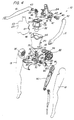
- FIG 4 sets forth a perspective assembly view of the present invention doll.
- doll 10 includes a front portion 23 and a rear portion 24 which are joined to form upper body 12 (seen in Figure 1).
- Rear portion 24 defines socket portions 60 and 62 while front portion 23 defines docket portions 61 and 63.
- rear portion 24 defines grooves 50 and 51 and bottom edge 47.
- Front portion 23 defines a bottom edge 48.
- socket portions 60 and 61 form a shoulder socket as due socket portions 62 and 63.
- a pair of arms 15 and 16 having ball ends 42 and 43 together with arm bearings 41 and 44 are received within the shoulder sockets thus formed.
- an upper body armature 30 having a housing 31 supporting a rearwardly extending flange 35 and forwardly extending supports 36 and 37 is captivated between front portion 23 and rear portion 24. This captivation results from the insertion of flange 35 within grooves 50 and 51 prior to the assembly of front portion 23 to rear portion 24.
- Upper body armature 30 further includes a plate 34 supporting a downwardly extending socket support 33 which in turn supports a downwardly open socket 32.
- Front portion 21 and rear portion 22 combine to form lower body 17 (seen in Figure 1).
- a lower body armature 70 defines apertures 78 and 79 together with outwardly extending hip supports 76 and 77. Hip supports 76 and 77 further support spring clips 80 and 81 respectively.
- a pair of split balls 81 and 85 having slots 82 and 86 together with apertures 83 and 87 formed therein are configured to receive spring clips 80 and 84.
- a pair of legs 18 and 19 having supporting armatures 90 and 92 (armature 92 seen in Figure 2) define respective hip sockets 91 and 95.
- Front portion 21 and rear portion 22 of lower body 17 are joined using conventional attachment such as adhesive attachment or the like, to captivate lower body armature 70 upon posts 27 and 28 passing through apertures 78 and 79 respectively.
- legs 18 and 19 are assembled by initially inserting split balls 81 and 85 into hip sockets 91 and 95 respectively. Thereafter, spring clips 80 and 84 are forced through apertures 83 and 87 respectively and are resiliently locked therein to secure legs 18 and 19 to lower body armature 70.
- Lower body armature 70 further includes a plate 71 having an upwardly extending ball support 72 which in turn supports a ball 73.
- Ball 73 defines a front opening 74 and a rear opening 85.
- midriff 20 is formed upon doll 10 to provide the completed doll shown in Figure 1.
- midriff 20 is formed of a flexible resilient soft material such as rubber or the like and is molded directly upon the remainder of doll 10 to form lips 46 and 55 against edges 47 and 48 of front portion 23 and rear portion 24 and against edges 56 and 57 of rear portion 22 and front portion 21.
- midriff 20 is shown pre-formed for purposes of illustration in Figure 4, it will be understood that in the preferred fabrication of the present invention shown in Figure 2, midriff 20 is molded upon upper body armature 30 and lower body armature 70.
- Figure 5 sets forth a section view of doll 10 taken along section lines 5-5 in Figure 2.
- Figure 5 is provided to more clearly shown the limitation of pivotal movement between ball 73 and socket 32 which in turn limits the twisting or pivotal motion obtainable between upper body 12 and lower body 17.
- a ball 73 defining a front opening 74 and a rear opening 75 is received within a socket 32 in accordance with the ball and socket joint formed between upper body armature 30 and lower body armature 70 shown in Figure 2.
- Socket 32 defines a limit tab 105 extending into opening 75 and a limit tab 106 extending into opening 74.
- Midriff 20 is shown molded upon socket 32 and ball 73 in the manner shown in Figure 2.
- twisting movement between upper body 12 and lower body 17 is accommodating by the flexing of midriff 20 together with the rotation of ball 73 within socket 32.
- the rotation motion of ball 73 in either direction is limited by the extension of tabs 105 and 106.
- the twisting movement or rotation of upper body 12 with respect to lower body 17 is limited to a realistic angular twist or pivoting motion.
Landscapes
- Toys (AREA)
Abstract
Description
- This invention relates generally to fashion dolls and particularly to those fabricated to have movable and articulated body parts.
- Fashion dolls are a well known and a very popular type of doll toy product. While the fabrication of fashion dolls has varied some what through the years, generally all are fabricated of relatively rigid molded plastic components which include a torso or main body having a neck supporting a head together with articulated arms and legs all of which usually formed of a relatively rigid molded plastic. In most fashion dolls, arms and legs move to facilitate dressing the doll in various interchangeable clothing garments. In addition, most fashion dolls are sufficiently articulated to be capable of being posed in various positions such as sitting, standing or lying prone. A variety of cooperating accessories are also used with fashion dolls which have included such devices as cars, houses, work areas such as offices and campers or the like.
- One of the more interesting aspects of fashion dolls is the play pattern which utilizes a variety of stylish and often very fashionable garments which the dolls may wear. Much of the appeal of fashion dolls involves the use of such garments. Notsurprisingly, practitioners in the toy arts providing fashion dolls often strive to make available garments which are in tune with the latest styles and fashions or which fit a particular selected theme. One style or fashion which periodically rises in the fashion world involves a bare midriff look or style. The utilization of such bare midriff styles present substantial difficulty for manufactures of fashion dolls in that the torso which is exposed in a typical fashion doll includes various unnatural visible joint structures or structural elements for example, US Patent 3,942,284 issued to Kublan sets forth a DOLL WITH SEVEN SPHERICAL TORSO JOINTS AND FIVE APPENDAGES HELD BY THREE-SECURED ELASTIC MEMBERS having a doll utilizing a torso formed of an upper torso and lower torso joined by a ball joint together with a pair of arms and a pair of legs pivotally joined to the upper and lower torso portions. A single elastic member extends from the lower torso through the upper torso and into the doll head while second and third elastic members are stretched between the arm pair and the leg pair.
- US Patent 4,968,282 issued to Robson et al. sets forth a POSEABLE DOLL constructed of sub units connected to one another by ball and socket joints. A skin which encloses the sub units is secured to the sub units by insertion of appendages into sockets in the sub units and by means of a fastener which snaps into a groove pining the skin to the doll.
- US Patent 3,699,710 issued to Glass et al. sets forth a DOLL JOINT having a doll body defining upper and lower torso components movably related to each other and characterized by the connection of the torso components so as to permit rotational movement therebetween.
- US Patent 3,425,155 issued to Ryan et al. sets forth a DOLL CONSTRUCTION FOR NATURAL MOVEMENTS AND POSITIONS having an upper and lower torso joined by a rotational attachment. The upper and lower torso portions of the doll as well as the head to neck attachment of the doll is rotatable with respect to a plane of rotation which is angled by an acute angle relative to the height of the doll body.
- US Patent 4,135,327 issued to Sapkus et al. sets forth a DOLL CONSTRUCTION WITH PIVOTABLE TORSO MEMBERS having upper and lower hollow torso members supportable in an upright position along the longitudinal center line of the doll. The doll torso portions are adapted to be pivoted with respect to each other about an axis angled at approximately thirty degrees from the longitudinal axis of the doll.
- US Patent 4,662,857 issued to Quinn et al. sets forth an ARTICULATED SOFT DOLL CONSTRUCTION ASSEMBLY in which a soft skin covers a soft head and a soft torso of a doll. The torso has a first skin covering a fiber filler material formed with an opening in which a neck connecting member is received. A second soft skin cover is used to cover a soft head filled with a fiber material. A neck plug is received through an opening in the head and the second soft skin cover.
- US Patent 4,723,932 issued to Kelley et al. sets forth a TOY DOLL HAVING ARTICULATED ARMS AND A TILTABLE UPPER TORSO in which upper and lower torso portions are joined at a ball and socket joint. The upper torso is coupled to the lower torso by a rotatable shaft which allows tilting thereof.
- US Patent 4,954,118 issued to Refabert sets forth FLEXIBLE BODIED DOLLS having a plurality of rigid or semi-rigid members embedded within the body. The rigid or semi-rigid members form a supporting skeleton for the doll and facilitate posing by bending the doll and its supporting members.
- US Patent 4,995,846 issued to Mariol sets forth a TOY FIGURE WITH PIVOTAL LOWER TORSO having a lower torso and legs defining an angled plane together with an upper torso, arms and head defining a correspondingly angled plane and a rotatable coupling therebetween. The angled plane about which the upper and lower portions of the toy figure are rotatable causes the angle between body portions to change as the figure is rotated.
- US Patent 3,124,901 issued to Beebe sets forth a BALL JOINT BETWEEN DOLL HEAD AND BODY which facilitates a snap-in attachment and pivotal support of a doll head upon the neck and shoulders of a doll body.
- US Patent 5,752,869 issued to Huff sets forth a TOY CONSTRUCTION SET suitable for modeling an animal, bird, insect, dinosaur humanoid figure. A skeleton having a plurality of snap-fitted ball and socket members which may be interchanged facilitates the adaptation to various types of figures.
- The German patent DE 928 751 discloses a device for changing the body height of a doll as well as for flexing the upper part of the doll in all directions. An elastic ring made of a flexible material is placed in the hip region between the end plates of the upper and lower parts of the body.
- While the foregoing described prior art devices have improved the art and is some instances enjoyed commercial success, there remains nonetheless a continuing need in the art for ever more improved, interesting and realistic fashion dolls.
- Accordingly, it is a general object of the present invention to provide an improved fashion doll. It is a more particular object of the present invention to provide an improved fashion doll which presents a realistic appearing twistable torso suitable for use with "bare midriff" fashions or the like.
- In accordance with the present invention there is provided a doll according to claim 1.
- The features of the present invention, which are believed to be novel, are set forth with particularity in the appended claims. The invention, together with further objects and advantages thereof, may best be understood by reference to the following description taken in conjunction with the accompanying drawings, in the several figures of which like reference numerals identify like elements and in which:
- Figure 1 sets forth a front perspective view of a fashion doll body constructed in accordance with the present invention;
- Figure 2 sets forth a partial front view of the present invention doll having the supporting skeletal members shown in invisible dash-line;
- Figure 3 sets forth a section view of the present invention doll taken along section lines 3-3 in Figure 2;
- Figure 4 sets forth a perspective assembly view of the present invention doll;
- Figure 5 sets forth a section view of the present invention doll taken along section lines 5-5 in Figure 2.
- Figure 1 sets forth a front perspective view of a doll constructed in accordance with the present invention and generally referenced by
numeral 10.Doll 10 includes a doll body 11 having anupper portion 12, amidriff 20, and alower body 17.Upper body 12 is formed of afront portion 23 and arear portion 24 and supports a pair ofarms lower body 17 is formed of afront portion 21 and arear portion 22 and supports a pair oflegs upper body 12 along aseam 26 and is joined tolower body 17 along aseam 25.Upper body 12 further defines an upwardly extendingneck 13 having ahead connector 46. For purposes of illustration, the lower portion of atypical doll head 14 is shown in dash-line representation. It will be understood thathead 14 is connectable tohead connector 46 in accordance with conventional fabrication techniques (not shown). - In accordance with the present invention,
upper body 12 andarms Front portion 23 andrear portion 22 are joined utilizing conventional fabrication techniques such as sonic welding, thermal welding or adhesive attachment or other equivalent attachments. In further accordance with the present invention,lower body 17 together withlegs midriff 20 is fabricated of a soft resilient flexible material such as rubber or the like and is supported by an upper body armature and a lower body armature joined by a ball and socket structure in the manner set forth below in greater detail. Suffice it to note here, that the underlying skeleton coupled betweenupper body portion 12 andlower body portion 17 which passes through and which supports softflexible midriff 20 utilizes a ball and socket coupling withinmidriff 20 to permitupper body 12 andlower body 17 to be twisted about a vertical axes relative to each other. In accordance with an important aspect of the present invention,midriff 20 is generally contoured and textured to closely resemble human skin in both color and flexing characteristics. Accordingly, the twisting motion betweenupper body 12 andlower body 17 is accommodated by the flexibility ofmidriff 20. In further accordance with an important aspect of the present invention, the unique structure ofmidriff 20 and the supporting armatures therein maintains a realistic natural midriff appearance for body 11 despite its capability to twist or flex. Thus, in common to prior art devices which accomplish such twisting or flexing capability at the expense of unrealistic and visible joint structures, the present invention doll is uniquely configured and constructed to allow the doll to wear a variety of so-called "bare midriff" fashion garments. - Figure 2 sets forth a front view of
doll 10. showing the underlying structure and supporting armatures thereof in dash-line or invisible representation. - As described above,
doll 10 includes anupper body 12 and alower body 17 coupled by aresilient midriff 20. As is also described above,upper body 12 supports aneck 13 having ahead connector 46 supported therein. A pair ofarms arm bearings upper body 12.Upper body 12 defines alower edge 48 which meetsmidriff 20 to form aseam 26. Similarly,lower body 17 defines anupper edge 56 which meetsmidriff 20 to form aseam 25. -
Lower body 17 supports alower body armature 70 secured therein by cooperatingposts Lower body armature 70 includes a pair of outwardly extending hip supports 76 and 77 which in turn support a pair of spring clips 80 and 84. Spring clips 80 and 84 are received within a pair ofsplit balls plate 71 and an upwardly extendingball support 72. Aball 73 is supported uponball support 72. -
Doll 10 further includes a pair ofleg armatures 90 and 92 upon whichlegs leg armatures 90 and 92 are molded intolegs legs legs Leg armature 90 defines ahip socket 91 receivingsplit ball 81 andspring clip 80. Similarly, leg armature 92 defines ahip socket 95 which receives splitball 85 andspring clip 84. The resulting assembly oflegs lower body armature 70 provides pivotal attachment oflegs - In further accordance with the present invention, body 11 includes an
upper body armature 30 having a pair of forwardly extendingsupports grooves upper body armature 30 is secured withinupper body 12 in a rigid attachment. Upper body armature 30 further includes a downwardly extending housing supporting a generallyhorizontal plate 34.Plate 34 in turn supports a downwardly extendingsocket support 33 having asocket 32 joined thereto. In accordance with the structure set forth below in Figures 3, 4 and 5 in greater detail,ball 73 is pivotally supported withinsocket 32. - In the preferred fabrication of the present invention,
midriff 20 is molded uponupper body armature 30 aftersocket 32 receivesball 73. Toward this end,plates midriff 20 asmidriff 20 is molded thereon. Oncemidriff 20 is molded upon the combination ofupper body armature 30 andlower body armature 70, the attachment betweenupper body 12 andlower body 17 is complete and the realistic midriff appearance and twisting and flexing action thereof is provided. - Figure 3 sets forth a section view of doll taken along section lines 3-3 in Figure 2. As described above,
doll 10 includes a body 11 formed of anupper body 12 and alower body 17 joined by aflexible midriff 20. As is also described above,upper body 12 is formed of afront portion 23 and arear portion 24 joined by adhesive attachment.Upper body 12 defines aneck 13 supporting ahead connector 46 which is used in accordance with conventional fabrication techniques to secure a conventional doll head (not shown).Front portion 23 ofupper body 12 defines alower edge 48 whilerear portion 24 thereof defines alower edge 47. An arm baring 41 rotatably supports arm 15 (seen in Figure 2). -
Lower body 17 is formed of afront portion 21 and arear portion 22 joined by conventional attachment such as adhesive attachment or the like.Front portion 21 defines a pair of rearwardly extendingbosses 100 and 101 whilerear portion 22 defines a pair of forwardly extendingposts Posts bosses 100 and 101 and secured by conventional means such as adhesive attachment or the like. - In accordance with the present invention, an
upper body armature 30 includes aflange 35 received within a pair ofgrooves 50 and 51 (groove 50 seen in Figure 4) both of which are formed inrear portion 24. Upper body armature 30 further includes a downwardly extendinghousing 31 having aplate 34 extending therefrom. Asocket support 33 extends downwardly beyondplate 34 and supports asocket 32.Socket 32 includes a pair oflimit tabs - A
lower body armature 70 defines a pair ofapertures bosses 100 and 101 together withposts lower body armature 70 withinlower body 17. Conventional attachment such as adhesive attachment or the like is used to securelower body armature 70. Lower body armature 70 further includes an upwardly extendingball support 72 and a laterally extendingplate 71.Ball support 72 is joined to aball 73 which is received withinsocket 32 ofupper body armature 30.Ball 73 defines afront opening 74 and arear opening 75. As is better seen in Figure 5,front opening 74 receiveslimit tab 106 whilerear opening 75 receiveslimit tab 105. The operation oflimit tabs openings ball 73 andsocket 32. This limits the twisting of midriff 20 a realistic degree of motion to maintain realism. - As described above,
front portion 21 oflower body 17 defines anupper edge 57 whilerear portion 22 thereof defines anupper edge 56. Correspondingly, alip 55 receivesedges smooth seam 25 betweenmidriff 20 andlower body 17. A similarsmooth seam 26 is formed betweenmidriff 20 andupper body portion 12 atedges - Thus, the pivotal attachment between
upper body 12 andlower body 17 provided byball 73 oflower body armature 70 andsocket 32 ofupper body armature 30 together with the smooth flexible and realistically contoured molded on structure ofmidriff 20 combines to provide a novel doll fabrication which is suitable for wearing garments having a bare midriff or exposed midriff area. The degree of pivotal twisting ofupper body 12 with respect tolower body 17 or vise versa is limited by the structure is limited by the structure ofball 73 andsocket 32 to maintain a realistic range of motion and to avoid damage to the present invention doll. The attachment ofball 73 withinsocket 32 also provides additional strength which resists forces tending to stretch body 11 in a manner pullingupper body 12 andlower body 17 apart. The strength provided byupper body armature 30 andlower body armature 70 in resisting this force allowsmidriff 20 to be formed of a highly realistic feeling resilient material closely simulating the touch and feel of the human body. But for the provision ofarmatures midriff 20 would of necessity need to be fabricated of a substantially stronger and therefore less realistic material. - Figure 4 sets forth a perspective assembly view of the present invention doll. As described above,
doll 10 includes afront portion 23 and arear portion 24 which are joined to form upper body 12 (seen in Figure 1).Rear portion 24 definessocket portions 60 and 62 whilefront portion 23 definesdocket portions rear portion 24 definesgrooves bottom edge 47.Front portion 23 defines abottom edge 48. Whenfront portion 23 is joined torear portion 24,socket portions due socket portions 62 and 63. A pair ofarms arm bearings - In accordance with the present invention, an
upper body armature 30 having ahousing 31 supporting arearwardly extending flange 35 and forwardly extendingsupports front portion 23 andrear portion 24. This captivation results from the insertion offlange 35 withingrooves front portion 23 torear portion 24. Upper body armature 30 further includes aplate 34 supporting a downwardly extendingsocket support 33 which in turn supports a downwardlyopen socket 32. -
Front portion 21 andrear portion 22 combine to form lower body 17 (seen in Figure 1). Alower body armature 70 definesapertures split balls slots 82 and 86 together withapertures spring clips legs armatures 90 and 92 (armature 92 seen in Figure 2) definerespective hip sockets Front portion 21 andrear portion 22 oflower body 17 are joined using conventional attachment such as adhesive attachment or the like, to captivatelower body armature 70 uponposts apertures lower body aperture 70 is secured withinfront portion 21 andrear portion 22,legs balls hip sockets apertures legs lower body armature 70. - Lower body armature 70 further includes a
plate 71 having an upwardly extendingball support 72 which in turn supports aball 73.Ball 73 defines afront opening 74 and arear opening 85. - The assembly of
doll 10 proceeds by joininglower body aperture 70 toupper body aperture 30 asball 73 is forced intosocket 32 to provide the assembly shown in Figure 2. Onceupper body aperture 30 is assembled tolower body aperture 70,midriff 20 is formed upondoll 10 to provide the completed doll shown in Figure 1. In the preferred fabrication of the present invention,midriff 20 is formed of a flexible resilient soft material such as rubber or the like and is molded directly upon the remainder ofdoll 10 to formlips edges front portion 23 andrear portion 24 and againstedges rear portion 22 andfront portion 21. Thus, whilemidriff 20 is shown pre-formed for purposes of illustration in Figure 4, it will be understood that in the preferred fabrication of the present invention shown in Figure 2,midriff 20 is molded uponupper body armature 30 andlower body armature 70. - The resulting structure assembled in the manner shown in Figure 4, provides the above described resilient midriff having a realistic appearance together with the twisting action and high strength attachment provided by the ball and socket joint of
ball 73 withinsocket 32. - Figure 5 sets forth a section view of
doll 10 taken along section lines 5-5 in Figure 2. Figure 5 is provided to more clearly shown the limitation of pivotal movement betweenball 73 andsocket 32 which in turn limits the twisting or pivotal motion obtainable betweenupper body 12 andlower body 17. Accordingly, aball 73 defining afront opening 74 and arear opening 75 is received within asocket 32 in accordance with the ball and socket joint formed betweenupper body armature 30 andlower body armature 70 shown in Figure 2.Socket 32 defines alimit tab 105 extending intoopening 75 and alimit tab 106 extending intoopening 74.Midriff 20 is shown molded uponsocket 32 andball 73 in the manner shown in Figure 2. - In operation, twisting movement between
upper body 12 and lower body 17 (seen in Figure 2) is accommodating by the flexing ofmidriff 20 together with the rotation ofball 73 withinsocket 32. The rotation motion ofball 73 in either direction however, is limited by the extension oftabs upper body 12 with respect tolower body 17 is limited to a realistic angular twist or pivoting motion. - It will be apparent to those skilled in the art that while the illustrative embodiment set forth in Figures 1 through 5 utilizes a bail and socket joint between
upper body armature 30 andlower body armature 70 in whichupper body armature 30 supports a socket andlower body armature 70 supports a ball, the reverse relationship of the ball and socket joint may be utilized without departing from the spirit and scope of the present invention. Thus, for example, it is equally within the present invention to provide a ball such asball 73 supported uponsupport 33 ofupper body armature 30 and a socket such assocket 32 supported uponsupport 72 oflower body armature 70. The resulting structure is a simple reversal of the ball and socket elements with the identical performance and capabilities thus it is believed clearly within the scope of the present invention to utilize a reversed ball and socket combination betweenarmatures - While particular embodiments of the invention have been shown and described, it will be obvious to those skilled in the art that changes and modifications may be made without departing from the invention in its broader aspects. Therefore, the aim in the appended claims is to cover all such changes and modifications as fall within the scope of the invention.
Claims (7)
- A doll (10) comprising:• an upper body (12) having an upper body armature (30);• a lower body (17) having a lower body armature (70);• a ball (73) and socket (32) forming a ball and socket joint joining said upper body armature (30) to said lower body armature (70) and supporting said upper body (12) and said lower body (17) to form a space therebetween; and• a soft resilient midriff (20) spanning said space;characterized by• said soft resilient midriff (20) encapsulating said ball and socket joint;• said ball (73) including an open portion (74,75),• said socket (32) including a limit tab (105,106) extending into said open portion (74,75) and• said limit tab (105,106) and said open portion (74,75) cooperating to limit the range of pivotal motion between said ball (73) and said socket (32).
- A doll (10) set forth in claim 1 wherein• said upper body (12) has a neck (13), a lower edge (48) and a pair of arms (15,16);• said upper body armature (30) is joined to said upper body (12) and has a downwardly extending first support (33);• said lower body (17) has a pair of legs (18,19) and an upper edge (56);• said lower body armature (70) is joined to said lower body (17) and has an upwardly extending second support (72);• said ball (73) and said socket (32) are joined to said first and second supports (33,72) to form said ball and socket joint between said upper body armature (30) and said lower body armature (70),• said first and second supports (33,72) supporting said upper and lower bodies (12,17) such that said space is formed between said lower edge (48) and said upper edge (56); and• said midriff (20) extends between said upper edge (56) and said lower edge (48) to span said space.
- The doll (10) set forth in claim 1 or claim 2
wherein said midriff (20) is molded upon said first and second supports (33,72) and said ball and socket joint. - The doll (10) set forth in one of the preceding claims
wherein said ball (73) is supported upon said lower body armature (70) and wherein said socket (32) is supported upon said upper body armature (30). - The doll (10) set forth in claim 2, 3 or 4
wherein said upper body armature (30) includes a first extending plate (34) formed on said downwardly extending first support (33). - The doll (10) set forth in claim 5
wherein said lower body armature (70) includes a second extending plate (71) formed on said second upwardly extending support (73). - The doll (10) set forth in one of claims 2 through 6
wherein said socket (32) is formed on said first support (33) and wherein said ball (73) is formed on said second support (72).
Applications Claiming Priority (3)
| Application Number | Priority Date | Filing Date | Title |
|---|---|---|---|
| US36488999A | 1999-08-02 | 1999-08-02 | |
| US364889 | 1999-08-02 | ||
| PCT/US2000/013735 WO2001008776A1 (en) | 1999-08-02 | 2000-05-18 | Doll having realistic twisting midriff |
Publications (3)
| Publication Number | Publication Date |
|---|---|
| EP1200164A1 EP1200164A1 (en) | 2002-05-02 |
| EP1200164A4 EP1200164A4 (en) | 2004-12-22 |
| EP1200164B1 true EP1200164B1 (en) | 2006-07-05 |
Family
ID=23436535
Family Applications (1)
| Application Number | Title | Priority Date | Filing Date |
|---|---|---|---|
| EP00936069A Expired - Lifetime EP1200164B1 (en) | 1999-08-02 | 2000-05-18 | Doll having realistic twisting midriff |
Country Status (9)
| Country | Link |
|---|---|
| EP (1) | EP1200164B1 (en) |
| JP (1) | JP2003505220A (en) |
| AT (1) | ATE332178T1 (en) |
| AU (1) | AU5143600A (en) |
| BR (1) | BR0012818A (en) |
| CA (1) | CA2372913A1 (en) |
| DE (1) | DE60029226T2 (en) |
| MX (1) | MXPA01011419A (en) |
| WO (1) | WO2001008776A1 (en) |
Cited By (2)
| Publication number | Priority date | Publication date | Assignee | Title |
|---|---|---|---|---|
| DE102012106595A1 (en) | 2011-07-20 | 2013-01-24 | Mattel, Inc. | Flexible toy figure with armature |
| US12201915B1 (en) | 2024-04-22 | 2025-01-21 | Mattel, Inc. | Connector for a toy figure |
Families Citing this family (8)
| Publication number | Priority date | Publication date | Assignee | Title |
|---|---|---|---|---|
| DE60230518D1 (en) * | 2001-07-06 | 2009-02-05 | Oerjan Soeviknes | Flexible figur |
| AU2003234679A1 (en) | 2002-05-31 | 2003-12-19 | Mattel, Inc. | Flexible dolls and posable action figures |
| US6746303B2 (en) | 2002-05-31 | 2004-06-08 | Mattel, Inc. | Flexible toy figure with wire armature |
| MXPA05002732A (en) | 2002-09-13 | 2005-09-08 | Mattel Inc | High-volume inserts for flexible dolls. |
| WO2004043562A1 (en) * | 2002-11-12 | 2004-05-27 | Mattel, Inc. | Frictional joint for toys |
| JPWO2008099509A1 (en) * | 2007-02-16 | 2010-05-27 | 株式会社セガ | Self-supporting doll and its manufacturing method |
| NO341119B1 (en) * | 2015-05-06 | 2017-08-28 | Knut Ove Steinhovden | Breakable coupling between lifting equipment and load |
| US12594509B2 (en) | 2023-08-19 | 2026-04-07 | Farco ToyCo LLC | Interconnecting methods and systems for posable bendable building block toys |
Family Cites Families (22)
| Publication number | Priority date | Publication date | Assignee | Title |
|---|---|---|---|---|
| US2129421A (en) * | 1936-08-11 | 1938-09-06 | Landy R Hales | Manikin and method of making the same |
| US2174932A (en) * | 1938-04-11 | 1939-10-03 | Weis Sarabelle | Manikin |
| DE928751C (en) * | 1952-06-12 | 1955-06-10 | Gustav Hackemer | Device to change the body size and to bend the upper body of show figures on all sides |
| US3265257A (en) * | 1965-06-01 | 1966-08-09 | Buonamici Gino | Adjustable manikin |
| JPS453234Y1 (en) * | 1965-08-12 | 1970-02-13 | ||
| US3425155A (en) | 1966-07-15 | 1969-02-04 | Mattel Inc | Doll construction for natural move ments and positions |
| US3557471A (en) * | 1968-09-16 | 1971-01-26 | Wyle Laboratories | Anthropodynamic dummy |
| US3628282A (en) * | 1969-09-25 | 1971-12-21 | Mattel Inc | Articulated fashion doll |
| US3699710A (en) | 1971-03-31 | 1972-10-24 | Marvin Glass & Associates | Doll joint |
| CH541962A (en) * | 1971-09-06 | 1973-09-30 | Sulzer Ag | Endo wrist prosthesis |
| US3942284A (en) | 1974-03-18 | 1976-03-09 | Mego Corporation | Doll with seven spherical torso joints and five appendages held by three-secured elastic members |
| US4135327A (en) | 1977-07-01 | 1979-01-23 | Mattel, Inc. | Doll construction with pivotable torso members |
| US4279099A (en) * | 1979-12-10 | 1981-07-21 | Mattel, Inc. | Figure toy |
| JPS5938874U (en) * | 1982-09-04 | 1984-03-12 | 日本ケミカル工業株式会社 | doll body |
| JPS6240620Y2 (en) * | 1984-11-24 | 1987-10-17 | ||
| US4662857A (en) | 1985-09-27 | 1987-05-05 | Mattel, Inc. | Articulated soft doll construction assembly |
| US4723932A (en) | 1986-07-01 | 1988-02-09 | Mattel, Inc. | Toy doll having articulated arms and a tiltable upper torso |
| FR2637196B1 (en) | 1988-09-30 | 1991-02-01 | Corolle Sa | IMPROVEMENTS ON FLEXIBLE BODY DOLLS |
| US4968282A (en) * | 1989-05-08 | 1990-11-06 | George Robson | Poseable doll |
| US4995846A (en) | 1990-02-02 | 1991-02-26 | The Little Tikes Company | Toy figure with pivotal lower torso |
| US6110002A (en) * | 1997-07-25 | 2000-08-29 | Langton; Michael | Poseable figure and spine system for therein |
| US6074270A (en) * | 1997-08-14 | 2000-06-13 | The Lifelike Company | Support system and flexible integument for dolls |
-
2000
- 2000-05-18 AU AU51436/00A patent/AU5143600A/en not_active Abandoned
- 2000-05-18 CA CA002372913A patent/CA2372913A1/en not_active Abandoned
- 2000-05-18 MX MXPA01011419A patent/MXPA01011419A/en active IP Right Grant
- 2000-05-18 JP JP2001513498A patent/JP2003505220A/en active Pending
- 2000-05-18 EP EP00936069A patent/EP1200164B1/en not_active Expired - Lifetime
- 2000-05-18 BR BR0012818-0A patent/BR0012818A/en not_active Application Discontinuation
- 2000-05-18 DE DE60029226T patent/DE60029226T2/en not_active Expired - Fee Related
- 2000-05-18 AT AT00936069T patent/ATE332178T1/en not_active IP Right Cessation
- 2000-05-18 WO PCT/US2000/013735 patent/WO2001008776A1/en not_active Ceased
Cited By (2)
| Publication number | Priority date | Publication date | Assignee | Title |
|---|---|---|---|---|
| DE102012106595A1 (en) | 2011-07-20 | 2013-01-24 | Mattel, Inc. | Flexible toy figure with armature |
| US12201915B1 (en) | 2024-04-22 | 2025-01-21 | Mattel, Inc. | Connector for a toy figure |
Also Published As
| Publication number | Publication date |
|---|---|
| WO2001008776A1 (en) | 2001-02-08 |
| EP1200164A1 (en) | 2002-05-02 |
| DE60029226T2 (en) | 2007-06-06 |
| BR0012818A (en) | 2002-06-18 |
| JP2003505220A (en) | 2003-02-12 |
| EP1200164A4 (en) | 2004-12-22 |
| ATE332178T1 (en) | 2006-07-15 |
| AU5143600A (en) | 2001-02-19 |
| MXPA01011419A (en) | 2003-08-20 |
| DE60029226D1 (en) | 2006-08-17 |
| CA2372913A1 (en) | 2001-02-08 |
Similar Documents
| Publication | Publication Date | Title |
|---|---|---|
| AU635528B2 (en) | Posable figure with continuous skin | |
| US6494763B1 (en) | Life-like doll | |
| US4103451A (en) | Doll with neck detachably secured between opposed baby means portions | |
| US4643691A (en) | Articulated doll arrangement | |
| US4968282A (en) | Poseable doll | |
| US8308524B2 (en) | Pectoral shoulder joint toy figure | |
| US20030162477A1 (en) | Toy figure having plurality of body parts joined by ball and socket joints | |
| CN208260181U (en) | A kind of assembly toy male earner | |
| JP2013540531A (en) | Toy assembly set | |
| EP1200164A1 (en) | Doll having realistic twisting midriff | |
| US3952449A (en) | Articulated figure toy | |
| AU753449B2 (en) | Improved doll fabrication | |
| KR200438669Y1 (en) | Sphere Joint Doll with Thigh Member with Extended Angle Adjustment Width | |
| CN222130971U (en) | Building block man with anthropomorphic structure | |
| KR200271897Y1 (en) | Reproduction Doll | |
| KR0136771Y1 (en) | Doll's arm structure | |
| CN222983700U (en) | Changing doll with movable joint | |
| CN219614877U (en) | Toy baby | |
| CN219501967U (en) | Toy car capable of simulating animal walking | |
| CN223654406U (en) | A plush toy whose pose can be frozen in time | |
| CN218076350U (en) | General skeleton texture of first machine of toy of assembling | |
| JPH0574399B2 (en) | ||
| CN215084830U (en) | A lower limb assembly and a multi-joint simulated human doll | |
| CN212214591U (en) | Polymorphic rotation deformation toy capable of changing positions of limbs | |
| JP3060521U (en) | Small dolls that can be disassembled and assembled |
Legal Events
| Date | Code | Title | Description |
|---|---|---|---|
| PUAI | Public reference made under article 153(3) epc to a published international application that has entered the european phase |
Free format text: ORIGINAL CODE: 0009012 |
|
| 17P | Request for examination filed |
Effective date: 20011026 |
|
| AK | Designated contracting states |
Kind code of ref document: A1 Designated state(s): AT BE CH CY DE DK ES FI FR GB GR IE IT LI LU MC NL PT SE |
|
| A4 | Supplementary search report drawn up and despatched |
Effective date: 20041105 |
|
| 17Q | First examination report despatched |
Effective date: 20050126 |
|
| GRAP | Despatch of communication of intention to grant a patent |
Free format text: ORIGINAL CODE: EPIDOSNIGR1 |
|
| GRAS | Grant fee paid |
Free format text: ORIGINAL CODE: EPIDOSNIGR3 |
|
| GRAA | (expected) grant |
Free format text: ORIGINAL CODE: 0009210 |
|
| AK | Designated contracting states |
Kind code of ref document: B1 Designated state(s): AT BE CH CY DE DK ES FI FR GB GR IE IT LI LU MC NL PT SE |
|
| PG25 | Lapsed in a contracting state [announced via postgrant information from national office to epo] |
Ref country code: FI Free format text: LAPSE BECAUSE OF FAILURE TO SUBMIT A TRANSLATION OF THE DESCRIPTION OR TO PAY THE FEE WITHIN THE PRESCRIBED TIME-LIMIT Effective date: 20060705 Ref country code: IT Free format text: LAPSE BECAUSE OF FAILURE TO SUBMIT A TRANSLATION OF THE DESCRIPTION OR TO PAY THE FEE WITHIN THE PRESCRIBED TIME-LIMIT;WARNING: LAPSES OF ITALIAN PATENTS WITH EFFECTIVE DATE BEFORE 2007 MAY HAVE OCCURRED AT ANY TIME BEFORE 2007. THE CORRECT EFFECTIVE DATE MAY BE DIFFERENT FROM THE ONE RECORDED. Effective date: 20060705 Ref country code: AT Free format text: LAPSE BECAUSE OF FAILURE TO SUBMIT A TRANSLATION OF THE DESCRIPTION OR TO PAY THE FEE WITHIN THE PRESCRIBED TIME-LIMIT Effective date: 20060705 Ref country code: LI Free format text: LAPSE BECAUSE OF FAILURE TO SUBMIT A TRANSLATION OF THE DESCRIPTION OR TO PAY THE FEE WITHIN THE PRESCRIBED TIME-LIMIT Effective date: 20060705 Ref country code: CH Free format text: LAPSE BECAUSE OF FAILURE TO SUBMIT A TRANSLATION OF THE DESCRIPTION OR TO PAY THE FEE WITHIN THE PRESCRIBED TIME-LIMIT Effective date: 20060705 Ref country code: BE Free format text: LAPSE BECAUSE OF FAILURE TO SUBMIT A TRANSLATION OF THE DESCRIPTION OR TO PAY THE FEE WITHIN THE PRESCRIBED TIME-LIMIT Effective date: 20060705 Ref country code: NL Free format text: LAPSE BECAUSE OF FAILURE TO SUBMIT A TRANSLATION OF THE DESCRIPTION OR TO PAY THE FEE WITHIN THE PRESCRIBED TIME-LIMIT Effective date: 20060705 |
|
| REG | Reference to a national code |
Ref country code: GB Ref legal event code: FG4D |
|
| REG | Reference to a national code |
Ref country code: CH Ref legal event code: EP |
|
| REG | Reference to a national code |
Ref country code: IE Ref legal event code: FG4D |
|
| REF | Corresponds to: |
Ref document number: 60029226 Country of ref document: DE Date of ref document: 20060817 Kind code of ref document: P |
|
| PG25 | Lapsed in a contracting state [announced via postgrant information from national office to epo] |
Ref country code: DK Free format text: LAPSE BECAUSE OF FAILURE TO SUBMIT A TRANSLATION OF THE DESCRIPTION OR TO PAY THE FEE WITHIN THE PRESCRIBED TIME-LIMIT Effective date: 20061005 Ref country code: SE Free format text: LAPSE BECAUSE OF FAILURE TO SUBMIT A TRANSLATION OF THE DESCRIPTION OR TO PAY THE FEE WITHIN THE PRESCRIBED TIME-LIMIT Effective date: 20061005 |
|
| PG25 | Lapsed in a contracting state [announced via postgrant information from national office to epo] |
Ref country code: ES Free format text: LAPSE BECAUSE OF FAILURE TO SUBMIT A TRANSLATION OF THE DESCRIPTION OR TO PAY THE FEE WITHIN THE PRESCRIBED TIME-LIMIT Effective date: 20061016 |
|
| NLV1 | Nl: lapsed or annulled due to failure to fulfill the requirements of art. 29p and 29m of the patents act | ||
| PG25 | Lapsed in a contracting state [announced via postgrant information from national office to epo] |
Ref country code: PT Free format text: LAPSE BECAUSE OF FAILURE TO SUBMIT A TRANSLATION OF THE DESCRIPTION OR TO PAY THE FEE WITHIN THE PRESCRIBED TIME-LIMIT Effective date: 20061205 |
|
| ET | Fr: translation filed | ||
| PLBE | No opposition filed within time limit |
Free format text: ORIGINAL CODE: 0009261 |
|
| STAA | Information on the status of an ep patent application or granted ep patent |
Free format text: STATUS: NO OPPOSITION FILED WITHIN TIME LIMIT |
|
| 26N | No opposition filed |
Effective date: 20070410 |
|
| GBPC | Gb: european patent ceased through non-payment of renewal fee |
Effective date: 20070518 |
|
| PG25 | Lapsed in a contracting state [announced via postgrant information from national office to epo] |
Ref country code: MC Free format text: LAPSE BECAUSE OF NON-PAYMENT OF DUE FEES Effective date: 20070531 |
|
| REG | Reference to a national code |
Ref country code: FR Ref legal event code: ST Effective date: 20080131 |
|
| PG25 | Lapsed in a contracting state [announced via postgrant information from national office to epo] |
Ref country code: GR Free format text: LAPSE BECAUSE OF FAILURE TO SUBMIT A TRANSLATION OF THE DESCRIPTION OR TO PAY THE FEE WITHIN THE PRESCRIBED TIME-LIMIT Effective date: 20061006 Ref country code: DE Free format text: LAPSE BECAUSE OF NON-PAYMENT OF DUE FEES Effective date: 20071201 |
|
| PG25 | Lapsed in a contracting state [announced via postgrant information from national office to epo] |
Ref country code: GB Free format text: LAPSE BECAUSE OF NON-PAYMENT OF DUE FEES Effective date: 20070518 Ref country code: IE Free format text: LAPSE BECAUSE OF NON-PAYMENT OF DUE FEES Effective date: 20070518 |
|
| PG25 | Lapsed in a contracting state [announced via postgrant information from national office to epo] |
Ref country code: FR Free format text: LAPSE BECAUSE OF NON-PAYMENT OF DUE FEES Effective date: 20070531 |
|
| PG25 | Lapsed in a contracting state [announced via postgrant information from national office to epo] |
Ref country code: CY Free format text: LAPSE BECAUSE OF FAILURE TO SUBMIT A TRANSLATION OF THE DESCRIPTION OR TO PAY THE FEE WITHIN THE PRESCRIBED TIME-LIMIT Effective date: 20060705 Ref country code: LU Free format text: LAPSE BECAUSE OF NON-PAYMENT OF DUE FEES Effective date: 20070518 |