EP1199712B1 - Verfahren zur Geräuschunterdrückung - Google Patents
Verfahren zur Geräuschunterdrückung Download PDFInfo
- Publication number
- EP1199712B1 EP1199712B1 EP01124142A EP01124142A EP1199712B1 EP 1199712 B1 EP1199712 B1 EP 1199712B1 EP 01124142 A EP01124142 A EP 01124142A EP 01124142 A EP01124142 A EP 01124142A EP 1199712 B1 EP1199712 B1 EP 1199712B1
- Authority
- EP
- European Patent Office
- Prior art keywords
- vector
- mixture component
- probability
- noisy
- vectors
- Prior art date
- Legal status (The legal status is an assumption and is not a legal conclusion. Google has not performed a legal analysis and makes no representation as to the accuracy of the status listed.)
- Expired - Lifetime
Links
- 238000000034 method Methods 0.000 title claims abstract description 75
- 230000009467 reduction Effects 0.000 title abstract description 27
- 239000013598 vector Substances 0.000 claims abstract description 256
- 239000000203 mixture Substances 0.000 claims abstract description 124
- 238000012937 correction Methods 0.000 claims abstract description 56
- 238000009826 distribution Methods 0.000 claims abstract description 42
- 239000000654 additive Substances 0.000 claims abstract description 15
- 230000000996 additive effect Effects 0.000 claims abstract description 15
- 230000008569 process Effects 0.000 claims description 6
- 230000002123 temporal effect Effects 0.000 claims description 3
- 238000012549 training Methods 0.000 abstract description 18
- 238000012360 testing method Methods 0.000 abstract description 16
- 238000010586 diagram Methods 0.000 description 13
- 238000004891 communication Methods 0.000 description 11
- 238000000605 extraction Methods 0.000 description 11
- 230000003595 spectral effect Effects 0.000 description 8
- 238000003909 pattern recognition Methods 0.000 description 7
- 238000012545 processing Methods 0.000 description 7
- 238000007476 Maximum Likelihood Methods 0.000 description 5
- 230000003287 optical effect Effects 0.000 description 5
- 238000006243 chemical reaction Methods 0.000 description 4
- 230000002093 peripheral effect Effects 0.000 description 4
- 238000005516 engineering process Methods 0.000 description 3
- 230000006855 networking Effects 0.000 description 3
- 230000005055 memory storage Effects 0.000 description 2
- 238000010606 normalization Methods 0.000 description 2
- 239000000047 product Substances 0.000 description 2
- 239000007787 solid Substances 0.000 description 2
- CDFKCKUONRRKJD-UHFFFAOYSA-N 1-(3-chlorophenoxy)-3-[2-[[3-(3-chlorophenoxy)-2-hydroxypropyl]amino]ethylamino]propan-2-ol;methanesulfonic acid Chemical compound CS(O)(=O)=O.CS(O)(=O)=O.C=1C=CC(Cl)=CC=1OCC(O)CNCCNCC(O)COC1=CC=CC(Cl)=C1 CDFKCKUONRRKJD-UHFFFAOYSA-N 0.000 description 1
- 238000013459 approach Methods 0.000 description 1
- 238000013528 artificial neural network Methods 0.000 description 1
- 239000006227 byproduct Substances 0.000 description 1
- 230000001419 dependent effect Effects 0.000 description 1
- 230000000694 effects Effects 0.000 description 1
- 230000007613 environmental effect Effects 0.000 description 1
- 239000000284 extract Substances 0.000 description 1
- 230000006870 function Effects 0.000 description 1
- 239000011159 matrix material Substances 0.000 description 1
- 230000007246 mechanism Effects 0.000 description 1
- 230000004044 response Effects 0.000 description 1
- 238000005070 sampling Methods 0.000 description 1
- 230000005236 sound signal Effects 0.000 description 1
- 238000012546 transfer Methods 0.000 description 1
- 230000007723 transport mechanism Effects 0.000 description 1
Images


Classifications
-
- G—PHYSICS
- G10—MUSICAL INSTRUMENTS; ACOUSTICS
- G10L—SPEECH ANALYSIS TECHNIQUES OR SPEECH SYNTHESIS; SPEECH RECOGNITION; SPEECH OR VOICE PROCESSING TECHNIQUES; SPEECH OR AUDIO CODING OR DECODING
- G10L21/00—Speech or voice signal processing techniques to produce another audible or non-audible signal, e.g. visual or tactile, in order to modify its quality or its intelligibility
- G10L21/02—Speech enhancement, e.g. noise reduction or echo cancellation
- G10L21/0208—Noise filtering
Definitions
- the present invention relates to noise reduction.
- the present invention relates to removing noise from signals used in pattern recognition.
- a pattern recognition system such as a speech recognition system, takes an input signal and attempts to decode the signal to find a pattern represented by the signal. For example, in a speech recognition system, a speech signal (often referred to as a test signal) is received by the recognition system and is decoded to identify a string of words represented by the speech signal.
- a speech signal (often referred to as a test signal) is received by the recognition system and is decoded to identify a string of words represented by the speech signal.
- most recognition systems utilize one or more models that describe the likelihood that a portion of the test signal represents a particular pattern. Examples of such models include Neural Nets, Dynamic Time Warping, segment models, and Hidden Markov Models.
- a model Before a model can be used to decode an incoming signal, it must be trained. This is typically done by measuring input training signals generated from a known training pattern. For example, in speech recognition, a collection of speech signals is generated by speakers reading from a known text. These speech signals are then used to train the models.
- the signals used to train the model should be similar to the eventual test signals that are decoded.
- the training signals should have the same amount and type of noise as the test signals that are decoded.
- the training signal is collected under "clean" conditions and is considered to be relatively noise free.
- many prior art systems apply noise reduction techniques to the testing data.
- many prior art speech recognition systems use a noise reduction technique known as spectral subtraction.
- noise samples are collected from the speech signal during pauses in the speech.
- the spectral content of these samples is then subtracted from the spectral representation of the speech signal.
- the difference in the spectral values represents the noise-reduced speech signal.
- spectral subtraction estimates the noise from samples taken during a limited part of the speech signal, it does not completely remove the noise if the noise is changing over time. For example, spectral subtraction is unable to remove sudden bursts of noise such as a door shutting or a car driving past the speaker.
- the prior art identifies a set of correction vectors from a stereo signal formed of two channel signals, each channel containing the same pattern signal.
- One of the channel signals is "clean" and the other includes additive noise.
- a collection of noise correction vectors are determined by subtracting feature vectors of the noisy channel signal from feature vectors of the clean channel signal.
- a suitable correction vector is added to the feature vector to produce a noise reduced feature vector.
- each correction vector is associated with a mixture component.
- the prior art divides the feature vector space defined by the clean channel's feature vectors into a number of different mixture components. when a feature vector for a noisy pattern signal is later received, it is compared to the distribution of clean channel feature vectors in each mixture component to identify a mixture component that best suits the feature vector.
- the clean channel feature vectors do not include noise, the shapes of the distributions generated under the prior art are not ideal for finding a mixture component that best suits a feature vector from a noisy pattern signal.
- correction vectors of the prior art only provided an additive element for removing noise from a pattern signal.
- these prior art systems are less than ideal at removing noise that is scaled to the noisy pattern signal itself.
- Yunxin Zhao "Frequency-domain maximum likelihood estimation for automatic speech recognition in additive and convolutive noises", IEEE Transactions on speech and audio processing, vol. 8, no. 3, May 2000, pages 255 to 266 , relates to a feature estimation technique for speech signals that are degraded by both additive and convolutive noises. For instance, a source speech is first contaminated by additive noise and then passed through the distortion channel. Further, a maximum likelihood estimation for the channel and noise parameters is formulated as an EM procedure.
- a method and apparatus are provided for reducing noise in a training signal and/or test signal used in a pattern recognition system.
- the noise reduction technique uses a stereo signal formed of two channel signals, each channel containing the same pattern signal. One of the channel signals is "clean" and the other includes additive noise.
- a collection of noise correction and scaling vectors is determined.
- a feature vector of a noisy pattern signal is later received, it is multiplied by the best scaling vector for that feature vector and the product is added to the best correction vector to produce a noise reduced feature vector.
- the best scaling and correction vectors are identified by choosing an optimal mixture component for the noisy feature vector. The optimal mixture component being selected based on a distribution of noisy channel feature vectors associated with each mixture component.
- FIG. 1 illustrates an example of a suitable computing system environment 100 on which the invention may be implemented.
- the computing system environment 100 is only one example of a suitable computing environment and is not intended to suggest any limitation as to the scope of use or functionality of the invention. Neither should the computing environment 100 be interpreted as having any dependency or requirement relating to any one or combination of components illustrated in the exemplary operating environment 100.
- the invention is operational with numerous other general purpose or special purpose computing system environments or configurations.
- Examples of well known computing systems, environments, and/or configurations that may be suitable for use with the invention include, but are not limited to, personal computers, server computers, hand-held or laptop devices, multiprocessor systems, microprocessor-based systems, set top boxes, programmable consumer electronics, network PCs, minicomputers, mainframe computers, distributed computing environments that include any of the above systems or devices, and the like.
- the invention may be described in the general context of computer-executable instructions, such as program modules, being executed by a computer.
- program modules include routines, programs, objects, components, data structures, etc. that perform particular tasks or implement particular abstract data types.
- the invention may also be practiced in distributed computing environments where tasks are performed by remote processing devices that are linked through a communications network.
- program modules may be located in both local and remote computer storage media including memory storage devices.
- an exemplary system for implementing the invention includes a general purpose computing device in the form of a computer 110.
- Components of computer 110 may include, but are not limited to, a processing unit 120, a system memory 130, and a system bus 121 that couples various system components including the system memory to the processing unit 120.
- the system bus 121 may be any of several types of bus structures including a memory bus or memory controller, a peripheral bus, and a local bus using any of a variety of bus architectures.
- such architectures include Industry Standard Architecture (ISA) bus, Micro Channel Architecture (MCA) bus, Enhanced ISA (EISA) bus, Video Electronics Standards Association (VESA) local bus, and Peripheral Component Interconnect (PCI) bus also known as Mezzanine bus.
- ISA Industry Standard Architecture
- MCA Micro Channel Architecture
- EISA Enhanced ISA
- VESA Video Electronics Standards Association
- PCI Peripheral Component Interconnect
- Computer 110 typically includes a variety of computer readable media.
- Computer readable media can be any available media that can be accessed by computer 110 and includes both volatile and nonvolatile media, removable and non-removable media.
- Computer readable media may comprise computer storage media and communication media.
- Computer storage media includes both volatile and nonvolatile, removable and non-removable media implemented in any method or technology for storage of information such as computer readable instructions, data structures, program modules or other data.
- Computer storage media includes, but is not limited to, RAM, ROM, EEPROM, flash memory or other memory technology, CD-ROM, digital versatile disks (DVD) or other optical disk storage, magnetic cassettes, magnetic tape, magnetic disk storage or other magnetic storage devices, or any other medium which can be used to store the desired information and which can be accessed by computer 100.
- Communication media typically embodies computer readable instructions, data structures, program modules or other data in a modulated data signal such as a carrier wave or other transport mechanism and includes any information delivery media.
- modulated data signal means a signal that has one or more of its characteristics set or changed in such a manner as to encode information in the signal.
- communication media includes wired media such as a wired network or direct-wired connection, and wireless media such as acoustic, FR, infrared and other wireless media. Combinations of any of the above should also be included within the scope of computer readable media.
- the system memory 130 includes computer storage media in the form of volatile and/or nonvolatile memory such as read only memory (ROM) 131 and random access memory (RAM) 132.
- ROM read only memory
- RAM random access memory
- BIOS basic input/output system
- RAM 132 typically contains data and/or program modules that are immediately accessible to and/or presently being operated on by processing unit 120.
- FIG. 1 illustrates operating system 134, application programs 135, other program modules 136, and program data 137.
- the computer 110 may also include other removable/non-removable volatile/nonvolatile computer storage media.
- FIG. 1 illustrates a hard disk drive 141 that reads from or writes to non-removable, nonvolatile magnetic media, a magnetic disk drive 151 that reads from or writes to a removable, nonvolatile magnetic disk 152, and an optical disk drive 155 that reads from or writes to a removable, nonvolatile optical disk 156 such as a CD ROM or other optical media.
- removable/non-removable, volatile/nonvolatile computer storage media that can be used in the exemplary operating environment include, but are not limited to, magnetic tape cassettes, flash memory cards, digital versatile disks, digital video tape, solid state RAM, solid state ROM, and the like.
- the hard disk drive 141 is typically connected to the system bus 121 through a non-removable memory interface such as interface 140, and magnetic disk drive 151 and optical disk drive 155 are typically connected to the system bus 121 by a removable memory interface, such as interface 150.
- hard disk drive 141 is illustrated as storing operating system 144, application programs 145, other program modules 146, and program data 147. Note that these components can either be the same as or different from operating system 134, application programs 135, other program modules 136, and program data 137. Operating system 144, application programs 145, other program modules 146, and program data 147 are given different numbers here to illustrate that, at a minimum, they are different copies.
- a user may enter commands and information into the computer 110 through input devices such as a keyboard 162, a microphone 163, and a pointing device 161, such as a mouse, trackball or touch pad.
- Other input devices may include a joystick, game pad, satellite dish, scanner, or the like.
- a monitor 191 or other type of display device is also connected to the system bus 121 via an interface, such as a video interface 190.
- computers may also include other peripheral output devices such as speakers 197 and printer 196, which may be connected through an output peripheral interface 190.
- the computer 110 may operate in a networked environment using logical connections to one or more remote computers, such as a remote computer 180.
- the remote computer 180 may be a personal computer, a hand-held device, a server, a router, a network PC, a peer device or other common network node, and typically includes many or all of the elements described above relative to the computer 110.
- the logical connections depicted in FIG. 1 include a local area network (LAN) 171 and a wide area network (WAN) 173, but may also include. other networks.
- LAN local area network
- WAN wide area network
- Such networking environments are commonplace in offices, enterprise-wide computer networks, intranets and the Internet.
- the computer 110 When used in a LAN networking environment, the computer 110 is connected to the LAN 171 through a network interface or adapter 170. When used in a WAN networking environment, the computer 110 typically includes a modem 172 or other means for establishing communications over the WAN 173, such as the Internet.
- the modem 172 which may be internal or external, may be connected to the system bus 121 via the user input interface 160, or other appropriate mechanism.
- program modules depicted relative to the computer 110, or portions thereof may be stored in the remote memory storage device.
- FIG. 1 illustrates remote application programs 185 as residing on remote computer 180. It will be appreciated that the network connections shown are exemplary and other means of establishing a communications link between the computers may be used.
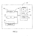
- FIG. 2 is a block diagram of a mobile device 200, which is an exemplary computing environment.
- Mobile device 200 includes a microprocessor 202, memory 204, input/output (I/O) components 206, and a communication interface 208 for communicating with remote computers or other mobile devices.
- I/O input/output
- the afore-mentioned components are coupled for communication with one another over a suitable bus 210.
- Memory 204 is implemented as non-volatile electronic memory such as random access memory (RAM) with a battery back-up module (not shown) such that information stored in memory 204 is not'lost when the general power to mobile device 200 is shut down.
- RAM random access memory
- a portion of memory 204 is preferably allocated as addressable memory for program execution, while another portion of memory 204 is preferably used for storage, such as to simulate storage on a disk drive.
- Memory 204 includes an operating system 212, application programs 214 as well as an object store 216.
- operating system 212 is preferably executed by processor 202 from memory 204.
- Operating system 212 in one preferred embodiment, is a WINDOWS® CE brand operating system commercially available from Microsoft Corporation.
- Operating system 212 is preferably designed for mobile devices, and implements database features that can be utilized by applications 214 through a set of exposed application programming interfaces and methods.
- the objects in object store 216 are maintained by applications 214 and operating system 212, at least partially in response to calls to the exposed application programming interfaces and methods.
- Communication interface 208 represents numerous devices and technologies that allow mobile device 200 to send and receive information.
- the devices include wired and wireless modems, satellite receivers and broadcast tuners to name a few.
- Mobile device 200 can also be directly connected to a computer to exchange data therewith.
- communication interface 208 can be an infrared transceiver or a serial or parallel communication connection, all of which are capable of transmitting streaming information.
- Input/output components 206 include a variety of input devices such as a touch-sensitive screen, buttons, rollers, and a microphone as well as a variety of output devices including an audio generator, a vibrating device, and a display.
- input devices such as a touch-sensitive screen, buttons, rollers, and a microphone
- output devices including an audio generator, a vibrating device, and a display.
- the devices listed above are by way of example and need not all be present on mobile device 200.
- other input/output devices may be attached to or found with mobile device 200 within the scope of the present invention.
- the present invention identifies a collection of scaling vectors, S k , and correction vectors, r k , that can be respectively multiplied by and added to a feature vector representing a portion of a noisy pattern signal to produce a feature vector representing a portion of a "clean" pattern signal.
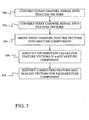
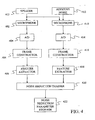
- a method for identifying the collection of scaling vectors and correction vectors is described below with reference to the flow diagram of FIG. 3 and the block diagram of FIG. 4 .
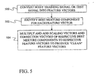
- a method of applying scaling vectors and correction vectors to noisy feature vectors is described below with reference to the flow diagram of FIG. 5 and the block diagram of FIG. 6 .
- the method of identifying scaling vectors and correction vectors begins in step 300 of FIG. 3 , where a "clean" channel signal is converted into a sequence of feature vectors.
- a speaker 400 of FIG. 4 speaks into a microphone 402, which converts the audio waves into electrical signals.
- the electrical signals are then sampled by an analog-to-digital converter 404 to generate a sequence of digital values, which are grouped into frames of values by a frame constructor 406.
- A-to-D converter 404 samples the analog signal at 16 kHz and 16 bits per sample, thereby creating 32 kilobytes of speech data per second and frame constructor 406 creates a new frame every 10 milliseconds that includes 25 milliseconds worth of data.
- Each frame of data provided by frame constructor 406 is converted into a feature vector by a feature extractor 408.
- feature extraction modules include modules for performing Linear Predictive Coding (LPC), LPC derived cepstrum, Perceptive Linear Prediction (PLP), Auditory model feature extraction, and Mel-Frequency Cepstrum Coefficients (MFCC) feature extraction. Note that the invention is not limited to these feature extraction modules and that other modules may be used within the context of the present invention.
- step 302 of FIG. 3 a noisy channel signal is converted into feature vectors.
- the conversion of step 302 is shown as occurring after the conversion of step 300, any part of the conversion may be performed before, during or after step 300 under the present invention.
- the conversion of step 302 is performed through a process similar to that described above for step 300.
- this process begins when the same speech signal generated by speaker 400 is provided to a second microphone 410.
- This second microphone also receives an additive noise signal from an additive noise source 412.
- Microphone 410 converts the speech and noise signals into a single electrical signal, which is sampled by an analog-to-digital converter 414.
- the sampling characteristics for A/D converter 414 are the same as those described above for A/D converter 404.
- the samples provided by A/D converter 414 are collected into frames by a frame constructor 416, which acts in a manner similar to frame constructor 406. These frames of samples are then converted into feature vectors by a feature extractor 418, which uses the same feature extraction method as feature extractor 408.
- microphone 410, A/D converter 414, frame constructor 416 and feature extractor 418 are not present. Instead, the additive noise is added to a stored version of the speech signal at some point within the processing chain formed by microphone 402, A/D converter 404, frame constructor 406, and feature extractor 408.
- the analog version of the "clean" channel signal may be stored after it is created by microphone 402. The original "clean" channel signal is then applied to A/D converter 404, frame constructor 406, and feature extractor 408.
- an analog noise signal is added to the stored "clean" channel signal to form a noisy analog channel signal. This noisy signal is then applied to A/D converter 404, frame constructor 406, and feature extractor 408 to form the feature vectors for the noisy channel signal.
- digital samples of noise are added to stored digital samples of the "clean" channel signal between A/D converter 404 and frame constructor 406, or frames of digital noise samples are added to stored frames of "clean” channel samples after frame constructor 406.
- the frames of "clean” channel samples are converted into the frequency domain and the spectral content of additive noise is added to the frequency-domain representation of the "clean” channel signal. This produces a frequency-domain representation of a noisy channel signal that can be used for feature extraction.
- noise reduction trainer 420 groups the feature vectors for the noisy channel signal into mixture components. This grouping can be done by grouping feature vectors of similar noises together using a maximum likelihood training technique or by grouping feature vectors that represent a temporal section of the speech signal together. Those skilled in the art will recognize that other techniques for grouping the feature vectors may be used and that the two techniques listed above are only provided as examples.
- noise reduction trainer 420 After the feature vectors of the noisy channel signal have been grouped into mixture components, noise reduction trainer 420 generates a set of distribution values that are indicative of the distribution of the feature vectors within the mixture component- This is shown as step 306 in FIG. 3 . In many embodiments, this involves determining a mean vector and a standard deviation vector for each vector component in the feature vectors of each mixture component. In an embodiment in which maximum likelihood training is used to group the feature vectors, the means and standard deviations are provided as by-products of identifying the groups for the mixture components.
- the noise reduction trainer 420 determines a correction vector, r k , and a scaling vector Sk, for each mixture component, k, at step 308 of FIG. 3 .
- the vector components of the scaling vector and the vector components of the correction vector for each mixture component are determined using a weighted least squares estimation technique.
- y i , t ⁇ y i , t ⁇ ⁇ i 0 T - 1 p k
- y i , t ⁇ x i , l ⁇ y i , t - ⁇ i 0 T - 1 p k
- y i , t ⁇ x i , t ⁇ ⁇ i 0 T - 1 p k
- y i , t ⁇ y i , t 2 ⁇ i 0 T - 1 p k
- y i , t ⁇ y i , t 2 - ⁇ i 0 T - 1 p k
- y i , t ⁇ y i , t 2 - ⁇ i 0 T - 1
- S i,k is the i th vector component of a scaling vector
- S k for mixture component k
- r i,k is the i th vector component of a correction vector
- r k for mixture component k
- y i,t is the i th vector component for the feature vector in the t th frame of the noisy channel signal
- x i,t is the i th vector component for the feature vector in the t th frame of the "clean" channel signal
- T is the total number of frames in the "clean” and noisy channel signals
- y i , t is the probability of the k th mixture component given the feature vector component for the t th frame of the noisy channel signal.
- y i , t term provides a weighting function that indicates the relative relationship between the k th mixture component and the current frame of the channel signals.
- y i , l term can be calculated using Bayes' theorem as: p k
- y i , t p y i , t
- k can be determined using a normal distribution based on the distribution values determined for the k th mixture component in step 306 of FIG. 3 .
- the probability of the k th mixture component, p ( k ) is simply the inverse of the number of mixture components. For example, in an embodiment that has 256 mixture components, the probability of any one mixture component is 1/256.
- the process of training the noise reduction system of the present invention is complete.
- the correction vectors, scaling vectors, and distribution values for each mixture component are then stored in a noise reduction parameter storage 422 of FIG. 4 .
- the vectors may be used in a noise reduction technique of the present invention.
- the correction vectors and scaling vectors may be used to remove noise in a training signal and/or test signal used in pattern recognition.
- FIG. 5 provides a flow diagram that describes the technique for reducing noise in a training signal and/or test signal.
- the process of FIG. 5 begins at step 500 where a noisy training signal or test signal is converted into a series of feature vectors.
- the noise reduction technique determines which mixture component best matches each noisy feature vector. This is done by applying the noisy feature vector to a distribution of noisy channel feature vectors associated with each mixture component. In one embodiment, this distribution is a collection of normal distributions defined by the mixture component's mean and standard deviation vectors. The mixture component that provides the highest probability for the noisy feature vector is then selected as the best match for the feature vector.
- k ⁇ arg k max c k ⁇ N y ; ⁇ k , ⁇ k
- k ⁇ is the best matching mixture component
- c k is a weight factor for the k th mixture component, N y
- ⁇ k , ⁇ k is the value for the individual noisy feature vector, y, from the normal distribution generated for the mean vector, ⁇ k , and the standard deviation vector, ⁇ k , of the k th mixture component.
- each mixture component is given an equal weight factor c k .
- the mean vector and standard deviation vector for each mixture component is determined from noisy channel. vectors and not "clean" channel vectors as was done in the prior art. Because of this, the normal distributions based on these means and standard deviations are better shaped for finding a best mixture component for a noisy pattern vector.
- x i S i , k ⁇ y i + r i , k
- x i the i th vector component of an individual "clean" feature vector
- y i the i th vector component of an individual noisy feature vector from the input signal
- S i,k and r i,k are the i th vector component of the scaling and correction vectors, respectively, both optimally selected for the individual noisy feature vector.
- Equation 5 is repeated for each vector component.
- FIG. 6 provides a block diagram of an environment in which the noise reduction technique of the present invention may be utilized.
- FIG. 6 shows a speech recognition system in which the noise reduction technique of the present invention is used to reduce noise in a training signal used to train an acoustic model and/or to reduce noise in a test signal that is applied against an acoustic model to identify the linguistic content of the test signal.
- a speaker 600 speaks into a microphone 604.
- Microphone 604 also receives additive noise from one or more noise sources 602.
- the audio signals detected by microphone 604 are converted into electrical signals that are provided to analog-to-digital converter 606.
- additive noise 602 is shown entering through microphone 604 in the embodiment of FIG. 6 , in other embodiments, additive noise 602 may be added to the input speech signal as a digital signal after A-to-D converter 606.
- A-to-D converter 606 converts the analog signal from microphone 604 into a series of digital values. In several embodiments, A-to-D converter 606 samples the analog signal at 16 kHz and 16 bits-per sample, thereby creating 32 kilobytes of speech data per second. These digital values are provided to a frame constructor 607, which, in one embodiment, groups the values into 25 millisecond frames that start 10 milliseconds apart.
- the frames of data created by frame constructor 607 are provided to feature extractor 610, which extracts a feature from each frame.
- feature extractor 610 which extracts a feature from each frame.
- the same feature extraction that was used to train the noise reduction parameters (the scaling vectors, correction vectors, means, and standard deviations of the mixture components) is used in feature extractor 610.
- examples of such feature extraction modules include modules for performing Linear Predictive Coding (LPC), LPC derived cepstrum, Perceptive Linear Prediction (PLP), Auditory model feature extraction, and Mel-Frequency Cepstrum Coefficients (MFCC) feature extraction.
- LPC Linear Predictive Coding
- PDP Perceptive Linear Prediction
- MFCC Mel-Frequency Cepstrum Coefficients
- the feature extraction module produces a stream of feature vectors that are each associated with a frame of the speech signal.
- This stream of feature vectors is provided to noise reduction module 610 of the present invention, which uses the noise reduction parameters stored in noise reduction parameter storage 611 to reduce the noise in the input speech signal.
- noise reduction module 610 selects a single mixture component for each input feature vector and then multiplies the input feature vector by that mixture component's scaling vector and adding that mixture component's correction vector to the product to produce a "clean" feature vector.
- the output of noise reduction module 610 is a series of "clean" feature vectors. If the input signal is a training signal, this series of "clean" feature vectors is provided to a trainer 624, which uses the "clean" feature vectors and a training text 626 to train an acoustic model 618. Techniques for training such models are known in the art and a description of them is not required for an understanding of the present invention.
- the "clean" feature vectors are provided to a decoder 612, which identifies a most likely sequence of words based on the stream of feature vectors, a lexicon 614, a language model 616, and the acoustic model 618.
- the particular method used for decoding is not important to the present invention and any of several known methods for decoding may be used.
- Confidence measure module 620 identifies which words are most likely to have been improperly identified by the speech recognizer, based in part on a secondary acoustic model(not shown). Confidence measure module 620 then provides the sequence of hypothesis words to an output module 622 along with identifiers indicating which words may have been improperly identified. Those skilled in the art will recognize that confidence measure module 620 is not necessary for the practice of the present invention.
- FIG. 6 depicts a speech recognition system
- the present invention may be used in any pattern recognition system and is not limited to speech.
Landscapes
- Engineering & Computer Science (AREA)
- Acoustics & Sound (AREA)
- Signal Processing (AREA)
- Health & Medical Sciences (AREA)
- Audiology, Speech & Language Pathology (AREA)
- Human Computer Interaction (AREA)
- Physics & Mathematics (AREA)
- Computational Linguistics (AREA)
- Quality & Reliability (AREA)
- Multimedia (AREA)
- Noise Elimination (AREA)
- Circuit For Audible Band Transducer (AREA)
- Soundproofing, Sound Blocking, And Sound Damping (AREA)
- Tone Control, Compression And Expansion, Limiting Amplitude (AREA)
- Excavating Of Shafts Or Tunnels (AREA)
- Drying Of Semiconductors (AREA)
- Inorganic Insulating Materials (AREA)
- Compression, Expansion, Code Conversion, And Decoders (AREA)
Claims (31)
- Verfahren zum Erzeugen von Korrekturvektoren, mit denen Rauschen aus einem Eingangssignal entfernt wird, wobei das Verfahren umfasst:Zugreifen auf eine Gruppe rauschbehafteter Kanalvektoren, die ein rauschbehaftetes Kanalsignal darstellen, das ein Sprachsignal ist;Zugreifen auf eine Gruppe störungsfreier Kanalvektoren, die ein störungsfreies Kanalsignal darstellen;Zusammenfassen (304) der rauschbehafteten Kanalvektoren zu einer Vielzahl von Mischungskomponenten; undBestimmen (308) eines Korrekturvektors und eines Skaliervektors für jede Mischungskomponente auf Basis der Gruppe rauschbehafteter Kanalvektoren und der Gruppe störungsfreier Kanalvektoren;wobei Zusammenfassen umfasst, dass die rauschbehafteten Kanalvektoren zusammengefasst werden, die einen zeitlichen Abschnitt des Sprachsignals darstellen.
- Verfahren nach Anspruch 1, wobei Bestimmen eines Korrekturvektors Anpassen einer Funktion auf Basis der rauschbehafteten Kanalvektoren an die störungsfreien Kanalvektoren umfasst.
- Verfahren nach Anspruch 2, wobei Anpassen einer Funktion Durchführen einer linearen Fehlerquadratberechnung umfasst.
- Verfahren nach Anspruch 3, wobei Durchführen einer linearen Fehlerquadratberechnung umfasst:Bestimmen eines Verteilungsparameters für jede Mischungskomponente, wobei der Verteilungsparameter die Verteilung rauschbehafteter Kanalvektoren beschreibt, die mit der jeweiligen Mischungskomponente zusammenhängen;Verwenden des Verteilungsparameters, um einen Gewicht-Wert auszubilden; undBenutzen des Gewicht-Wertes bei der linearen Fehlerquadratberechnung.
- Verfahren nach Anspruch 4, wobei Verwenden des Verteilungsparameters zum Ausbilden eines Gewicht-Wertes Verwenden des Verteilungsparameters zum Bestimmen einer Wahrscheinlichkeit einer Mischungskomponente umfasst, wenn ein verrauschter Kanalvektor gegeben ist.
- Verfahren nach Anspruch 1, wobei das Bestimmen Bestimmen eines additiven Korrekturvektors und eines Skalier-Korrekturvektors umfasst.
- Verfahren nach Anspruch 1, wobei Zusammenfassen der rauschbehafteten Kanalvektoren Bestimmen eines Verteilungsparameters für jede Mischungskomponente umfasst, der Verteilungsparameter die Verteilung rauschbehafteter Kanalvektoren beschreibt, die mit der jeweiligen Mischungskomponente zusammenhängen, und Bestimmen eines Korrekturvektors Bestimmen eines Korrekturvektors teilweise auf Basis der Verteilungsparameter umfasst.
- Verfahren nach Anspruch 1, das des Weiteren Verwenden des Korrekturvektors zum Entfernen von Rauschen aus einem Eingangssignal über einen Prozess umfasst, der umfasst:Umwandeln des Eingangssignals in Eingangsvektoren;Ermitteln einer am besten geeigneten Mischungskomponente für jeden Eingangsvektor; undfür jeden Eingangsvektor Anwenden eines Korrekturvektors, der mit der Mischungskomponente zusammenhängt, die am besten für den Eingangsvektor geeignet ist, auf den Eingangsvektor.
- Verfahren zum Reduzieren von Rauschen in einem rauschbehafteten Signal, wobei das Verfahren umfasst:Ausbilden von Mischungskomponenten mittels Durchführen aller Schritte des Verfahrens nach Anspruch 1;Identifizieren einer der Mischungskomponenten für einen rauschbehafteten Merkmalvektor, der einen Teil des rauschbehafteten Signals darstellt;Abrufen des Korrekturvektors und des Skaliervektors, die mit der identifizierten Mischungskomponente zusammenhängen;Multiplizieren des rauschbehafteten Merkmalvektors mit dem Skaliervektor, um einen skalierten Merkmalvektor auszubilden; undAddieren des Korrekturvektors zu dem skalierten Merkmalvektor, um einen störungsfreien Merkmalvektor auszubilden, der einen Teil eines störungsfreien Signals darstellt.
- Verfahren nach Anspruch 9, wobei Identifizieren einer Mischungskomponente Identifizieren einer wahrscheinlichsten Mischungskomponente für einen rauschbehafteten Merkmalvektor umfasst.
- Verfahren nach Anspruch 10, wobei Identifizieren einer wahrscheinlichsten Mischungskomponente umfasst:für jede Mischungskomponente Bestimmen einer Wahrscheinlichkeit des rauschbehafteten Merkmalvektors, wenn die Mischungskomponente gegeben ist; undAuswählen der Mischungskomponente, die die höchste Wahrscheinlichkeit bietet, als die wahrscheinlichste Mischungskomponente.
- Verfahren nach Anspruch 11, wobei Bestimmen einer Wahrscheinlichkeit Bestimmen einer Wahrscheinlichkeit auf Basis einer Verteilung rauschbehafteter Kanal-Merkmalvektoren umfasst, die der Mischungskomponente zugeordnet sind.
- Verfahren nach Anspruch 12, wobei Bestimmen einer Wahrscheinlichkeit auf Basis einer Verteilung Bestimmen einer Wahrscheinlichkeit auf Basis eines Mittelwertes und einer Standardabweichung der Verteilung umfasst.
- Verfahren nach Anspruch 9, wobei Abrufen eines Korrekturvektors und eines Skaliervektors Abrufen eines Korrekturvektors sowie eines Skaliervektors umfasst, die über Anpassen einer Funktion, die bezüglich einer Sequenz rauschbehafteter Kanal-Merkmalvektoren bewertet ist, an eine Sequenz störungsfreier Kanal-Merkmalvektoren ausgebildet werden.
- Verfahren nach Anspruch 14, wobei Anpassen der Funktion Durchführen einer linearen Fehlerquadratberechnung umfasst.
- Verfahren nach Anspruch 15, wobei Durchführen einer linearen Fehlerquadratberechnung Benutzen eines Gewicht-Wertes bei der linearen Fehlerquadratberechnung umfasst und der Gewicht-Wert eine Anzeige von Zusammenhang zwischen einem rauschbehafteten Kanal-Merkmalvektor und einer Mischungskomponente bereitstellt.
- Verfahren nach Anspruch 16, wobei Benutzen eines Gewicht-Wertes umfasst:Bestimmen einer bedingten Wahrscheinlichkeit einer Mischungskomponente, wenn ein rauschbehafteter Kanal-Merkmalvektor gegeben ist; undVerwenden der bedingten Wahrscheinlichkeit als den Gewicht-Wert.
- Verfahren nach Anspruch 17, wobei Bestimmen einer bedingten Wahrscheinlichkeit umfasst:für jede Mischungskomponente Bestimmen einer Wahrscheinlichkeit der Mischungskomponente und Bestimmen einer Merkmal-Wahrscheinlichkeit, die die Wahrscheinlichkeit des rauschbehafteten Kanal-Merkmalvektors darstellt, wenn die Mischungskomponente gegeben ist;für jede Mischungskomponente Multiplizieren der Wahrscheinlichkeit der Mischungskomponente mit der jeweiligen Merkmal-Wahrscheinlichkeit für die Mischungskomponente, um ein entsprechendes Wahrscheinlichkeits-Produkt zu schaffen;Summieren der Wahrscheinlichkeits-Produkte des rauschbehafteten Merkmalvektors für alle Mischungskomponenten, um eine Wahrscheinlichkeits-Summe zu erzeugen;Multiplizieren der Wahrscheinlichkeit der Mischungskomponente, die mit dem Korrekturvektor und dem Skaliervektor zusammenhängt, mit der Wahrscheinlichkeit des rauschbehafteten Merkmalvektors, wenn die Mischungskomponente gegeben ist, die mit dem Korrekturvektor und dem Skaliervektor zusammenhängt, um ein zweites Wahrscheinlichkeits-Produkt zu erzeugen; undDividieren des zweiten Wahrscheinlichkeits-Produktes durch die Wahrscheinlichkeits-Summe.
- Verfahren zum Reduzieren von Rauschen in einem rauschbehafteten Eingangssignal nach Anspruch 9, wobei das Abrufen Anpassen einer Funktion, die auf eine Sequenz rauschbehafteter Kanal-Merkmalvektoren angewendet wird, die ein rauschbehaftetes Kanalsignal darstellen, an eine Sequenz störungsfreier Kanal-Merkmalvektoren umfasst, die ein störungsfreies Kanalsignal darstellen, um wenigstens einen Korrekturvektor und wenigstens einen Skaliervektor zu bestimmen, wobei das Multiplizieren Multiplizieren des Skaliervektors mit jedem rauschbehafteten Eingangs-Merkmalvektor einer Sequenz rauschbehafteter Eingangs-Merkmalvektoren umfasst, die ein rauschbehaftetes Eingangssignal darstellen, um eine Sequenz skalierter Merkmalvektoren zu erzeugen, und wobei das Addieren Addieren eines Korrekturwertes zu jedem skalierten Merkmalvektor umfasst, um eine Sequenz störungsfreier Eingangs-Merkmalvektoren auszubilden, und die Sequenz störungsfreier Eingangs-Merkmalvektoren ein störungsfreies Eingangssignal darstellt, das weniger Rauschen aufweist als das rauschbehaftete Eingangssignal.
- Verfahren nach Anspruch 19, wobei Bestimmen wenigstens eines Korrekturvektors und wenigstens eines Skaliervektors Erzeugen einer Gruppe von Korrektur- und Skaliervektoren umfasst, und jeder Korrekturvektor sowie jeder Skaliervektor einer separaten Mischungskomponente der Sequenz rauschbehafteter Kanal-Merkmalvektoren entsprechen.
- Verfahren nach Anspruch 20, wobei Bestimmen eines Korrekturvektors umfasst:Zusammenfassen der rauschbehafteten Kanal-Merkmalvektoren zu wenigstens einer Mischungskomponente;Bestimmen eines Verteilungswertes, der die Verteilung der rauschbehafteten Kanal-Merkmalvektoren in wenigstens einer Mischungskomponente anzeigt; undVerwenden des Verteilungswertes für eine Mischungskomponente, um den Korrekturvektor und den Skaliervektor für diese Mischungskomponente zu bestimmen.
- Verfahren nach Anspruch 21, wobei Verwenden des Verteilungswertes zum Bestimmen eines Korrekturvektors und eines Skaliervektors für eine Mischungskomponente umfasst:für jeden rauschbehafteten Kanal-Merkmalvektor Bestimmen wenigstens einer bedingten Mischungs-Wahrscheinlichkeit, wobei die bedingte Mischungs-Wahrscheinlichkeit die Wahrscheinlichkeit der Mischungskomponente darstellt, wenn der rauschbehaftete Kanal-Merkmalvektor gegeben ist, und die bedingte Mischungs-Wahrscheinlichkeit teilweise auf einem Verteilungswert für die Mischungskomponente basiert; undAnwenden der bedingten Mischungs-Wahrscheinlichkeit in einer linearen Fehlerquadratberechnung.
- Verfahren nach Anspruch 22, wobei Bestimmen einer bedingten Mischungs-Wahrscheinlichkeit umfasst:Bestimmen einer bedingten Merkmalvektor-Wahrscheinlichkeit, die die Wahrscheinlichkeit eines rauschbehafteten Kanal-Merkmalvektors darstellt, wenn die Mischungskomponente gegeben ist, wobei die Wahrscheinlichkeit auf dem Verteilungswert für die Mischung basiert;Multiplizieren der bedingten Merkmalvektor-Wahrscheinlichkeit mit der unbedingten Wahrscheinlichkeit der Mischungskomponente, um ein Wahrscheinlichkeits-Produkt zu erzeugen; undDividieren des Wahrscheinlichkeits-Produkts durch die Summe der für alle Mischungskomponenten für den rauschbehafteten Kanal-Merkmalvektor erzeugten Wahrscheinlichkeits-Produkte.
- Verfahren nach Anspruch 23, wobei Bestimmen einer bedingten Merkmalvektor-Wahrscheinlichkeit Bestimmen der Wahrscheinlichkeit aus einer Normalverteilung umfasst, die aus dem Verteilungswert für eine Mischungskomponente ausgebildet wird.
- Verfahren nach Anspruch 24, wobei Bestimmen eines Verteilungswertes Bestimmen eines Mittelwert-Vektors und Bestimmen eines Standardabweichungs-Vektors umfasst.
- Verfahren nach Anspruch 20, wobei Multiplizieren des Skaliervektors mit jedem rauschbehafteten Eingangs-Merkmalvektor umfasst:Identifizieren einer Mischungskomponente für jeden rauschbehafteten Eingangs-Merkmalvektor; undMultiplizieren jedes rauschbehafteten Eingangs-Merkmalvektors mit einem Skaliervektor, der mit der Mischungskomponente zusammenhängt.
- Verfahren nach Anspruch 26, wobei Addieren eines Korrekturvektors Addieren eines Korrekturvektors, der mit der Mischungskomponente zusammenhängt, zu jedem skalierten Merkmalvektor umfasst.
- Verfahren nach Anspruch 27, wobei Identifizieren einer Mischungskomponente Identifizieren der wahrscheinlichsten Mischungskomponente für jeden rauschbehafteten Eingangs-Merkmalvektor umfasst.
- Verfahren nach Anspruch 28, wobei Identifizieren der wahrscheinlichsten Mischungskomponente umfasst:Zusammenfassen der rauschbehafteten Kanal-Merkmalvektoren zu wenigstens einer Mischungskomponente;Bestimmen eines Verteilungswertes, der die Verteilung der rauschbehafteten Kanal-Merkmalvektoren in wenigstens einer Mischungskomponente anzeigt;für jede Mischungskomponente Bestimmen einer Wahrscheinlichkeit des rauschbehafteten Eingangs-Merkmalvektors, wenn die Mischungskomponente gegeben ist, basierend auf einer Normalverteilung, die aus dem Verteilungswert für diese Mischungskomponente ausgebildet wird; undAuswählen der Mischungskomponente, die die höchste Wahrscheinlichkeit bietet, als die wahrscheinlichste Mischungskomponente.
- Computerlesbares Medium, das durch Computer ausführbare Befehle zum Reduzieren von Rauschen in einem Signal über Schritte umfasst, die umfassen:Verwenden eines Darstellungsvektors, der einen Teil des Signals darstellt, zum Identifizieren einer optimalen Mischungskomponente für diesen Teil;Auswählen eines Korrekturvektors und eines Skaliervektors, die mit der identifizierten optimalen Mischungskomponente zusammenhängen;Multiplizieren des Skaliervektors mit dem Darstellungsvektor, um ein Produkt auszubilden; undAddieren des Produktes zu dem Korrekturvektor, um einen rauschreduzierten Vektor auszubilden, der einen Teil eines rauschreduzierten Signals darstellt;wobei die optimale Mischungskomponente eine einer Vielzahl von Mischungskomponenten umfasst, die ausgebildet werden, indem Merkmalvektoren eines rauschbehafteten Kanalsignals zusammengefasst werden, das ein Sprachsignal ist, und die Merkmalvektoren zusammen einen zeitlichen Abschnitt des Sprachsignals darstellen.
- Computerlesbares Medium nach Anspruch 30, wobei der Schritt des Verwendens eines Darstellungsvektors zum Identifizieren einer optimalen Mischungskomponente umfasst:für jede Mischungskomponente Anwenden des Darstellungsvektors auf eine Verteilung von Darstellungsvektoren, die mit der Mischungskomponente verknüpft sind, um eine Likelihood des Darstellungsvektors zu erzeugen, wenn die Mischungskomponente gegeben ist; undAuswählen der Mischungskomponente, die die größte Likelihood erzeugt, als die optimale Mischungskomponente.
Applications Claiming Priority (2)
| Application Number | Priority Date | Filing Date | Title |
|---|---|---|---|
| US688764 | 2000-10-16 | ||
| US09/688,764 US7003455B1 (en) | 2000-10-16 | 2000-10-16 | Method of noise reduction using correction and scaling vectors with partitioning of the acoustic space in the domain of noisy speech |
Publications (3)
| Publication Number | Publication Date |
|---|---|
| EP1199712A2 EP1199712A2 (de) | 2002-04-24 |
| EP1199712A3 EP1199712A3 (de) | 2003-09-10 |
| EP1199712B1 true EP1199712B1 (de) | 2009-11-25 |
Family
ID=24765679
Family Applications (1)
| Application Number | Title | Priority Date | Filing Date |
|---|---|---|---|
| EP01124142A Expired - Lifetime EP1199712B1 (de) | 2000-10-16 | 2001-10-10 | Verfahren zur Geräuschunterdrückung |
Country Status (5)
| Country | Link |
|---|---|
| US (2) | US7003455B1 (de) |
| EP (1) | EP1199712B1 (de) |
| JP (1) | JP3939955B2 (de) |
| AT (1) | ATE450033T1 (de) |
| DE (1) | DE60140595D1 (de) |
Cited By (1)
| Publication number | Priority date | Publication date | Assignee | Title |
|---|---|---|---|---|
| US7890322B2 (en) | 2008-03-20 | 2011-02-15 | Huawei Technologies Co., Ltd. | Method and apparatus for speech signal processing |
Families Citing this family (11)
| Publication number | Priority date | Publication date | Assignee | Title |
|---|---|---|---|---|
| JP4169921B2 (ja) * | 2000-09-29 | 2008-10-22 | パイオニア株式会社 | 音声認識システム |
| US6959276B2 (en) * | 2001-09-27 | 2005-10-25 | Microsoft Corporation | Including the category of environmental noise when processing speech signals |
| US7117148B2 (en) | 2002-04-05 | 2006-10-03 | Microsoft Corporation | Method of noise reduction using correction vectors based on dynamic aspects of speech and noise normalization |
| US7174292B2 (en) * | 2002-05-20 | 2007-02-06 | Microsoft Corporation | Method of determining uncertainty associated with acoustic distortion-based noise reduction |
| US7103540B2 (en) | 2002-05-20 | 2006-09-05 | Microsoft Corporation | Method of pattern recognition using noise reduction uncertainty |
| US7107210B2 (en) * | 2002-05-20 | 2006-09-12 | Microsoft Corporation | Method of noise reduction based on dynamic aspects of speech |
| DE102004017486A1 (de) * | 2004-04-08 | 2005-10-27 | Siemens Ag | Verfahren zur Geräuschreduktion bei einem Sprach-Eingangssignal |
| US20070055519A1 (en) * | 2005-09-02 | 2007-03-08 | Microsoft Corporation | Robust bandwith extension of narrowband signals |
| US8615393B2 (en) * | 2006-11-15 | 2013-12-24 | Microsoft Corporation | Noise suppressor for speech recognition |
| KR100911429B1 (ko) * | 2007-08-22 | 2009-08-11 | 한국전자통신연구원 | 환경 이동을 위한 잡음 적응형 음향 모델 생성 방법 및 장치 |
| US10319390B2 (en) * | 2016-02-19 | 2019-06-11 | New York University | Method and system for multi-talker babble noise reduction |
Family Cites Families (22)
| Publication number | Priority date | Publication date | Assignee | Title |
|---|---|---|---|---|
| US629277A (en) * | 1899-02-01 | 1899-07-18 | William J Slack | Cistern. |
| US4718094A (en) * | 1984-11-19 | 1988-01-05 | International Business Machines Corp. | Speech recognition system |
| US4852181A (en) * | 1985-09-26 | 1989-07-25 | Oki Electric Industry Co., Ltd. | Speech recognition for recognizing the catagory of an input speech pattern |
| US4926488A (en) | 1987-07-09 | 1990-05-15 | International Business Machines Corporation | Normalization of speech by adaptive labelling |
| IL84948A0 (en) * | 1987-12-25 | 1988-06-30 | D S P Group Israel Ltd | Noise reduction system |
| US5390278A (en) * | 1991-10-08 | 1995-02-14 | Bell Canada | Phoneme based speech recognition |
| DE4309985A1 (de) | 1993-03-29 | 1994-10-06 | Sel Alcatel Ag | Geräuschreduktion zur Spracherkennung |
| DE4322372A1 (de) | 1993-07-06 | 1995-01-12 | Sel Alcatel Ag | Verfahren und Vorrichtung zur Spracherkennung |
| US5590242A (en) * | 1994-03-24 | 1996-12-31 | Lucent Technologies Inc. | Signal bias removal for robust telephone speech recognition |
| US5604839A (en) | 1994-07-29 | 1997-02-18 | Microsoft Corporation | Method and system for improving speech recognition through front-end normalization of feature vectors |
| US6067517A (en) | 1996-02-02 | 2000-05-23 | International Business Machines Corporation | Transcription of speech data with segments from acoustically dissimilar environments |
| US6446038B1 (en) * | 1996-04-01 | 2002-09-03 | Qwest Communications International, Inc. | Method and system for objectively evaluating speech |
| US6026359A (en) | 1996-09-20 | 2000-02-15 | Nippon Telegraph And Telephone Corporation | Scheme for model adaptation in pattern recognition based on Taylor expansion |
| GB2319379A (en) * | 1996-11-18 | 1998-05-20 | Secr Defence | Speech processing system |
| US5950157A (en) | 1997-02-28 | 1999-09-07 | Sri International | Method for establishing handset-dependent normalizing models for speaker recognition |
| US6490555B1 (en) * | 1997-03-14 | 2002-12-03 | Scansoft, Inc. | Discriminatively trained mixture models in continuous speech recognition |
| US5924065A (en) * | 1997-06-16 | 1999-07-13 | Digital Equipment Corporation | Environmently compensated speech processing |
| CA2216224A1 (en) * | 1997-09-19 | 1999-03-19 | Peter R. Stubley | Block algorithm for pattern recognition |
| US6148284A (en) * | 1998-02-23 | 2000-11-14 | At&T Corporation | Method and apparatus for automatic speech recognition using Markov processes on curves |
| US6202047B1 (en) * | 1998-03-30 | 2001-03-13 | At&T Corp. | Method and apparatus for speech recognition using second order statistics and linear estimation of cepstral coefficients |
| KR100304666B1 (ko) * | 1999-08-28 | 2001-11-01 | 윤종용 | 음성 향상 방법 |
| US6529872B1 (en) | 2000-04-18 | 2003-03-04 | Matsushita Electric Industrial Co., Ltd. | Method for noise adaptation in automatic speech recognition using transformed matrices |
-
2000
- 2000-10-16 US US09/688,764 patent/US7003455B1/en not_active Expired - Fee Related
-
2001
- 2001-10-10 AT AT01124142T patent/ATE450033T1/de not_active IP Right Cessation
- 2001-10-10 DE DE60140595T patent/DE60140595D1/de not_active Expired - Lifetime
- 2001-10-10 EP EP01124142A patent/EP1199712B1/de not_active Expired - Lifetime
- 2001-10-16 JP JP2001317520A patent/JP3939955B2/ja not_active Expired - Lifetime
-
2005
- 2005-02-16 US US11/059,036 patent/US7254536B2/en not_active Expired - Fee Related
Non-Patent Citations (1)
| Title |
|---|
| YUNXIN ZHAO: "Frequency-Domain Maximum Likelihood Estimation for Automatic Speech Recognition in Additive and Convolutive Noises", IEEE TRANSACTIONS ON SPEECH AND AUDIO PROCESSING, vol. 8, no. 3, 31 May 2000 (2000-05-31), DETROIT, MI, USA, pages 255 - 266 * |
Cited By (1)
| Publication number | Priority date | Publication date | Assignee | Title |
|---|---|---|---|---|
| US7890322B2 (en) | 2008-03-20 | 2011-02-15 | Huawei Technologies Co., Ltd. | Method and apparatus for speech signal processing |
Also Published As
| Publication number | Publication date |
|---|---|
| EP1199712A3 (de) | 2003-09-10 |
| JP3939955B2 (ja) | 2007-07-04 |
| US7254536B2 (en) | 2007-08-07 |
| US7003455B1 (en) | 2006-02-21 |
| DE60140595D1 (de) | 2010-01-07 |
| ATE450033T1 (de) | 2009-12-15 |
| US20050149325A1 (en) | 2005-07-07 |
| EP1199712A2 (de) | 2002-04-24 |
| JP2002140093A (ja) | 2002-05-17 |
Similar Documents
| Publication | Publication Date | Title |
|---|---|---|
| EP2431972B1 (de) | Verfahren und Vorrichtung zur multisensorischen Sprachverstärkung | |
| US7107210B2 (en) | Method of noise reduction based on dynamic aspects of speech | |
| EP1396845B1 (de) | Verfahren zur iterativen Geräuschschätzung in einem rekursiven Zusammenhang | |
| EP1199708B1 (de) | Rauschrobuste Mustererkennung | |
| US7181390B2 (en) | Noise reduction using correction vectors based on dynamic aspects of speech and noise normalization | |
| US7769582B2 (en) | Method of pattern recognition using noise reduction uncertainty | |
| US6959276B2 (en) | Including the category of environmental noise when processing speech signals | |
| EP1465160B1 (de) | Verfahren zur Rauschabschätzung mittels inkrementellen Bayes'schen Lernens | |
| EP1508893B1 (de) | Rauschunterdrückungsverfahren unter Verwendung eines Signal-Rauschverhältnisses als optimal abzuschätzende Hauptgrösse | |
| US20030225577A1 (en) | Method of determining uncertainty associated with acoustic distortion-based noise reduction | |
| US6944590B2 (en) | Method of iterative noise estimation in a recursive framework | |
| US7003455B1 (en) | Method of noise reduction using correction and scaling vectors with partitioning of the acoustic space in the domain of noisy speech |
Legal Events
| Date | Code | Title | Description |
|---|---|---|---|
| PUAI | Public reference made under article 153(3) epc to a published international application that has entered the european phase |
Free format text: ORIGINAL CODE: 0009012 |
|
| AK | Designated contracting states |
Kind code of ref document: A2 Designated state(s): AT BE CH CY DE DK ES FI FR GB GR IE IT LI LU MC NL PT SE TR |
|
| AX | Request for extension of the european patent |
Free format text: AL;LT;LV;MK;RO;SI |
|
| PUAL | Search report despatched |
Free format text: ORIGINAL CODE: 0009013 |
|
| AK | Designated contracting states |
Kind code of ref document: A3 Designated state(s): AT BE CH CY DE DK ES FI FR GB GR IE IT LI LU MC NL PT SE TR |
|
| AX | Request for extension of the european patent |
Extension state: AL LT LV MK RO SI |
|
| RIC1 | Information provided on ipc code assigned before grant |
Ipc: 7G 10L 15/20 B Ipc: 7G 10L 21/02 A |
|
| 17P | Request for examination filed |
Effective date: 20040127 |
|
| AKX | Designation fees paid |
Designated state(s): AT BE CH CY DE DK ES FI FR GB GR IE IT LI LU MC NL PT SE TR |
|
| 17Q | First examination report despatched |
Effective date: 20041229 |
|
| 17Q | First examination report despatched |
Effective date: 20041229 |
|
| GRAP | Despatch of communication of intention to grant a patent |
Free format text: ORIGINAL CODE: EPIDOSNIGR1 |
|
| GRAS | Grant fee paid |
Free format text: ORIGINAL CODE: EPIDOSNIGR3 |
|
| GRAA | (expected) grant |
Free format text: ORIGINAL CODE: 0009210 |
|
| AK | Designated contracting states |
Kind code of ref document: B1 Designated state(s): AT BE CH CY DE DK ES FI FR GB GR IE IT LI LU MC NL PT SE TR |
|
| REG | Reference to a national code |
Ref country code: GB Ref legal event code: FG4D |
|
| REG | Reference to a national code |
Ref country code: CH Ref legal event code: EP |
|
| REG | Reference to a national code |
Ref country code: IE Ref legal event code: FG4D |
|
| REF | Corresponds to: |
Ref document number: 60140595 Country of ref document: DE Date of ref document: 20100107 Kind code of ref document: P |
|
| REG | Reference to a national code |
Ref country code: NL Ref legal event code: VDEP Effective date: 20091125 |
|
| PG25 | Lapsed in a contracting state [announced via postgrant information from national office to epo] |
Ref country code: SE Free format text: LAPSE BECAUSE OF FAILURE TO SUBMIT A TRANSLATION OF THE DESCRIPTION OR TO PAY THE FEE WITHIN THE PRESCRIBED TIME-LIMIT Effective date: 20091125 Ref country code: PT Free format text: LAPSE BECAUSE OF FAILURE TO SUBMIT A TRANSLATION OF THE DESCRIPTION OR TO PAY THE FEE WITHIN THE PRESCRIBED TIME-LIMIT Effective date: 20100325 Ref country code: FI Free format text: LAPSE BECAUSE OF FAILURE TO SUBMIT A TRANSLATION OF THE DESCRIPTION OR TO PAY THE FEE WITHIN THE PRESCRIBED TIME-LIMIT Effective date: 20091125 |
|
| PG25 | Lapsed in a contracting state [announced via postgrant information from national office to epo] |
Ref country code: CY Free format text: LAPSE BECAUSE OF FAILURE TO SUBMIT A TRANSLATION OF THE DESCRIPTION OR TO PAY THE FEE WITHIN THE PRESCRIBED TIME-LIMIT Effective date: 20091125 |
|
| PG25 | Lapsed in a contracting state [announced via postgrant information from national office to epo] |
Ref country code: BE Free format text: LAPSE BECAUSE OF FAILURE TO SUBMIT A TRANSLATION OF THE DESCRIPTION OR TO PAY THE FEE WITHIN THE PRESCRIBED TIME-LIMIT Effective date: 20091125 Ref country code: AT Free format text: LAPSE BECAUSE OF FAILURE TO SUBMIT A TRANSLATION OF THE DESCRIPTION OR TO PAY THE FEE WITHIN THE PRESCRIBED TIME-LIMIT Effective date: 20091125 |
|
| PG25 | Lapsed in a contracting state [announced via postgrant information from national office to epo] |
Ref country code: NL Free format text: LAPSE BECAUSE OF FAILURE TO SUBMIT A TRANSLATION OF THE DESCRIPTION OR TO PAY THE FEE WITHIN THE PRESCRIBED TIME-LIMIT Effective date: 20091125 Ref country code: DK Free format text: LAPSE BECAUSE OF FAILURE TO SUBMIT A TRANSLATION OF THE DESCRIPTION OR TO PAY THE FEE WITHIN THE PRESCRIBED TIME-LIMIT Effective date: 20091125 Ref country code: ES Free format text: LAPSE BECAUSE OF FAILURE TO SUBMIT A TRANSLATION OF THE DESCRIPTION OR TO PAY THE FEE WITHIN THE PRESCRIBED TIME-LIMIT Effective date: 20100308 |
|
| PLBE | No opposition filed within time limit |
Free format text: ORIGINAL CODE: 0009261 |
|
| STAA | Information on the status of an ep patent application or granted ep patent |
Free format text: STATUS: NO OPPOSITION FILED WITHIN TIME LIMIT |
|
| PG25 | Lapsed in a contracting state [announced via postgrant information from national office to epo] |
Ref country code: GR Free format text: LAPSE BECAUSE OF FAILURE TO SUBMIT A TRANSLATION OF THE DESCRIPTION OR TO PAY THE FEE WITHIN THE PRESCRIBED TIME-LIMIT Effective date: 20100226 |
|
| PGFP | Annual fee paid to national office [announced via postgrant information from national office to epo] |
Ref country code: MC Payment date: 20100929 Year of fee payment: 10 |
|
| 26N | No opposition filed |
Effective date: 20100826 |
|
| PGFP | Annual fee paid to national office [announced via postgrant information from national office to epo] |
Ref country code: NL Payment date: 20101009 Year of fee payment: 10 Ref country code: IE Payment date: 20101015 Year of fee payment: 10 |
|
| PGFP | Annual fee paid to national office [announced via postgrant information from national office to epo] |
Ref country code: LU Payment date: 20101111 Year of fee payment: 10 Ref country code: CH Payment date: 20101012 Year of fee payment: 10 |
|
| PG25 | Lapsed in a contracting state [announced via postgrant information from national office to epo] |
Ref country code: MC Free format text: LAPSE BECAUSE OF NON-PAYMENT OF DUE FEES Effective date: 20111031 |
|
| REG | Reference to a national code |
Ref country code: CH Ref legal event code: PL |
|
| PG25 | Lapsed in a contracting state [announced via postgrant information from national office to epo] |
Ref country code: CH Free format text: LAPSE BECAUSE OF NON-PAYMENT OF DUE FEES Effective date: 20111031 Ref country code: LI Free format text: LAPSE BECAUSE OF NON-PAYMENT OF DUE FEES Effective date: 20111031 |
|
| REG | Reference to a national code |
Ref country code: IE Ref legal event code: MM4A |
|
| PG25 | Lapsed in a contracting state [announced via postgrant information from national office to epo] |
Ref country code: TR Free format text: LAPSE BECAUSE OF FAILURE TO SUBMIT A TRANSLATION OF THE DESCRIPTION OR TO PAY THE FEE WITHIN THE PRESCRIBED TIME-LIMIT Effective date: 20091125 Ref country code: IE Free format text: LAPSE BECAUSE OF NON-PAYMENT OF DUE FEES Effective date: 20111010 |
|
| PG25 | Lapsed in a contracting state [announced via postgrant information from national office to epo] |
Ref country code: LU Free format text: LAPSE BECAUSE OF NON-PAYMENT OF DUE FEES Effective date: 20111010 |
|
| REG | Reference to a national code |
Ref country code: DE Ref legal event code: R082 Ref document number: 60140595 Country of ref document: DE Representative=s name: GRUENECKER, KINKELDEY, STOCKMAIR & SCHWANHAEUS, DE |
|
| REG | Reference to a national code |
Ref country code: GB Ref legal event code: 732E Free format text: REGISTERED BETWEEN 20150108 AND 20150114 |
|
| REG | Reference to a national code |
Ref country code: DE Ref legal event code: R081 Ref document number: 60140595 Country of ref document: DE Owner name: MICROSOFT TECHNOLOGY LICENSING, LLC, REDMOND, US Free format text: FORMER OWNER: MICROSOFT CORP., REDMOND, WASH., US Effective date: 20150126 Ref country code: DE Ref legal event code: R082 Ref document number: 60140595 Country of ref document: DE Representative=s name: GRUENECKER PATENT- UND RECHTSANWAELTE PARTG MB, DE Effective date: 20150126 |
|
| REG | Reference to a national code |
Ref country code: FR Ref legal event code: TP Owner name: MICROSOFT TECHNOLOGY LICENSING, LLC, US Effective date: 20150724 |
|
| REG | Reference to a national code |
Ref country code: FR Ref legal event code: PLFP Year of fee payment: 16 |
|
| REG | Reference to a national code |
Ref country code: FR Ref legal event code: PLFP Year of fee payment: 17 |
|
| REG | Reference to a national code |
Ref country code: FR Ref legal event code: PLFP Year of fee payment: 18 |
|
| PGFP | Annual fee paid to national office [announced via postgrant information from national office to epo] |
Ref country code: FR Payment date: 20180913 Year of fee payment: 18 |
|
| PGFP | Annual fee paid to national office [announced via postgrant information from national office to epo] |
Ref country code: DE Payment date: 20180925 Year of fee payment: 18 |
|
| PGFP | Annual fee paid to national office [announced via postgrant information from national office to epo] |
Ref country code: IT Payment date: 20181018 Year of fee payment: 18 Ref country code: GB Payment date: 20181010 Year of fee payment: 18 |
|
| REG | Reference to a national code |
Ref country code: DE Ref legal event code: R119 Ref document number: 60140595 Country of ref document: DE |
|
| PG25 | Lapsed in a contracting state [announced via postgrant information from national office to epo] |
Ref country code: DE Free format text: LAPSE BECAUSE OF NON-PAYMENT OF DUE FEES Effective date: 20200501 |
|
| GBPC | Gb: european patent ceased through non-payment of renewal fee |
Effective date: 20191010 |
|
| PG25 | Lapsed in a contracting state [announced via postgrant information from national office to epo] |
Ref country code: FR Free format text: LAPSE BECAUSE OF NON-PAYMENT OF DUE FEES Effective date: 20191031 Ref country code: GB Free format text: LAPSE BECAUSE OF NON-PAYMENT OF DUE FEES Effective date: 20191010 Ref country code: IT Free format text: LAPSE BECAUSE OF NON-PAYMENT OF DUE FEES Effective date: 20191010 |