EP1199503A1 - Struktur zum Zusammenhalten mehrerer flexibler Rohre mit Hilfe einer Ummantelung - Google Patents
Struktur zum Zusammenhalten mehrerer flexibler Rohre mit Hilfe einer Ummantelung Download PDFInfo
- Publication number
- EP1199503A1 EP1199503A1 EP01830568A EP01830568A EP1199503A1 EP 1199503 A1 EP1199503 A1 EP 1199503A1 EP 01830568 A EP01830568 A EP 01830568A EP 01830568 A EP01830568 A EP 01830568A EP 1199503 A1 EP1199503 A1 EP 1199503A1
- Authority
- EP
- European Patent Office
- Prior art keywords
- tubes
- sheath
- separate
- tube
- saudering
- Prior art date
- Legal status (The legal status is an assumption and is not a legal conclusion. Google has not performed a legal analysis and makes no representation as to the accuracy of the status listed.)
- Granted
Links
- 239000000463 material Substances 0.000 claims abstract description 15
- 239000000126 substance Substances 0.000 claims abstract description 6
- 230000001464 adherent effect Effects 0.000 claims description 2
- 239000012815 thermoplastic material Substances 0.000 claims description 2
- 230000004927 fusion Effects 0.000 claims 1
- 238000005304 joining Methods 0.000 abstract description 9
- 238000009413 insulation Methods 0.000 abstract description 3
- 230000000704 physical effect Effects 0.000 abstract description 2
- 239000004020 conductor Substances 0.000 description 3
- 238000001125 extrusion Methods 0.000 description 3
- 239000002131 composite material Substances 0.000 description 2
- 238000004519 manufacturing process Methods 0.000 description 2
- 238000000034 method Methods 0.000 description 2
- 239000004033 plastic Substances 0.000 description 2
- 239000004576 sand Substances 0.000 description 2
- 238000003860 storage Methods 0.000 description 2
- 238000004078 waterproofing Methods 0.000 description 2
- 230000005540 biological transmission Effects 0.000 description 1
- 230000015572 biosynthetic process Effects 0.000 description 1
- 238000004140 cleaning Methods 0.000 description 1
- 238000009833 condensation Methods 0.000 description 1
- 230000005494 condensation Effects 0.000 description 1
- 230000007797 corrosion Effects 0.000 description 1
- 238000005260 corrosion Methods 0.000 description 1
- 230000008878 coupling Effects 0.000 description 1
- 238000010168 coupling process Methods 0.000 description 1
- 238000005859 coupling reaction Methods 0.000 description 1
- 238000005520 cutting process Methods 0.000 description 1
- 230000005611 electricity Effects 0.000 description 1
- 238000005516 engineering process Methods 0.000 description 1
- 239000012530 fluid Substances 0.000 description 1
- 238000003780 insertion Methods 0.000 description 1
- 230000037431 insertion Effects 0.000 description 1
- 239000002184 metal Substances 0.000 description 1
- 238000000926 separation method Methods 0.000 description 1
- 238000003856 thermoforming Methods 0.000 description 1
- 230000003313 weakening effect Effects 0.000 description 1
Images
Classifications
-
- H—ELECTRICITY
- H02—GENERATION; CONVERSION OR DISTRIBUTION OF ELECTRIC POWER
- H02G—INSTALLATION OF ELECTRIC CABLES OR LINES, OR OF COMBINED OPTICAL AND ELECTRIC CABLES OR LINES
- H02G9/00—Installations of electric cables or lines in or on the ground or water
- H02G9/06—Installations of electric cables or lines in or on the ground or water in underground tubes or conduits; Tubes or conduits therefor
-
- F—MECHANICAL ENGINEERING; LIGHTING; HEATING; WEAPONS; BLASTING
- F16—ENGINEERING ELEMENTS AND UNITS; GENERAL MEASURES FOR PRODUCING AND MAINTAINING EFFECTIVE FUNCTIONING OF MACHINES OR INSTALLATIONS; THERMAL INSULATION IN GENERAL
- F16L—PIPES; JOINTS OR FITTINGS FOR PIPES; SUPPORTS FOR PIPES, CABLES OR PROTECTIVE TUBING; MEANS FOR THERMAL INSULATION IN GENERAL
- F16L1/00—Laying or reclaiming pipes; Repairing or joining pipes on or under water
- F16L1/024—Laying or reclaiming pipes on land, e.g. above the ground
- F16L1/06—Accessories therefor, e.g. anchors
- F16L1/11—Accessories therefor, e.g. anchors for the detection or protection of pipes in the ground
Definitions
- the invention consists of a structure having more than one flexible tube, which are kept together by a sheath, said structure is usually placed in ditches and is used to connect distant points of a territory.
- the tubes usually made of plastic and flexible material, must be placed side by side in groups and must be carefully laid down to avoid being deformed and in particular of being pressed down which would prevent the subsequent insertion of conductors or fluids for which they are designed.
- separate groups of tubes ⁇ each group usually consisting of three tubes ⁇ are placed on the sides of the ditch, therefore the tubes in each group are fixed with strips that are placed at a distance of a few metres from each other, and once they are joined, they are laid down within the ditch made to contain them.
- Said groups usually more than one, are placed one on top of the other and separated by a layer of sand which is used to form a soft bottom layer and also a separating layer, then the ditch is filled with the layer of concrete and is finally covered with gravel.
- Qualified personnel is essential for these operations therefore the operations of laying down and joining of the tubes, from distant points of the territory that need to be joined, are very costly.
- the disadvantages of said product are therefore an elevated production cost due to the slow outgoing movement of the machine that produces it; the imperfect consistency of the geometric characteristics of the product which originates weak points, and in any case the non uniformity of technical characteristics and the imperfect linearity of the product; the need, when installing it, to separate the component tubes at their ends to allow a cascade connection of the corresponding ones, with a longitudinal cut, to carry out the separation, which causes their weakening and possible breaks and slits.
- the aim of the present invention is a structure made of more than one tube, aligned side by side, which can be produced fast. Another aim is that of obtaining a structure with consistent physical and geometrical characteristics. One more aim is to obtain a product with an elevated capacity to insulate its contents and which allows a fast and secure cascade connection of corresponding tubes.
- the invention which has allowed to obtain said results consists of a structure in which several distinct tubes placed side by side are combined with a joining sheath of flexible material, which is adequate to maintain the tubes reciprocally positioned and separate, having suitable chemical and physical features that increase the insulation and protection of the content of each tube from the environment in which the invention will be placed, and also appropriate to protect the ends of the tubes to facilitate the cascade connections in said structures.
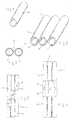
- the invention consists of a composite structure 1, in which several separate tubes 2, are combined and placed side by side but not attached to each other, and a sheath 3, of flexible and resistant material, which is adequate to wrap the tubes 2 separately, to protect them and to maintain them respectively in place so as to handle them as a single piece during the phases of storage, transportation and their placing in the ditch in which they are normally placed and then covered.
- the tubes 2 operate independently one from the other or from others, therefore they can be different from each other even if they are usually alike, at least in size.
- Each one shall be made of material that usually originates from plastic and that is the most suitable based on the function it has to carry out when installed.
- Each component tube 2 can therefore have different physical and chemical characteristics and is recognisable at least due to the colour or to a thread like element laid down within them, usually to facilitate the connections of the ends of the corresponding tubes during the assembly of the separate sections that realise the connection of far away points.
- Each tube can be individually protected by sheaths and/or by layers of material adequate to confer the necessary technical qualities to it.
- the combination of tubes 2, each one having the required technical characteristics, is stabilised by the wrapping sheath 3, which adheres to each single tube 2 and also with a welded line or saudering points 4 which separate the adjacent tubes.
- Said wrapping sheath 3 is made from suitable materials and in particular with thermoplastic material stamped and welded along the lines or points 4. It can be applied by extrusion on joined tubes 2, with aspiration of the air and thermoforming by saudering along lines or points 4 with methods that are technically known.
- Said sheath 3 will normally have a fusing or saudering temperature which shall be lower than the corresponding temperatures of the single tubes 2, so that, after the joining they remain adherent but separate.
- the material with which sheath 3 is realised and the material with which the tubes 2 are realised are not compatible for saudering, therefore remaining separate independently from the temperatures adopted during their joining.
- the composite structure therefore forms the conditions that facilitate the protection of the tubes during storage, transportation and positioning in the ditch, and also during the phases in which the corresponding tubes of consecutive sections must be prepared to be joined, therefore separated by sheath 3 that protects them and then separates them reciprocally for the application of the joining means, which are usually special sleeves.
Landscapes
- Engineering & Computer Science (AREA)
- General Engineering & Computer Science (AREA)
- Mechanical Engineering (AREA)
- Rigid Pipes And Flexible Pipes (AREA)
- Joints Allowing Movement (AREA)
- Supports For Pipes And Cables (AREA)
- Thermal Insulation (AREA)
Applications Claiming Priority (2)
| Application Number | Priority Date | Filing Date | Title |
|---|---|---|---|
| IT2000AR000018U IT251003Y1 (it) | 2000-10-20 | 2000-10-20 | Struttura a piu' tubi flessibili uniti da guaina |
| ITAR000018U | 2000-10-20 |
Publications (2)
| Publication Number | Publication Date |
|---|---|
| EP1199503A1 true EP1199503A1 (de) | 2002-04-24 |
| EP1199503B1 EP1199503B1 (de) | 2008-05-14 |
Family
ID=11437545
Family Applications (1)
| Application Number | Title | Priority Date | Filing Date |
|---|---|---|---|
| EP01830568A Expired - Lifetime EP1199503B1 (de) | 2000-10-20 | 2001-09-07 | Struktur zum Zusammenhalten mehrerer flexibler Rohre mit Hilfe einer Ummantelung |
Country Status (4)
| Country | Link |
|---|---|
| EP (1) | EP1199503B1 (de) |
| AT (1) | ATE395547T1 (de) |
| DE (1) | DE60133979D1 (de) |
| IT (1) | IT251003Y1 (de) |
Cited By (2)
| Publication number | Priority date | Publication date | Assignee | Title |
|---|---|---|---|---|
| DE20315371U1 (de) * | 2003-10-02 | 2005-02-17 | Thinxxs Gmbh | Verbinder zur Herstellung von Fluidverbindungen |
| CN103943195A (zh) * | 2014-04-26 | 2014-07-23 | 芜湖航天特种电缆厂 | 扁电缆 |
Citations (3)
| Publication number | Priority date | Publication date | Assignee | Title |
|---|---|---|---|---|
| GB1434015A (en) * | 1972-07-12 | 1976-04-28 | Post Office | Marking cables and pipes |
| FR2291443A1 (fr) * | 1974-11-13 | 1976-06-11 | Castola Paul | Dispositif de protection des conduites ou canalisations enterrees contre les elements durs du sol |
| DE3304333A1 (de) * | 1983-02-09 | 1984-08-16 | Wavin B.V., Zwolle | Einsatz fuer ein kabelkanalrohr |
-
2000
- 2000-10-20 IT IT2000AR000018U patent/IT251003Y1/it active
-
2001
- 2001-09-07 EP EP01830568A patent/EP1199503B1/de not_active Expired - Lifetime
- 2001-09-07 AT AT01830568T patent/ATE395547T1/de not_active IP Right Cessation
- 2001-09-07 DE DE60133979T patent/DE60133979D1/de not_active Expired - Fee Related
Patent Citations (3)
| Publication number | Priority date | Publication date | Assignee | Title |
|---|---|---|---|---|
| GB1434015A (en) * | 1972-07-12 | 1976-04-28 | Post Office | Marking cables and pipes |
| FR2291443A1 (fr) * | 1974-11-13 | 1976-06-11 | Castola Paul | Dispositif de protection des conduites ou canalisations enterrees contre les elements durs du sol |
| DE3304333A1 (de) * | 1983-02-09 | 1984-08-16 | Wavin B.V., Zwolle | Einsatz fuer ein kabelkanalrohr |
Cited By (2)
| Publication number | Priority date | Publication date | Assignee | Title |
|---|---|---|---|---|
| DE20315371U1 (de) * | 2003-10-02 | 2005-02-17 | Thinxxs Gmbh | Verbinder zur Herstellung von Fluidverbindungen |
| CN103943195A (zh) * | 2014-04-26 | 2014-07-23 | 芜湖航天特种电缆厂 | 扁电缆 |
Also Published As
| Publication number | Publication date |
|---|---|
| IT251003Y1 (it) | 2003-10-22 |
| ITAR20000018U1 (it) | 2002-04-20 |
| DE60133979D1 (de) | 2008-06-26 |
| ATE395547T1 (de) | 2008-05-15 |
| EP1199503B1 (de) | 2008-05-14 |
Similar Documents
| Publication | Publication Date | Title |
|---|---|---|
| US5651081A (en) | Composite fiber optic and electrical cable and associated fabrication method | |
| US6236790B1 (en) | Optical-fiber cable and method of manufacturing the same | |
| US4367917A (en) | Multiple sheath cable and method of manufacture | |
| AP1290A (en) | Multiple channel duct assembly for cables. | |
| US4907855A (en) | Marine cable for a fiber optic waveguide with regenerator supply | |
| US4407065A (en) | Multiple sheath cable and method of manufacture | |
| CN106030944B (zh) | 用于生产海底电缆的方法和设备以及用其生产的海底电缆 | |
| EP0562770A2 (de) | Hybridnachrichtenkabel zur Verbesserung der Übertragungsfähigkeit | |
| CN105556367A (zh) | 铠装光纤电缆 | |
| EP1565682A2 (de) | Flexibles, rohrförmiges element mit abgedichteter "tapeschicht" | |
| CN103987916A (zh) | 制造电缆的、特别是感应电缆的具有被绝缘材料围绕的导体的电缆芯线的方法以及电缆芯线和电缆 | |
| US9362027B2 (en) | Method for making cable jacket with embedded shield | |
| US20160161042A1 (en) | Smart subsea pipeline | |
| FI79426B (fi) | Kaapeliliitossuoja | |
| JP4224092B2 (ja) | 光ファイバケーブル及びその分岐方法 | |
| JP2014137480A (ja) | 光ファイバケーブル | |
| EP1199503A1 (de) | Struktur zum Zusammenhalten mehrerer flexibler Rohre mit Hilfe einer Ummantelung | |
| WO2009069941A2 (en) | Pipeline detection cable and connection method of pipeline detection cables | |
| JP6409813B2 (ja) | 光ファイバユニット、光ファイバケーブルおよび光ファイバユニットの製造方法 | |
| US5694510A (en) | Tub-aggregated optical cable | |
| JP5735399B2 (ja) | 光ファイバケーブル及びその製造方法 | |
| US6529669B1 (en) | Cable junction box, particularly for optical fibers | |
| CN103003733B (zh) | 海底通信光缆及用于制造其的工艺 | |
| US5682141A (en) | Underground object indicating device | |
| CN111508658B (zh) | 一种光电复合缆 |
Legal Events
| Date | Code | Title | Description |
|---|---|---|---|
| PUAI | Public reference made under article 153(3) epc to a published international application that has entered the european phase |
Free format text: ORIGINAL CODE: 0009012 |
|
| AK | Designated contracting states |
Kind code of ref document: A1 Designated state(s): AT BE CH CY DE DK ES FI FR GB GR IE IT LI LU MC NL PT SE TR |
|
| AX | Request for extension of the european patent |
Free format text: AL;LT;LV;MK;RO;SI |
|
| 17P | Request for examination filed |
Effective date: 20020517 |
|
| AKX | Designation fees paid |
Free format text: AT BE CH CY DE DK ES FI FR GB GR IE IT LI LU MC NL PT SE TR |
|
| 17Q | First examination report despatched |
Effective date: 20030709 |
|
| 17Q | First examination report despatched |
Effective date: 20030709 |
|
| GRAC | Information related to communication of intention to grant a patent modified |
Free format text: ORIGINAL CODE: EPIDOSCIGR1 |
|
| GRAP | Despatch of communication of intention to grant a patent |
Free format text: ORIGINAL CODE: EPIDOSNIGR1 |
|
| GRAS | Grant fee paid |
Free format text: ORIGINAL CODE: EPIDOSNIGR3 |
|
| GRAA | (expected) grant |
Free format text: ORIGINAL CODE: 0009210 |
|
| AK | Designated contracting states |
Kind code of ref document: B1 Designated state(s): AT BE CH CY DE DK ES FI FR GB GR IE IT LI LU MC NL PT SE TR |
|
| REG | Reference to a national code |
Ref country code: GB Ref legal event code: FG4D |
|
| REG | Reference to a national code |
Ref country code: CH Ref legal event code: EP |
|
| REG | Reference to a national code |
Ref country code: IE Ref legal event code: FG4D Free format text: LANGUAGE OF EP DOCUMENT: FRENCH |
|
| REF | Corresponds to: |
Ref document number: 60133979 Country of ref document: DE Date of ref document: 20080626 Kind code of ref document: P |
|
| PG25 | Lapsed in a contracting state [announced via postgrant information from national office to epo] |
Ref country code: FI Free format text: LAPSE BECAUSE OF FAILURE TO SUBMIT A TRANSLATION OF THE DESCRIPTION OR TO PAY THE FEE WITHIN THE PRESCRIBED TIME-LIMIT Effective date: 20080514 Ref country code: ES Free format text: LAPSE BECAUSE OF FAILURE TO SUBMIT A TRANSLATION OF THE DESCRIPTION OR TO PAY THE FEE WITHIN THE PRESCRIBED TIME-LIMIT Effective date: 20080825 |
|
| NLV1 | Nl: lapsed or annulled due to failure to fulfill the requirements of art. 29p and 29m of the patents act | ||
| PG25 | Lapsed in a contracting state [announced via postgrant information from national office to epo] |
Ref country code: NL Free format text: LAPSE BECAUSE OF FAILURE TO SUBMIT A TRANSLATION OF THE DESCRIPTION OR TO PAY THE FEE WITHIN THE PRESCRIBED TIME-LIMIT Effective date: 20080514 Ref country code: AT Free format text: LAPSE BECAUSE OF FAILURE TO SUBMIT A TRANSLATION OF THE DESCRIPTION OR TO PAY THE FEE WITHIN THE PRESCRIBED TIME-LIMIT Effective date: 20080514 |
|
| PG25 | Lapsed in a contracting state [announced via postgrant information from national office to epo] |
Ref country code: SE Free format text: LAPSE BECAUSE OF FAILURE TO SUBMIT A TRANSLATION OF THE DESCRIPTION OR TO PAY THE FEE WITHIN THE PRESCRIBED TIME-LIMIT Effective date: 20080814 Ref country code: PT Free format text: LAPSE BECAUSE OF FAILURE TO SUBMIT A TRANSLATION OF THE DESCRIPTION OR TO PAY THE FEE WITHIN THE PRESCRIBED TIME-LIMIT Effective date: 20081014 Ref country code: DK Free format text: LAPSE BECAUSE OF FAILURE TO SUBMIT A TRANSLATION OF THE DESCRIPTION OR TO PAY THE FEE WITHIN THE PRESCRIBED TIME-LIMIT Effective date: 20080514 |
|
| PG25 | Lapsed in a contracting state [announced via postgrant information from national office to epo] |
Ref country code: BE Free format text: LAPSE BECAUSE OF FAILURE TO SUBMIT A TRANSLATION OF THE DESCRIPTION OR TO PAY THE FEE WITHIN THE PRESCRIBED TIME-LIMIT Effective date: 20080514 |
|
| PLBE | No opposition filed within time limit |
Free format text: ORIGINAL CODE: 0009261 |
|
| STAA | Information on the status of an ep patent application or granted ep patent |
Free format text: STATUS: NO OPPOSITION FILED WITHIN TIME LIMIT |
|
| 26N | No opposition filed |
Effective date: 20090217 |
|
| PG25 | Lapsed in a contracting state [announced via postgrant information from national office to epo] |
Ref country code: MC Free format text: LAPSE BECAUSE OF NON-PAYMENT OF DUE FEES Effective date: 20080930 |
|
| REG | Reference to a national code |
Ref country code: CH Ref legal event code: PL |
|
| GBPC | Gb: european patent ceased through non-payment of renewal fee |
Effective date: 20080907 |
|
| REG | Reference to a national code |
Ref country code: IE Ref legal event code: MM4A |
|
| REG | Reference to a national code |
Ref country code: FR Ref legal event code: ST Effective date: 20090529 |
|
| PG25 | Lapsed in a contracting state [announced via postgrant information from national office to epo] |
Ref country code: IE Free format text: LAPSE BECAUSE OF NON-PAYMENT OF DUE FEES Effective date: 20080907 |
|
| PG25 | Lapsed in a contracting state [announced via postgrant information from national office to epo] |
Ref country code: DE Free format text: LAPSE BECAUSE OF NON-PAYMENT OF DUE FEES Effective date: 20090401 |
|
| PG25 | Lapsed in a contracting state [announced via postgrant information from national office to epo] |
Ref country code: CH Free format text: LAPSE BECAUSE OF NON-PAYMENT OF DUE FEES Effective date: 20080930 Ref country code: FR Free format text: LAPSE BECAUSE OF NON-PAYMENT OF DUE FEES Effective date: 20080930 Ref country code: LI Free format text: LAPSE BECAUSE OF NON-PAYMENT OF DUE FEES Effective date: 20080930 |
|
| PG25 | Lapsed in a contracting state [announced via postgrant information from national office to epo] |
Ref country code: GB Free format text: LAPSE BECAUSE OF NON-PAYMENT OF DUE FEES Effective date: 20080907 |
|
| PGFP | Annual fee paid to national office [announced via postgrant information from national office to epo] |
Ref country code: IT Payment date: 20090827 Year of fee payment: 9 |
|
| PG25 | Lapsed in a contracting state [announced via postgrant information from national office to epo] |
Ref country code: CY Free format text: LAPSE BECAUSE OF FAILURE TO SUBMIT A TRANSLATION OF THE DESCRIPTION OR TO PAY THE FEE WITHIN THE PRESCRIBED TIME-LIMIT Effective date: 20080514 Ref country code: LU Free format text: LAPSE BECAUSE OF NON-PAYMENT OF DUE FEES Effective date: 20080907 |
|
| PG25 | Lapsed in a contracting state [announced via postgrant information from national office to epo] |
Ref country code: TR Free format text: LAPSE BECAUSE OF FAILURE TO SUBMIT A TRANSLATION OF THE DESCRIPTION OR TO PAY THE FEE WITHIN THE PRESCRIBED TIME-LIMIT Effective date: 20080514 |
|
| PG25 | Lapsed in a contracting state [announced via postgrant information from national office to epo] |
Ref country code: GR Free format text: LAPSE BECAUSE OF FAILURE TO SUBMIT A TRANSLATION OF THE DESCRIPTION OR TO PAY THE FEE WITHIN THE PRESCRIBED TIME-LIMIT Effective date: 20080815 |
|
| PG25 | Lapsed in a contracting state [announced via postgrant information from national office to epo] |
Ref country code: IT Free format text: LAPSE BECAUSE OF NON-PAYMENT OF DUE FEES Effective date: 20100907 |