EP1199477A2 - Wear resistant fuel pump - Google Patents
Wear resistant fuel pump Download PDFInfo
- Publication number
- EP1199477A2 EP1199477A2 EP01203933A EP01203933A EP1199477A2 EP 1199477 A2 EP1199477 A2 EP 1199477A2 EP 01203933 A EP01203933 A EP 01203933A EP 01203933 A EP01203933 A EP 01203933A EP 1199477 A2 EP1199477 A2 EP 1199477A2
- Authority
- EP
- European Patent Office
- Prior art keywords
- fuel pump
- wear resistant
- set forth
- impeller
- pump
- Prior art date
- Legal status (The legal status is an assumption and is not a legal conclusion. Google has not performed a legal analysis and makes no representation as to the accuracy of the status listed.)
- Withdrawn
Links
Images

Classifications
-
- F—MECHANICAL ENGINEERING; LIGHTING; HEATING; WEAPONS; BLASTING
- F04—POSITIVE - DISPLACEMENT MACHINES FOR LIQUIDS; PUMPS FOR LIQUIDS OR ELASTIC FLUIDS
- F04D—NON-POSITIVE-DISPLACEMENT PUMPS
- F04D29/00—Details, component parts, or accessories
- F04D29/18—Rotors
- F04D29/188—Rotors specially for regenerative pumps
-
- B—PERFORMING OPERATIONS; TRANSPORTING
- B29—WORKING OF PLASTICS; WORKING OF SUBSTANCES IN A PLASTIC STATE IN GENERAL
- B29C—SHAPING OR JOINING OF PLASTICS; SHAPING OF MATERIAL IN A PLASTIC STATE, NOT OTHERWISE PROVIDED FOR; AFTER-TREATMENT OF THE SHAPED PRODUCTS, e.g. REPAIRING
- B29C45/00—Injection moulding, i.e. forcing the required volume of moulding material through a nozzle into a closed mould; Apparatus therefor
- B29C45/14—Injection moulding, i.e. forcing the required volume of moulding material through a nozzle into a closed mould; Apparatus therefor incorporating preformed parts or layers, e.g. injection moulding around inserts or for coating articles
- B29C45/14778—Injection moulding, i.e. forcing the required volume of moulding material through a nozzle into a closed mould; Apparatus therefor incorporating preformed parts or layers, e.g. injection moulding around inserts or for coating articles the article consisting of a material with particular properties, e.g. porous, brittle
- B29C45/14795—Porous or permeable material, e.g. foam
-
- F—MECHANICAL ENGINEERING; LIGHTING; HEATING; WEAPONS; BLASTING
- F04—POSITIVE - DISPLACEMENT MACHINES FOR LIQUIDS; PUMPS FOR LIQUIDS OR ELASTIC FLUIDS
- F04D—NON-POSITIVE-DISPLACEMENT PUMPS
- F04D5/00—Pumps with circumferential or transverse flow
- F04D5/002—Regenerative pumps
Definitions
- the present invention relates generally to fuel pumps for vehicles and, more particularly, to a wear resistant fuel pump for a vehicle.
- the high-pressure turbine fuel pump typically includes a plastic impeller rotatable between anodized aluminum plates.
- the anodized aluminum material of the plates provides for a hard abrasion wear resistant surface.
- a die casting process used to form the plates limits the geometric complexity and surface smoothness of a flow channel and port areas of the plates.
- secondary operations are required for surface anodization and insertion of a journal bearing. Improved geometry and surface smoothness can be obtained using injection or compression molded plastic plates.
- plastic plates have traditionally been limited in their applications due to poor abrasion wear resistance. Otherwise, the sealing surfaces of the plates wear, resulting in a reduction of fluid flow output.
- the present invention is a wear resistant fuel pump for a vehicle including a pump section having a flow channel and a rotatable impeller cooperating with the flow channel to pump fuel therethrough.
- the wear resistant fuel pump also includes a motor section disposed adjacent the pump section and having a motor to rotate the impeller.
- the wear resistant fuel pump further includes an outlet section disposed adjacent the motor section to allow pumped fuel to exit the fuel pump.
- the pump section includes a plurality of plates disposed axially adjacent to and cooperating with the impeller.
- the impeller and plates are made of a compound having an abrasion wear resistance on a predetermined surface thereof that improves abrasion wear characteristics therebetween.
- a wear resistant fuel pump is provided for a vehicle.
- the wear resistant fuel pump introduces an abrasive wear material to only the surface requiring wear enhancement.
- the wear resistant fuel pump improves fuel pump performance and durability in abrasive contaminant environments.
- the wear resistant fuel pump reduces cost compared to other exotic material options such as ceramic material due to applying high cost abrasion wear materials to only the surface requiring wear enhancement.
- the wear resistant fuel pump 12 includes a pump section 14 at one axial end, a motor section 16 adjacent the pump section 14 and an outlet section 18 adjacent the motor section 16 at the other axial end.
- fuel enters the pump section 14, which is rotated by the motor section 16, and is pumped past the motor section 16 to the outlet section 18.
- the outlet section 18 has an outlet member 20 extending axially with a passageway 22 extending axially therethrough.
- the outlet member 20 also has a plurality of projections or barbs 24 extending radially outwardly for attachment to a conduit (not shown).
- the outlet member 20 also includes a check valve 26 disposed in the passageway 22. It should be appreciated that the fuel flowing to the outlet section 18 flows into the outlet member 20 and through the passageway 22 and check valve 26 when open to the conduit. It should also be appreciated that, except for the pump section 14, the fuel pump 12 is conventional and known in the art.
- the pump section 14 includes an impeller 28 mounted to a rotatable shaft 29 of a motor 30 of the motor section 16 for rotation therewith.
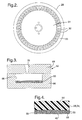
- the impeller 28 is generally planar and circular in shape.
- the impeller 28 has a hub portion 31 attached to the shaft 29 by suitable means (not shown).
- the impeller 28 also has a plurality of blade tips 32 extending radially from the hub portion 31 and disposed circumferentially thereabout.
- the impeller 28 has a peripheral ring portion 33 extending radially from the blade tips 32 to shroud the blade tips 32.
- the impeller 28 is made of a plastic material to be described.
- the pump section 14 also includes an inlet plate 34 disposed axially on one side of the impeller 28 and an outlet plate 36 disposed axially on the other side of the impeller 28.
- the inlet plate 34 and outlet plate 36 are generally planar and circular in shape.
- the inlet plate 34 and outlet plate 36 are enclosed by a housing 38 and fixed thereto.
- the inlet plate 34 and outlet plate 36 have an inlet or first recess 40 and an outlet or second recess 42, respectively, located axially opposite the blade tips 32 adjacent to the peripheral ring portion 33 to form a flow channel 43 for a function to be described.
- the recesses 40 and 42 are annular and allow fuel to flow therethrough from an inlet port (not shown) to an outlet port 45 of the pump section 14.
- the peripheral ring portion 33 of the impeller 28 forms an outside diameter (OD) sealing surface 46 on both axial sides thereof with the inlet plate 34 and outlet plate 36. It should be appreciated that the impeller 28 rotates relative to the inlet plate 34 and outlet plate 36 and the inlet and outlet plates 34 and 36 are stationary.
- the pump section 14 also includes a spacer ring 48 disposed axially between the inlet plate 34 and outlet plate 36 and spaced radially from the impeller 28.
- the spacer ring 48 is fixed to the housing 38 and is stationary relative to the impeller 28.
- the spacer ring 48 is generally planar and circular in shape.
- the spacer ring 48 has an inner diameter 50 that is spaced from the outside diameter of the peripheral portion 33 of the impeller to form an outside diameter (OD) cavity 52 between the inner diameter 50 of the spacer ring 48 and an outside diameter of the peripheral ring portion 33 of the impeller 28.
- the impeller 28, inlet plate 34 and/or outlet plate 36 are made of a plastic compound having an abrasive wear resistance.
- the plastic compound is a plastic base resin material 54 and an abrasion wear resistant filler material 56 ( Figure 4).
- the concentration and size of the filler material 56 is selected such as zirconium oxide with a 40 micron typical particle size.
- the filler material 56 is in a crushed or beaded form.
- the filler material 56 is bounded together with a binder 58 such as a low molecular weight phenolic liquid or powdered resin to form a micro-porous insert 60.
- the binder 58 also produces a good bond between the base resin material 54 and the filler material 56 and combine attributes of impact resistance to prevent chipping and cross-link density to improve tear resistance.
- the low molecular weight of the resin for the binder 58 is ductile and formable at molding temperatures, which allows the insert 60 to comply with the shape of a mold 62 to be described.
- a plastic molding process, injection or compression, is used to make fuel pump parts such as the impeller 28, inlet plate 34 and/or outlet plate 36 with a high content of filler material 56 at the surface and the base resin material 54 throughout the remaining portion.
- the highly filled surface is micro-porous and allows the base resin material 54 to penetrate and fill the voids within the micro-porous insert 60 and establish a bond with particles of the filler material 56.
- the insert 60 has adequate porosity to allow the plastic base resin material 54 to flow through and be of a proper material or coating to form a bond with the base resin material 54.
- the insert 60 may be made of filler material 56 in the form of beads of ZrO2 coated with the binder 58 of low molecular weight phenolic resin.
- the insert 60 could be pressed into a disc of proper geometry to fit a mold cavity of a mold 62 to be described.
- the bead size of the filler material 56, coating material, pressure and temperature is optimized to create the desired porosity of the insert 60. It should be appreciated that small holes could be pressed into the insert 60 to improve material flow through the surface.
- the compound may be modified by increasing the cross-link density to harden the base resin material 54 and improve its tear strength.
- Eight formulations have been developed to investigate the effects of filler material types, degree of cure and impact strength modifiers on abrasion resistance. The results and formulations are shown in Table 1 below.
- compositions of the compound that would improve abrasion resistance and enhance durability of fuel pump parts.
- zirconia is superior to silica or ceramic spheres in abrasion resistance.
- Significant improvements in abrasion resistance are observed when the degree of cure is increased by adding 1% additional Hexa (compare formulation 3 & 4).
- formulation PR-1 and 5 it should be noted that the addition of an impact strength modifier, Paphen PHGF, also improves abrasion resistance, even for a formulation that already has appreciable abrasion resistance. Addition of both curative and impact modifiers lead to much improved abrasion resistance as seen in the case of formulation 6.
- a method, according to the present invention, of introducing wear resistant filler material 56 to only a surface of interest of plastic plates 28,34,36 in the fuel pump 12 is shown.
- the method includes the steps of forming a porous insert 60 of the desired abrasion wear resistant filler material 56 by insert molding a preformed or pilled layer on the surface that the wear resistance is required.
- a mold generally indicated at 62, has a first mold half 64 with a mold cavity 66 and a second mold half 68 adjacent the first mold half 64.
- the second mold half 68 includes an injection gate 70 for injection molding the plastic material.
- the insert 60 is preformed with a high porosity to allow plastic material flow therethrough.
- the method includes the step of inserting the insert 60 into the mold cavity 66.
- the method includes performing the plastic molding process by injecting the base resin material 54 through the injection gate 70 to fill the mold cavity 66 to create a plastic plate 28,34,36 having a high content filler material 56 at the desired wear resistant surface and the base resin material 54 throughout the remaining portion.
- the injection of plastic flow pressure holds the insert 60 against the desired tool steel of the mold 62.
- a finished molded pump part such as the impeller 28 and/or plates 34,36 includes a typical plastic layer of base resin material 54, bonded to a wear resistant insert 60.
- the insert 60 consists of a wear resistant filler material 56 and a low molecular weight phenolic resin 58.
- the insert 60 is of adequate porosity, prior to molding, to allow the plastic to flow through and produce a diffusion zone consisting of a high concentration of wear resistant filler material 56 and plastic base resin material 54. It should also be appreciated that the method applies a desired abrasion wear resistance filler material 56 to the wear interfaces of interest by insert molding a preformed wear resistant insert 60 to the surface of interest.
- an electostatic or plasma spraying of the desired filler material 56 onto the tool steel surface of the mold 62 prior to molding may be used to achieve the same highly filled surface as described above.
- the surface treatment and/or filler material 56 must be compatible with the plastic base resin material 54 to form a bond.
- the density of the spray coating must remain of adequete porosity to allow the plastic base resin material 54 to flow through.
- a two step molding process may be used to achieve the same highly filled surface as described above.
- a first plastic compound of the base resin material 54 is introduced into the mold 62.
- a second plastic compound containing a high concentration of the abrasion wear resistant filler material 56 is introduced into the mold 62 at the desired surface.
- the second plastic compound is conducted while the first plastic compound is uncured. It should be appreciated that this will aid in the bonding between the two components.
Landscapes
- Engineering & Computer Science (AREA)
- Mechanical Engineering (AREA)
- General Engineering & Computer Science (AREA)
- Manufacturing & Machinery (AREA)
- Structures Of Non-Positive Displacement Pumps (AREA)
Abstract
Description
| Formulations, Percent by Weight | ||||||||
| PR-1 | PR-2 | 1 | 2 | 3 | 4 | 5 | 6 | |
| Ingredients (wt.%) | ||||||||
| Phenolic Binder Plenco 12390 | 5 | 5 | 10 | 10 | 10 | 10 | 10 | 10 |
| Zirconium Oxide | 95 | - | 90 | - | - | - | 88 | 87 |
| Novakup 200 Malvern Microcrystalline Silica, Platy, Treated | - | 95 | - | 90 | - | - | - | - |
| Zeospheres G-800 3M Ceramic Spheres | - | - | - | - | 90 | 89 | - | - |
| Paphen PHGF Phenoxy Resin Phenoxy Specialties Co. | - | - | - | - | 0 | - | 2 | 2 |
| Hexa, Plenco Hexamethylene | - | - | - | - | - | 1 | - | 1 |
| Tetraamine,Curing agent | ||||||||
| Degree of Abrasion (g) | 0.404 | 0.365 | 0.293 | 2.328 | 2.275 | 0.463 | 0.219 | 0.046 |
Claims (24)
- A wear resistant fuel pump for a vehicle comprising:a pump section having a flow channel and a rotatable impeller cooperating with said flow channel to pump fuel therethrough;a motor section disposed adjacent said pump section and having a motor to rotate said impeller;an outlet section disposed adjacent said motor section to allow pumped fuel to exit said fuel pump; andsaid pump section including a plurality of plates disposed axially adjacent to and cooperating with the impeller, said impeller and said plates being made of a compound having an abrasion wear resistance on a predetermined surface thereof that improves abrasion wear characteristics therebetween.
- A wear resistant fuel pump as set forth in claim 1 wherein said compound comprises a base resin material and a filler rich material.
- A wear resistant fuel pump as set forth in claim 2 including a binder to bind said filler material together to form a porous insert.
- A wear resistant fuel pump as set forth in claim 3 wherein said binder is a low molecular weight phenolic resin.
- A wear resistant fuel pump as set forth in claim 1 wherein said impeller has a hub portion, a plurality of blades disposed circumferentially along said hub portion, and a peripheral ring portion extending radially from said blades having an axial sealing surface on both sides thereof.
- A wear resistant fuel pump as set forth in claim 2 wherein said filler material is highly concentrated at a sealing surface disposed between said impeller and said inlet plate and between said impeller and said outlet plate.
- A wear resistant fuel pump as set forth in claim 2 wherein said base resin material is made of phenolic resin.
- A wear resistant fuel pump as set forth in claim 2 wherein said filler material has a hardness greater than 65 Rc.
- A wear resistant fuel pump as set forth in claim 2 wherein said filler material is in the form of beads.
- A wear resistant fuel pump as set forth in claim 2 wherein said filler material is an abrasion wear resistant material comprising one of ZrO2, silica, alumina, and ceramic spheres.
- A wear resistant fuel pump as set forth in claim 2 wherein said filler material is zirconium oxide with a 40 micron typical particle size.
- A wear resistant fuel pump for a vehicle comprising:a housing;a pump section disposed in said housing having a flow channel and a rotatable impeller cooperating with said flow channel to pump fuel therethrough;a motor section disposed in said housing adjacent said pump section and having a motor to rotate said impeller;an outlet section disposed in said housing adjacent said motor section to allow pumped fuel to exit said fuel pump; andsaid pump section including an inner plate and an outer plate disposed axially adjacent to and cooperating with the impeller, said impeller and said inner plate and said outer plate being made of a compound having an abrasion wear resistance on a predetermined surface thereof that improves abrasion wear characteristics therebetween.
- A wear resistant fuel pump as set forth in claim 12 wherein said compound comprises a base resin material and a filler rich material.
- A wear resistant fuel pump as set forth in claim 13 including a binder to bind said filler material together to form a porous insert.
- A wear resistant fuel pump as set forth in claim 14 wherein said binder is a low molecular weight phenolic resin.
- A wear resistant fuel pump as set forth in claim 13 wherein said filler material has a hardness greater than 65 Rc.
- A wear resistant fuel pump as set forth in claim 13 wherein said impeller has a hub portion, a plurality of blades disposed circumferentially along said hub portion, and a peripheral ring portion extending radially from said blades having an axial sealing surface on both sides thereof.
- A wear resistant fuel pump as set forth in claim 17 wherein said filler material is highly concentrated at said sealing surface disposed between said impeller and said inlet plate and between said impeller and said outlet plate.
- A wear resistant fuel pump as set forth in claim 13 wherein said base resin material is made of phenolic resin.
- A method of introducing abrasion wear resistant filler material to a predetermined surface of interest of plastic plates in a fuel pump for a vehicle comprising:disposing a filler material against a surface of a mold;molding a plastic material against the filler material; andforming a plastic plate with a layer of base resin material and a layer of filler material at the predetermined surface thereof.
- A method as set forth in claim 20 wherein said step of disposing comprises forming a porous insert of filler material.
- A method as set forth in claim 20 wherein said step of disposing comprises spraying filler material against a surface of the mold.
- A method as set forth in claim 20 wherein said step of disposing comprises injecting a compound of filler material in a cavity of the mold.
- A method as set forth in claim 21 including the step of inserting the porous insert into a cavity of the mold.
Applications Claiming Priority (2)
| Application Number | Priority Date | Filing Date | Title |
|---|---|---|---|
| US692934 | 2000-10-20 | ||
| US09/692,934 US6435810B1 (en) | 2000-10-20 | 2000-10-20 | Wear resistant fuel pump |
Publications (2)
| Publication Number | Publication Date |
|---|---|
| EP1199477A2 true EP1199477A2 (en) | 2002-04-24 |
| EP1199477A3 EP1199477A3 (en) | 2003-10-15 |
Family
ID=24782650
Family Applications (1)
| Application Number | Title | Priority Date | Filing Date |
|---|---|---|---|
| EP01203933A Withdrawn EP1199477A3 (en) | 2000-10-20 | 2001-10-19 | Wear resistant fuel pump |
Country Status (2)
| Country | Link |
|---|---|
| US (1) | US6435810B1 (en) |
| EP (1) | EP1199477A3 (en) |
Cited By (2)
| Publication number | Priority date | Publication date | Assignee | Title |
|---|---|---|---|---|
| EP1286054A1 (en) * | 2001-08-21 | 2003-02-26 | Delphi Technologies, Inc. | Wear resistant fuel pump |
| US6974301B2 (en) | 2002-07-11 | 2005-12-13 | Nikkiso Co., Ltd. | Self priming regenerative pump |
Families Citing this family (13)
| Publication number | Priority date | Publication date | Assignee | Title |
|---|---|---|---|---|
| US6733249B2 (en) | 2001-05-17 | 2004-05-11 | Delphi Technologies, Inc. | Multi-stage internal gear fuel pump |
| US6758656B2 (en) | 2001-05-17 | 2004-07-06 | Delphi Technologies, Inc. | Multi-stage internal gear/turbine fuel pump |
| DE10200791A1 (en) * | 2002-01-11 | 2003-07-24 | Pierburg Gmbh | Side channel pump |
| DE10201405A1 (en) * | 2002-01-15 | 2003-07-24 | Siemens Ag | Pump for pumping fuel has a pump casing with a pumping chamber fitted with inlets and outlets as well as a pumping wheel in the chamber fastened on a drive shaft rotating on bearings in the casing. |
| US6932562B2 (en) * | 2002-06-18 | 2005-08-23 | Ti Group Automotive Systems, L.L.C. | Single stage, dual channel turbine fuel pump |
| US7037066B2 (en) | 2002-06-18 | 2006-05-02 | Ti Group Automotive Systems, L.L.C. | Turbine fuel pump impeller |
| JP4534677B2 (en) * | 2003-10-31 | 2010-09-01 | 株式会社デンソー | Fuel pump |
| JP2005315158A (en) * | 2004-04-28 | 2005-11-10 | Toshiba Corp | Pumps, cooling devices, and electronics |
| ES2343863T3 (en) * | 2005-09-26 | 2010-08-11 | University Of Leeds | ADMINISTRATION OF PHARMACO. |
| DE102010049138A1 (en) * | 2010-10-22 | 2012-04-26 | Ksb Aktiengesellschaft | Device for pump monitoring |
| US9249806B2 (en) | 2011-02-04 | 2016-02-02 | Ti Group Automotive Systems, L.L.C. | Impeller and fluid pump |
| US10184475B2 (en) | 2015-07-20 | 2019-01-22 | Delphi Technologies Ip Limited | Fluid pump with flow impedance member |
| US10584701B2 (en) | 2017-03-13 | 2020-03-10 | Delphi Technologies Ip Limited | Fluid pump with rotating pumping element wear reduction |
Family Cites Families (7)
| Publication number | Priority date | Publication date | Assignee | Title |
|---|---|---|---|---|
| US3876579A (en) * | 1972-03-27 | 1975-04-08 | Rexnord Inc | Composition to be applied to a surface to increase its wear resistance |
| JPH01287242A (en) * | 1988-05-11 | 1989-11-17 | Hitachi Ltd | Surface modified parts and their manufacturing method |
| DE4022467C3 (en) * | 1990-07-14 | 1995-08-31 | Vdo Schindling | Delivery unit, in particular for the delivery of fuel |
| US5409357A (en) * | 1993-12-06 | 1995-04-25 | Ford Motor Company | Impeller for electric automotive fuel pump |
| US5549446A (en) * | 1995-08-30 | 1996-08-27 | Ford Motor Company | In-tank fuel pump for highly viscous fuels |
| DE19634253A1 (en) * | 1995-12-30 | 1997-07-03 | Bosch Gmbh Robert | Unit for delivering fuel |
| US5867900A (en) * | 1997-08-26 | 1999-02-09 | Ecowater Systems, Inc. | Plastic coated valve rotor and a method of manufacturing |
-
2000
- 2000-10-20 US US09/692,934 patent/US6435810B1/en not_active Expired - Fee Related
-
2001
- 2001-10-19 EP EP01203933A patent/EP1199477A3/en not_active Withdrawn
Cited By (3)
| Publication number | Priority date | Publication date | Assignee | Title |
|---|---|---|---|---|
| EP1286054A1 (en) * | 2001-08-21 | 2003-02-26 | Delphi Technologies, Inc. | Wear resistant fuel pump |
| US6623237B2 (en) | 2001-08-21 | 2003-09-23 | Delphi Technologies, Inc. | Wear resistant fuel pump |
| US6974301B2 (en) | 2002-07-11 | 2005-12-13 | Nikkiso Co., Ltd. | Self priming regenerative pump |
Also Published As
| Publication number | Publication date |
|---|---|
| US6435810B1 (en) | 2002-08-20 |
| EP1199477A3 (en) | 2003-10-15 |
Similar Documents
| Publication | Publication Date | Title |
|---|---|---|
| US6435810B1 (en) | Wear resistant fuel pump | |
| US6402460B1 (en) | Abrasion wear resistant fuel pump | |
| CN108240335A (en) | For the injection molding sealing element of compressor | |
| US6454521B1 (en) | Wear resistant fuel pump | |
| EP1953400A1 (en) | Resin retainer and rolling bearing | |
| US11033966B2 (en) | Flow-conducting component | |
| US6623237B2 (en) | Wear resistant fuel pump | |
| CN107250507A (en) | The manufacture method of impeller cover, rotating machinery and impeller cover | |
| WO2017057533A1 (en) | Inscribed gear pump | |
| CN1734113A (en) | Hydrodynamic Bearing Unit | |
| US6737016B2 (en) | Process for manufacturing sintered slide bearing | |
| JPS631030Y2 (en) | ||
| JP7448027B2 (en) | Motor rotor and motor rotor manufacturing method | |
| US20020071758A1 (en) | Impeller for fuel pump | |
| CN110566671A (en) | Mineral skeleton bonded wear-resistant body floating seal pair and preparation method thereof | |
| WO2006117901A1 (en) | Sliding device | |
| CN210600180U (en) | Floating sealing pair of mineral framework cementing wear-resistant body | |
| JP6449977B2 (en) | Method for manufacturing compression bonded magnet with case | |
| JP3476924B2 (en) | Manufacturing method of swash plate type hydraulic rotary machine | |
| CN103370496A (en) | Turbocompressor rotor and method for producing the same | |
| JPH0615867B2 (en) | Scroll compressor | |
| JP2003184779A (en) | Impeller for circumferential pump | |
| WO2015163925A1 (en) | Systems and methods for manufacturing a shrouded impeller | |
| KR102078875B1 (en) | Water pump and method for manufacturing the same | |
| US3572963A (en) | Inlet turning ring seal |
Legal Events
| Date | Code | Title | Description |
|---|---|---|---|
| PUAI | Public reference made under article 153(3) epc to a published international application that has entered the european phase |
Free format text: ORIGINAL CODE: 0009012 |
|
| AK | Designated contracting states |
Kind code of ref document: A2 Designated state(s): AT BE CH CY DE DK ES FI FR GB GR IE IT LI LU MC NL PT SE TR |
|
| AX | Request for extension of the european patent |
Free format text: AL;LT;LV;MK;RO;SI |
|
| PUAL | Search report despatched |
Free format text: ORIGINAL CODE: 0009013 |
|
| AK | Designated contracting states |
Kind code of ref document: A3 Designated state(s): AT BE CH CY DE DK ES FI FR GB GR IE IT LI LU MC NL PT SE TR |
|
| AX | Request for extension of the european patent |
Extension state: AL LT LV MK RO SI |
|
| RIC1 | Information provided on ipc code assigned before grant |
Ipc: 7F 04D 29/02 B Ipc: 7F 04D 29/18 B Ipc: 7F 04D 5/00 A |
|
| 17P | Request for examination filed |
Effective date: 20040415 |
|
| AKX | Designation fees paid |
Designated state(s): DE FR GB |
|
| 17Q | First examination report despatched |
Effective date: 20040706 |
|
| GRAP | Despatch of communication of intention to grant a patent |
Free format text: ORIGINAL CODE: EPIDOSNIGR1 |
|
| GRAS | Grant fee paid |
Free format text: ORIGINAL CODE: EPIDOSNIGR3 |
|
| STAA | Information on the status of an ep patent application or granted ep patent |
Free format text: STATUS: THE APPLICATION IS DEEMED TO BE WITHDRAWN |
|
| 18D | Application deemed to be withdrawn |
Effective date: 20070220 |