EP1198392B1 - Container with stacked sheets and packaging method - Google Patents
Container with stacked sheets and packaging method Download PDFInfo
- Publication number
- EP1198392B1 EP1198392B1 EP99965736A EP99965736A EP1198392B1 EP 1198392 B1 EP1198392 B1 EP 1198392B1 EP 99965736 A EP99965736 A EP 99965736A EP 99965736 A EP99965736 A EP 99965736A EP 1198392 B1 EP1198392 B1 EP 1198392B1
- Authority
- EP
- European Patent Office
- Prior art keywords
- stack
- sheets
- retaining portions
- base portion
- container
- Prior art date
- Legal status (The legal status is an assumption and is not a legal conclusion. Google has not performed a legal analysis and makes no representation as to the accuracy of the status listed.)
- Expired - Lifetime
Links
- 238000004806 packaging method and process Methods 0.000 title claims description 7
- 238000000034 method Methods 0.000 title claims description 5
- 239000000463 material Substances 0.000 claims description 16
- 239000002184 metal Substances 0.000 claims description 10
- 229910052751 metal Inorganic materials 0.000 claims description 10
- 230000003678 scratch resistant effect Effects 0.000 claims description 9
- 238000005452 bending Methods 0.000 claims 1
- 238000000576 coating method Methods 0.000 description 3
- 229910000831 Steel Inorganic materials 0.000 description 2
- 239000011248 coating agent Substances 0.000 description 2
- 230000000717 retained effect Effects 0.000 description 2
- 239000010959 steel Substances 0.000 description 2
- 235000017166 Bambusa arundinacea Nutrition 0.000 description 1
- 235000017491 Bambusa tulda Nutrition 0.000 description 1
- 241001330002 Bambuseae Species 0.000 description 1
- RYGMFSIKBFXOCR-UHFFFAOYSA-N Copper Chemical compound [Cu] RYGMFSIKBFXOCR-UHFFFAOYSA-N 0.000 description 1
- 235000015334 Phyllostachys viridis Nutrition 0.000 description 1
- 239000004743 Polypropylene Substances 0.000 description 1
- 239000004809 Teflon Substances 0.000 description 1
- 229920006362 Teflon® Polymers 0.000 description 1
- 239000003082 abrasive agent Substances 0.000 description 1
- 230000001154 acute effect Effects 0.000 description 1
- 239000011425 bamboo Substances 0.000 description 1
- 229910052802 copper Inorganic materials 0.000 description 1
- 239000010949 copper Substances 0.000 description 1
- 238000005260 corrosion Methods 0.000 description 1
- 230000007797 corrosion Effects 0.000 description 1
- 239000002657 fibrous material Substances 0.000 description 1
- 238000001746 injection moulding Methods 0.000 description 1
- 238000012986 modification Methods 0.000 description 1
- 230000004048 modification Effects 0.000 description 1
- 239000000123 paper Substances 0.000 description 1
- 239000004033 plastic Substances 0.000 description 1
- 229920003023 plastic Polymers 0.000 description 1
- -1 polypropylene Polymers 0.000 description 1
- 229920001155 polypropylene Polymers 0.000 description 1
- 239000007787 solid Substances 0.000 description 1
- 125000000391 vinyl group Chemical group [H]C([*])=C([H])[H] 0.000 description 1
- 229920002554 vinyl polymer Polymers 0.000 description 1
- 238000003466 welding Methods 0.000 description 1
- 239000002023 wood Substances 0.000 description 1
Images


Classifications
-
- B—PERFORMING OPERATIONS; TRANSPORTING
- B65—CONVEYING; PACKING; STORING; HANDLING THIN OR FILAMENTARY MATERIAL
- B65D—CONTAINERS FOR STORAGE OR TRANSPORT OF ARTICLES OR MATERIALS, e.g. BAGS, BARRELS, BOTTLES, BOXES, CANS, CARTONS, CRATES, DRUMS, JARS, TANKS, HOPPERS, FORWARDING CONTAINERS; ACCESSORIES, CLOSURES, OR FITTINGS THEREFOR; PACKAGING ELEMENTS; PACKAGES
- B65D67/00—Kinds or types of packaging elements not otherwise provided for
- B65D67/02—Clips or clamps for holding articles together for convenience of storage or transport
-
- B—PERFORMING OPERATIONS; TRANSPORTING
- B65—CONVEYING; PACKING; STORING; HANDLING THIN OR FILAMENTARY MATERIAL
- B65D—CONTAINERS FOR STORAGE OR TRANSPORT OF ARTICLES OR MATERIALS, e.g. BAGS, BARRELS, BOTTLES, BOXES, CANS, CARTONS, CRATES, DRUMS, JARS, TANKS, HOPPERS, FORWARDING CONTAINERS; ACCESSORIES, CLOSURES, OR FITTINGS THEREFOR; PACKAGING ELEMENTS; PACKAGES
- B65D85/00—Containers, packaging elements or packages, specially adapted for particular articles or materials
- B65D85/62—Containers, packaging elements or packages, specially adapted for particular articles or materials for stacks of articles; for special arrangements of groups of articles
-
- C—CHEMISTRY; METALLURGY
- C09—DYES; PAINTS; POLISHES; NATURAL RESINS; ADHESIVES; COMPOSITIONS NOT OTHERWISE PROVIDED FOR; APPLICATIONS OF MATERIALS NOT OTHERWISE PROVIDED FOR
- C09J—ADHESIVES; NON-MECHANICAL ASPECTS OF ADHESIVE PROCESSES IN GENERAL; ADHESIVE PROCESSES NOT PROVIDED FOR ELSEWHERE; USE OF MATERIALS AS ADHESIVES
- C09J2203/00—Applications of adhesives in processes or use of adhesives in the form of films or foils
- C09J2203/31—Applications of adhesives in processes or use of adhesives in the form of films or foils as a masking tape for painting
-
- C—CHEMISTRY; METALLURGY
- C09—DYES; PAINTS; POLISHES; NATURAL RESINS; ADHESIVES; COMPOSITIONS NOT OTHERWISE PROVIDED FOR; APPLICATIONS OF MATERIALS NOT OTHERWISE PROVIDED FOR
- C09J—ADHESIVES; NON-MECHANICAL ASPECTS OF ADHESIVE PROCESSES IN GENERAL; ADHESIVE PROCESSES NOT PROVIDED FOR ELSEWHERE; USE OF MATERIALS AS ADHESIVES
- C09J2301/00—Additional features of adhesives in the form of films or foils
- C09J2301/10—Additional features of adhesives in the form of films or foils characterized by the structural features of the adhesive tape or sheet
- C09J2301/12—Additional features of adhesives in the form of films or foils characterized by the structural features of the adhesive tape or sheet by the arrangement of layers
- C09J2301/122—Additional features of adhesives in the form of films or foils characterized by the structural features of the adhesive tape or sheet by the arrangement of layers the adhesive layer being present only on one side of the carrier, e.g. single-sided adhesive tape
-
- C—CHEMISTRY; METALLURGY
- C09—DYES; PAINTS; POLISHES; NATURAL RESINS; ADHESIVES; COMPOSITIONS NOT OTHERWISE PROVIDED FOR; APPLICATIONS OF MATERIALS NOT OTHERWISE PROVIDED FOR
- C09J—ADHESIVES; NON-MECHANICAL ASPECTS OF ADHESIVE PROCESSES IN GENERAL; ADHESIVE PROCESSES NOT PROVIDED FOR ELSEWHERE; USE OF MATERIALS AS ADHESIVES
- C09J2301/00—Additional features of adhesives in the form of films or foils
- C09J2301/10—Additional features of adhesives in the form of films or foils characterized by the structural features of the adhesive tape or sheet
- C09J2301/16—Additional features of adhesives in the form of films or foils characterized by the structural features of the adhesive tape or sheet by the structure of the carrier layer
-
- C—CHEMISTRY; METALLURGY
- C09—DYES; PAINTS; POLISHES; NATURAL RESINS; ADHESIVES; COMPOSITIONS NOT OTHERWISE PROVIDED FOR; APPLICATIONS OF MATERIALS NOT OTHERWISE PROVIDED FOR
- C09J—ADHESIVES; NON-MECHANICAL ASPECTS OF ADHESIVE PROCESSES IN GENERAL; ADHESIVE PROCESSES NOT PROVIDED FOR ELSEWHERE; USE OF MATERIALS AS ADHESIVES
- C09J2301/00—Additional features of adhesives in the form of films or foils
- C09J2301/30—Additional features of adhesives in the form of films or foils characterized by the chemical, physicochemical or physical properties of the adhesive or the carrier
- C09J2301/302—Additional features of adhesives in the form of films or foils characterized by the chemical, physicochemical or physical properties of the adhesive or the carrier the adhesive being pressure-sensitive, i.e. tacky at temperatures inferior to 30°C
-
- C—CHEMISTRY; METALLURGY
- C09—DYES; PAINTS; POLISHES; NATURAL RESINS; ADHESIVES; COMPOSITIONS NOT OTHERWISE PROVIDED FOR; APPLICATIONS OF MATERIALS NOT OTHERWISE PROVIDED FOR
- C09J—ADHESIVES; NON-MECHANICAL ASPECTS OF ADHESIVE PROCESSES IN GENERAL; ADHESIVE PROCESSES NOT PROVIDED FOR ELSEWHERE; USE OF MATERIALS AS ADHESIVES
- C09J2423/00—Presence of polyolefin
- C09J2423/006—Presence of polyolefin in the substrate
-
- C—CHEMISTRY; METALLURGY
- C09—DYES; PAINTS; POLISHES; NATURAL RESINS; ADHESIVES; COMPOSITIONS NOT OTHERWISE PROVIDED FOR; APPLICATIONS OF MATERIALS NOT OTHERWISE PROVIDED FOR
- C09J—ADHESIVES; NON-MECHANICAL ASPECTS OF ADHESIVE PROCESSES IN GENERAL; ADHESIVE PROCESSES NOT PROVIDED FOR ELSEWHERE; USE OF MATERIALS AS ADHESIVES
- C09J2423/00—Presence of polyolefin
- C09J2423/04—Presence of homo or copolymers of ethene
- C09J2423/046—Presence of homo or copolymers of ethene in the substrate
-
- C—CHEMISTRY; METALLURGY
- C09—DYES; PAINTS; POLISHES; NATURAL RESINS; ADHESIVES; COMPOSITIONS NOT OTHERWISE PROVIDED FOR; APPLICATIONS OF MATERIALS NOT OTHERWISE PROVIDED FOR
- C09J—ADHESIVES; NON-MECHANICAL ASPECTS OF ADHESIVE PROCESSES IN GENERAL; ADHESIVE PROCESSES NOT PROVIDED FOR ELSEWHERE; USE OF MATERIALS AS ADHESIVES
- C09J2423/00—Presence of polyolefin
- C09J2423/10—Presence of homo or copolymers of propene
- C09J2423/106—Presence of homo or copolymers of propene in the substrate
-
- C—CHEMISTRY; METALLURGY
- C09—DYES; PAINTS; POLISHES; NATURAL RESINS; ADHESIVES; COMPOSITIONS NOT OTHERWISE PROVIDED FOR; APPLICATIONS OF MATERIALS NOT OTHERWISE PROVIDED FOR
- C09J—ADHESIVES; NON-MECHANICAL ASPECTS OF ADHESIVE PROCESSES IN GENERAL; ADHESIVE PROCESSES NOT PROVIDED FOR ELSEWHERE; USE OF MATERIALS AS ADHESIVES
- C09J2427/00—Presence of halogenated polymer
- C09J2427/006—Presence of halogenated polymer in the substrate
Definitions
- the present invention relates to containers for stacks of sheets (e.g., stacks of rectangular or round abrasive covered sheets) in which containers the stack of sheets may be shipped from the manufacturer of the sheets to the consumer, and from which containers that consumer may dispense or withdraw the sheets as they are used.
- sheets e.g., stacks of rectangular or round abrasive covered sheets
- containers have been used for shipping stacks of sheets (e.g., stacks of rectangular or round abrasive covered sheets) from the manufacturer of the sheets to the consumer. Paper or plastic envelopes have been used, as have cardboard boxes. In some instances, the consumer retains the stack of sheets in the container as they are dispensed or withdrawn for use, whereas in other instances the stack of sheets is transferred from the shipping container to a separate dispenser before the sheets are dispensed or withdrawn for use.
- sheets e.g., stacks of rectangular or round abrasive covered sheets
- the object of the present invention is the combination of a stack of sheets and a container, according to claim 1, and a method of packaging the stack of sheets according to claim 8.
- the present invention provides inexpensive containers for stacks of sheets in which the stack of sheets may be shipped from the manufacturer of the sheets to the consumer, and from which that consumer may conveniently dispense or withdraw the sheets as they are used.
- Containers according to the present invention can be easily adapted in size by the manufacturer to accommodate stacks of different size and heights, and afford relatively easy dispensing or withdrawing of sheets by the consumer.
- a container for a stack of sheets which container comprises a base portion adapted to extend transversely across a bottom surface of the stack of sheets and having opposite ends adapted to be positioned at spaced locations along a side surface of the stack of sheets; and a plurality of stiff elongate retaining portions having proximal portions attached to the base portion at its opposite ends with the retaining portions at spaced locations around the side surface of the stack of sheets.
- the retaining portions have central parts adapted to extend along the side surface of the stack of sheets from its bottom surface to its top surface at those spaced locations, and have distal parts adapted to extend above the top surface of the stack of sheets.
- Those retaining portions are bendable to position the distal part in contact with the top surface of the stack of sheets, and the retaining portions will retain the shape to which they are bent sufficiently to retain the stack of sheets in the container.
- the base and retaining portions of the container can be formed of metal wire, with the base portion being formed from first and second lengths of that wire, with each of the lengths of wire being adapted to extend across the bottom surface of the stack of sheets and having opposite ends adapted to be positioned at the spaced locations along the side surface of the stack of sheets; and the retaining portions comprising two generally U-shaped lengths of the wire having opposite ends attached to the first and second lengths of metal wire at the spaced locations.
- Such containers can be custom formed by wire forming equipment at a packaging location to accommodate stacks of sheets of different widths and heights. A sheet bearing information concerning the sheets can be added to the stack, and the stack including the informational sheet can be wrapped in a transparent polymeric material to complete the packaging.
- a coating or layer of scratch resistant material can be placed on the base portion to provide scratch resistant feet for the package, and/or a support bracket can be provided with the container by which its base portion can be supported along a vertical or horizontal surface.
- the base and retaining portions of the container can be portions of a unitary metal stamping
- the base portion can be generally rectangular and can have corners adapted to be positioned at the spaced locations along the side surface of the stack of sheets, and the retaining portions can project from the base portion at its comers.
- the container can be formed of polymeric material (e.g., by injection molding), in which case the retaining portions can be bent by applying heat.
- a container for a stack of sheets can also be provided that has such a base portion adapted to extend transversely across a bottom surface of the stack of sheets and opposite ends adapted to be positioned at spaced locations along a side surface of the stack of sheets; and a plurality of stiff elongate retaining portions having proximal portions attached to the base portion at its opposite ends with the retaining portions at spaced locations around the side surface of the stack of sheets, which retaining portions have central parts adapted to extend along the side surface of the stack of sheets from its bottom surface to its top surface at those spaced locations, and have distal parts generally in the shape of hooks with surfaces positioned to engage the top surface of the stack of sheets to retain the stack of sheets in the container.
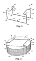
- FIG. 1 there is illustrated a first embodiment of a container for a stack 11 of round sheets or discs, which container is generally designated by the reference numeral 10.
- the container 10 is formed of wire (e.g., 16 or 18 gauge copper plated, corrosion resistant wire of the type used in wire fed electrical welders) and includes two parallel spaced portions 12 of the wire forming a base portion 13 of the container 10, which portions 12 are adapted to extend transversely across a bottom surface 14 of the stack 11 of sheets.
- the base portion 13 has opposite ends defined by the wire portions 12 that are adapted to be positioned at spaced locations along a side surface 17 of the stack 11 of sheets.
- the container 10 also includes a plurality of stiff elongate retaining portions 18 defined by generally U-shaped portions of the wire that have proximal ends 20 attached to the base portion 13 at its opposite ends with the retaining portions 18 at spaced locations around the side surface 17 of the stack 11 of sheets.
- the retaining portions 18 have central parts 22 adapted to extend along the side surface 17 of the stack 11 of sheets from its bottom surface to its top surface at those spaced locations, and have distal parts 26 adapted to extend above the top surface of the stack 11 of sheets.
- the wire forming the retaining portions 18 is bendable by the application of a significant force (i.e., either by a machine or manually) to position the distal parts 26 in contact with the top surface of the stack 11 of sheets and, after being bent, retains a shape to which the retaining portions 18 are bent (i.e., retains its shape until a significant force is again applied to bend it) sufficiently to retain the stack 11 of sheets in the container 10 as is illustrated in Figure 2.
- the container 10 can be custom formed by wire forming equipment at a packaging location to accommodate stacks of sheets of different widths and heights in the form illustrated in Figure 3 with its retaining portions 18 projecting upwardly at right angles to its base portion 13.
- the stack 11 of sheets (including if desired, a sheet forming the top or bottom surface of the stack 11 bearing information concerning the sheets) can be placed in the container 10 and pressed together against the base portion 13.
- the retaining portions 18 can be bent by the wire forming equipment or otherwise to place their distal parts 26 in contact with the top surface of the stack 11 as illustrated in Figure 2. If desired, the stack 11 and container 10 around it can then be wrapped in a transparent polymeric material (not illustrated).
- Figure 4 illustrates a second embodiment of a container 40 according to the present invention that includes all of the portions of the container 10 described above which bear the same numerical references, together with layers 42 (e.g., coatings or tubes) of scratch resistant polymeric or rubber material (e.g., vinyl or Teflon) on or around the portions 12 of the wire forming the base portion 13 to provide a scratch resistant bottom surface for the container 40.
- layers 42 e.g., coatings or tubes
- scratch resistant polymeric or rubber material e.g., vinyl or Teflon
- Figure 5 illustrates a third embodiment of a container 50 according to the present invention which has almost all of the same portions described above with reference to the container 10 (those same portions bearing the same numerical references to which have been added the suffix "a").
- the container 50 only differs from the container 10 in that its base portion 52 is formed by first and second straight portions 54 and 56 of the wire that form the base portion, instead of being parallel, extend across each other to form an X-shaped base portion, and are attached by welding to each other where they cross.
- Figure 6 of the drawing illustrates a fourth embodiment of a container for a stack of sheets generally designated by the reference numeral 60.
- the container 60 is a sheet metal stamping (e.g., 16 or 18 gauge steel having thicknesses of 0.0598 inch (0.15 cm) or 0.0478 inch (0,12cm, respectively) and includes a rectangular base portion 63 adapted to extend transversely across a bottom surface of the stack of sheets, which base portion 63 has corners 66 at opposite ends that are adapted to be positioned at spaced locations along a side surface of the stack of sheets.
- the container 60 also includes a plurality of or four stiff elongate retaining portions 68 that have proximal ends 70 attached to the base portion 63 at its corners 66 with the retaining portions 68 at spaced locations around the side surface of the stack of sheets, having central parts 62 adapted to extend along the side surface of the stack of sheets from its bottom surface to a top surface of the stack of sheets at those spaced locations, and having distal parts 72 adapted to extend above the top surface of the stack of sheets.
- the retaining portions 68 are bendable (e.g., by a machine or manually) to position the distal parts 72 in contact with the top surface of the stack of sheets and, after being bent, retain a shape to which the retaining portions 68 are bent sufficiently (i.e., retains its shape until again bent with significant force) to retain the stack of sheets in the container 60.
- the container 60 could have a layer (not illustrated) of scratch resistant polymeric or rubber material on the outer surface of the base portion 63 to provide a scratch resistant bottom surface for the container 60.
- Figure 7 illustrates a generally rectangular support bracket 74 mounted on a surface 75 (e.g., vertical or horizontal surface 75) by which the base portions of the containers 10, 40, 50, and 60 described above can be supported and retained along that vertical surface 75 to facilitate removing sheets from the containers.
- the bracket 74 has a lower portion 76 attached along the surface 75 by fasteners 77, and is bent to space an upper portion 78 of the bracket 74 away from the surface so that the base portion of one of the containers 10, 40, 50, or 60 can be positioned and retained between that upper portion 78 and the surface 75.
- Figure 8 illustrates a fifth embodiment of a container 80 according to the present invention for a stack 81 of sheets, which container 80 could be stamped from metal (e.g., steel) or molded of a polymeric material (e.g., polypropylene).
- the container 80 includes a circular base portion 83 adapted to extend transversely across a bottom surface of the stack 81 of sheets, which base portion 83 has a periphery adapted to be positioned along a side surface of the stack 81 of sheets.
- the container 80 also includes a plurality of or four stiff elongate retaining portions 88 that have proximal ends 90 attached to the base portion 83 at equally spaced positions around its periphery to position the retaining portions 88 at spaced locations around the side surface of the stack 81 of sheets.
- the retaining portions 88 have central parts 62 adapted to extend along the side surface of the stack of 81 sheets from its bottom surface to a top surface of the stack 81 of sheets at those spaced locations, and having distal parts 96 adapted to extend above the top surface of the stack 81 of sheets.
- the retaining portions 88 are manually bendable (i.e., with the application of heat when made of polymeric material) to position the distal parts 96 in contact with the top surface of the stack 81 of sheets and, after being bent and, if necessary, cooled, retain a shape to which the retaining portions 88 are bent sufficiently (i.e., retains its shape until again heated and manually bent) to retain the stack 81 of sheets in the container 80.
- the retaining portions 88 of the container 80 could be bent to have distal parts 96 in the shape illustrated in Figure 8 before the stack 81 of sheets is placed in the container 80.
- the stack 81 of sheets could then be placed in the container 80 by pressing it downwardly between the retaining portions 88, whereupon the uppermost surfaces 98 of the distal parts 96, which are disposed at an acute angle (e.g., preferably less than 45 degrees) with respect to the side surface of the stack 81 of sheets, will act as cams to resiliently deflect the retaining portions 88 outwardly until the stack 81 of sheets is positioned beneath the distal parts 96.
- the distal parts 96 will then move along the top surface of the stack 81 of sheets to retain it in the container 80. If the retaining portions 88 of the container 80 are so molded, the distal parts 96 could be molded to have solid triangular cross sections.
- any of the containers could have a layer of scratch resistant polymeric or rubber material on the outer surface of their base portion to provide a scratch resistant bottom surface for the container.
- the containers illustrated and described above each have four retaining portions, they, alternatively, could have less (e.g., three) or more (e.g., 5 or 6) retaining portions.
Landscapes
- Engineering & Computer Science (AREA)
- Mechanical Engineering (AREA)
- Packages (AREA)
- Stackable Containers (AREA)
- Buffer Packaging (AREA)
Description
Claims (9)
- A combination comprising:a stack (11) of sheets having a bottom surface (14) defined by a bottom sheet in the stack (11), a side surface (17) defined by edges of sheets in the stack (11), and a top surface defined by an uppermost sheet in the stack (11); anda container (10, 40, 50, 60) comprising:a base portion (13, 52, 63) extending transversely across the bottom surface (14) of the stack (11) of sheets, said base portion (13, 52, 63) having opposite ends positioned at spaced locations along the side surface (17) of the stack (11) of sheets; anda plurality of stiff elongate retaining portions (18, 18a, 68) having proximal ends attached to said base portion (13, 52, 63) at said opposite ends with said retaining portions (18, 18a, 68) at spaced locations around the side surface (17) of the stack (11) of sheets, having central parts extending along the side surface (17) of the stack (11) of sheets from the bottom surface (14) to the top surface of the stack (11) of sheets at said spaced locations, and having distal parts (26, 26a, 72) extending above and in contact with the top surface of the stack (11) of sheets;said combination being characterized in that said retaining portions (18, 18a, 68) are attached in fixed locations with respect to said base portion (13, 52, 63) and are of fixed lengths, that said retaining portions (18, 18a, 68) are non-resiliently bent to position said distal parts (26, 26a, 72) in contact with the top surface of the stack (11) of sheets, and that said retaining portions (18, 18a, 68) retain the shape to which said retaining portions (18, 18a, 68) are bent to retain the stack (11) of sheets in the container (10, 40, 50, 60).
- A combination according to claim 1 wherein said base portion (13, 52) and said retaining portions (18, 18a) are formed of metal wire, said base portion (13, 52) being formed from first and second lengths (12; 54; 56) of said wire, each of said lengths (12; 54, 56) of wire being adapted to extend transversely across the bottom surface (14) of the stack (11) of sheets and having opposite ends adapted to be positioned at said spaced locations along the side surface (17) of the stack (11) of sheets, and said retaining portions (18, 18a) comprising two generally U-shaped lengths of metal wire having opposite ends attached to said first and second lengths (12; 54, 56) of metal wire at said spaced locations.
- A combination according to claim 2 wherein said first and second lengths (54, 56) of wire forming said base portion (52) are straight and cross each other to form an X-shaped base portion (52), said first and second lengths (54, 56) of wire being attached to each other where they cross.
- A combination according to claim 1 further including a layer (42) of scratch resistant polymeric material on said base portion (13, 52).
- A combination according to claim 1 wherein said base portion (63) and said retaining portions (68) are portions of a unitary stamping of sheet metal, said base portion (63) being generally rectangular and having corners (66) positioned at said spaced locations along the side surface (17) of the stack (11) of sheets; and said retaining portions (68) projecting from said base portion (63) at said comers (66).
- A combination according to claim 1 further including an outer wrap of flexible transparent polymeric material around said container and stack of sheets.
- A combination according to claim 1 wherein said base portion and said retaining portions are formed of polymeric material that is bendable upon the application of heat.
- A method for packaging a stack (11) of sheets having a bottom surface (14) defined by a bottom sheet in the stack (11), a side surface (17) defined by edges of sheets in the stack (11), and a top surface defined by an uppermost sheet in the stack (11), said method comprising the steps of:providing a container (10, 40, 50, 60) having abase portion (13, 52, 63) adapted to extend transversely across the bottom surface (14) of the stack (11) of sheets, the base portion (13, 52, 63) having opposite ends adapted to be positioned at spaced locations along the side surface (17) of the stack (11) of sheets; and having a plurality of stiff elongate bendable retaining portions (18, 18a, 68) having proximal ends attached to the base portion (13, 52, 63) at said opposite ends with the retaining portions (18, 18a, 68) at spaced locations around the side surface (17) of the stack (11) of sheets, having central parts adapted to extend along the side surface (17) of the stack (11) of sheets from the bottom surface (14) to the top surface of the stack (11) of sheets at the spaced locations, and having distal parts (26, 26a, 72) adapted to extend above the top surface of the stack (11) of sheets, said retaining portions (18, 18a, 68) being attached in a fixed location with respect to said base portion (13, 52, 63) and being of a fixed length;positioning the stack (11) of sheets against the base portion (13, 52, 63) of the container (10, 40, 50, 60) with the retaining portions (18, 18a, 68) along the side surface (17) of the stack (11) of sheets; andbending the retaining portions (18, 18a, 68) to position the distal parts (26, 26a, 72) of the retaining portions (18, 18a, 68) in contact with the top surface ofthe stack (11) of sheets, the retaining portions (18, 18a, 68) retaining the shape to which said retaining portions (18, 18a, 68) are bent to retain the stack (11) of sheets in the container (10, 40, 50, 60).
- A method for packaging according to claim 8 further including the steps of including a sheet forming the top or bottom surface (14) of the stack (11) bearing information concerning the sheets, and wrapping the stack (11) and container (10, 40, 50, 60) in a transparent polymeric material.
Applications Claiming Priority (3)
| Application Number | Priority Date | Filing Date | Title |
|---|---|---|---|
| US09/357,596 US6321910B1 (en) | 1999-07-20 | 1999-07-20 | Container for stacked sheets |
| US357596 | 1999-07-20 | ||
| PCT/US1999/025192 WO2001005677A1 (en) | 1999-07-20 | 1999-10-27 | Container for stacked sheets |
Publications (2)
| Publication Number | Publication Date |
|---|---|
| EP1198392A1 EP1198392A1 (en) | 2002-04-24 |
| EP1198392B1 true EP1198392B1 (en) | 2004-01-07 |
Family
ID=23406270
Family Applications (1)
| Application Number | Title | Priority Date | Filing Date |
|---|---|---|---|
| EP99965736A Expired - Lifetime EP1198392B1 (en) | 1999-07-20 | 1999-10-27 | Container with stacked sheets and packaging method |
Country Status (6)
| Country | Link |
|---|---|
| US (2) | US6321910B1 (en) |
| EP (1) | EP1198392B1 (en) |
| JP (1) | JP2003505300A (en) |
| AU (1) | AU2143900A (en) |
| DE (1) | DE69914110T2 (en) |
| WO (1) | WO2001005677A1 (en) |
Families Citing this family (9)
| Publication number | Priority date | Publication date | Assignee | Title |
|---|---|---|---|---|
| US7201639B2 (en) * | 2001-04-24 | 2007-04-10 | Hitachi Global Storage Technologies Netherlands B.V. | Powder for disks |
| EP1413527A1 (en) * | 2002-10-21 | 2004-04-28 | Flavius Jobin | Packaging |
| US7718241B2 (en) * | 2003-11-04 | 2010-05-18 | Larry E. Wittmeyer, Jr. | Multi-functional stack of repositionable sheets |
| US20060000731A1 (en) * | 2004-06-30 | 2006-01-05 | Hayne Cheryl A | Abrasive article packaging and method of making same |
| USD781942S1 (en) * | 2011-11-18 | 2017-03-21 | Toyo Tanso Co., Ltd. | Graphite sheet for protecting crucible |
| US20140215967A1 (en) * | 2014-03-20 | 2014-08-07 | Ronald Christopher Zurek | Currency Bundling Aid |
| US9801459B2 (en) * | 2015-11-11 | 2017-10-31 | Michael Joseph Mundy | Dumbbell carrier |
| US10610760B2 (en) * | 2017-03-27 | 2020-04-07 | Daniel A. Nowlan | Weight carrier device |
| USD959758S1 (en) * | 2019-02-25 | 2022-08-02 | Buckeye Innovations LLC | Animal feed block elevator |
Family Cites Families (21)
| Publication number | Priority date | Publication date | Assignee | Title |
|---|---|---|---|---|
| US3318453A (en) * | 1967-05-09 | Reversible file holder | ||
| US563562A (en) | 1896-07-07 | Pastry-rack | ||
| US1211269A (en) | 1915-11-27 | 1917-01-02 | Robert J Abbott | Rack for cooking utensils. |
| US1379379A (en) | 1921-01-04 | 1921-05-24 | Abrahmsen Carl Herman Valfrid | Apparatus for holding plates and the like during washing up and rinsing |
| US1379299A (en) | 1921-01-08 | 1921-05-24 | Frank S Grizzel | Bill-file |
| CH340443A (en) | 1959-03-16 | 1959-08-15 | Zbinden Alfred | Device for stacking and carrying logs |
| US2965016A (en) * | 1959-09-21 | 1960-12-20 | David D Price | Paper rack |
| US3712463A (en) * | 1970-05-15 | 1973-01-23 | U Bestehorn | Indexed packaging and stacking devices |
| FR2247089A5 (en) | 1973-10-09 | 1975-05-02 | Journee Paul | |
| DE7405831U (en) | 1974-02-20 | 1974-05-22 | Faust C Und Sohn | Holder for note staples |
| DE7439832U (en) | 1974-11-29 | 1975-05-28 | Daxberger Siegfried | Device for holding containers together |
| US4298126A (en) * | 1979-08-27 | 1981-11-03 | Griffith-Hope Company | Adjustable holder |
| FI63880C (en) | 1981-09-16 | 1983-09-12 | Keppo Ab Oy | SLIPSKIVEPRODUKT SAMT FOERFARANDE FOER FRAMSTAELLNING DAERAV |
| JPH0637246B2 (en) * | 1986-02-05 | 1994-05-18 | 日本板硝子株式会社 | Flat plate transport storage method for glass plates |
| US4971207A (en) * | 1987-11-20 | 1990-11-20 | Baucom Clarence L | Firewood holders |
| US5050738A (en) * | 1988-04-20 | 1991-09-24 | Mcadams William J | Firewood package |
| US4911308A (en) | 1988-11-07 | 1990-03-27 | Saxvikens Mat Ab | Mobile plate stand |
| US5022316A (en) * | 1989-08-24 | 1991-06-11 | John Hellwig | Newspaper bundler with recyclable straps |
| US5033628A (en) * | 1990-06-21 | 1991-07-23 | Scholes Dean C | Newspaper storage rack |
| MX9101405A (en) | 1990-10-04 | 1992-06-01 | Humbert Bohner | PLACEMENT AND TRANSPORTATION SYSTEM ESPECIALLY FOR GASTRONOMIC PURPOSES |
| US5701999A (en) * | 1996-04-17 | 1997-12-30 | Modern Polymers, Inc. | Product for protectively packaging appliances for storage and shipment |
-
1999
- 1999-07-20 US US09/357,596 patent/US6321910B1/en not_active Expired - Fee Related
- 1999-10-27 JP JP2001511345A patent/JP2003505300A/en active Pending
- 1999-10-27 WO PCT/US1999/025192 patent/WO2001005677A1/en not_active Ceased
- 1999-10-27 DE DE69914110T patent/DE69914110T2/en not_active Expired - Fee Related
- 1999-10-27 AU AU21439/00A patent/AU2143900A/en not_active Abandoned
- 1999-10-27 EP EP99965736A patent/EP1198392B1/en not_active Expired - Lifetime
-
2001
- 2001-06-25 US US09/888,919 patent/US6393805B2/en not_active Expired - Lifetime
Also Published As
| Publication number | Publication date |
|---|---|
| US6321910B1 (en) | 2001-11-27 |
| US6393805B2 (en) | 2002-05-28 |
| AU2143900A (en) | 2001-02-05 |
| DE69914110D1 (en) | 2004-02-12 |
| EP1198392A1 (en) | 2002-04-24 |
| JP2003505300A (en) | 2003-02-12 |
| DE69914110T2 (en) | 2004-06-09 |
| WO2001005677A1 (en) | 2001-01-25 |
| US20010037625A1 (en) | 2001-11-08 |
Similar Documents
| Publication | Publication Date | Title |
|---|---|---|
| CA2185417C (en) | Assembly of packaged reams and method therefor | |
| US11905050B2 (en) | Container carrier applicator and method | |
| US6321910B1 (en) | Container for stacked sheets | |
| US9272832B2 (en) | Pallet cornerboard locator | |
| WO2008003316A1 (en) | Cotton wool pad dispenser | |
| CN1914101A (en) | Kit for providing wound web materials and method for marketing the materials | |
| CA2033393C (en) | Method and article for packaging paper and the like | |
| WO2006091533A1 (en) | Shipping package | |
| US4756488A (en) | Reel core | |
| US6991106B2 (en) | Modular container for holding labels | |
| CA2609267C (en) | Improved shipping and display carton | |
| US6024825A (en) | Method for forming and assembly of folded leaflets | |
| KR19980703101A (en) | Carrier of yogurt bottle | |
| GB2494431A (en) | Box divider | |
| US6199697B1 (en) | Fixing element for an article in a container | |
| JP5313573B2 (en) | Packaging box | |
| US20060249427A1 (en) | Erect package | |
| US20120292427A1 (en) | Combination strapping package and dispenser | |
| US20070194035A1 (en) | Tissue housing and dispensing apparatus and method of use | |
| JP5855833B2 (en) | Neck display | |
| US20130248646A1 (en) | Product Containers with Rolled Goods | |
| JP3088253U (en) | Paper tray and paper tray assembly table | |
| WO1996017791A1 (en) | Improved package assembly for containers | |
| JP5313574B2 (en) | Packaging box | |
| US20220055811A1 (en) | Easy open shrink-wrapped package |
Legal Events
| Date | Code | Title | Description |
|---|---|---|---|
| PUAI | Public reference made under article 153(3) epc to a published international application that has entered the european phase |
Free format text: ORIGINAL CODE: 0009012 |
|
| 17P | Request for examination filed |
Effective date: 20020207 |
|
| AK | Designated contracting states |
Kind code of ref document: A1 Designated state(s): AT BE CH CY DE DK ES FI FR GB GR IE IT LI LU MC NL PT SE |
|
| AX | Request for extension of the european patent |
Free format text: AL;LT;LV;MK;RO;SI |
|
| GRAH | Despatch of communication of intention to grant a patent |
Free format text: ORIGINAL CODE: EPIDOS IGRA |
|
| RTI1 | Title (correction) |
Free format text: CONTAINER WITH STACKED SHEETS AND PACKAGING METHOD |
|
| GRAS | Grant fee paid |
Free format text: ORIGINAL CODE: EPIDOSNIGR3 |
|
| GRAA | (expected) grant |
Free format text: ORIGINAL CODE: 0009210 |
|
| AK | Designated contracting states |
Kind code of ref document: B1 Designated state(s): DE FR GB |
|
| REG | Reference to a national code |
Ref country code: GB Ref legal event code: FG4D |
|
| REG | Reference to a national code |
Ref country code: IE Ref legal event code: FG4D |
|
| REF | Corresponds to: |
Ref document number: 69914110 Country of ref document: DE Date of ref document: 20040212 Kind code of ref document: P |
|
| LTIE | Lt: invalidation of european patent or patent extension |
Effective date: 20040107 |
|
| ET | Fr: translation filed | ||
| PG25 | Lapsed in a contracting state [announced via postgrant information from national office to epo] |
Ref country code: GB Free format text: LAPSE BECAUSE OF NON-PAYMENT OF DUE FEES Effective date: 20041027 |
|
| PLBE | No opposition filed within time limit |
Free format text: ORIGINAL CODE: 0009261 |
|
| STAA | Information on the status of an ep patent application or granted ep patent |
Free format text: STATUS: NO OPPOSITION FILED WITHIN TIME LIMIT |
|
| 26N | No opposition filed |
Effective date: 20041008 |
|
| PG25 | Lapsed in a contracting state [announced via postgrant information from national office to epo] |
Ref country code: DE Free format text: LAPSE BECAUSE OF NON-PAYMENT OF DUE FEES Effective date: 20050503 |
|
| GBPC | Gb: european patent ceased through non-payment of renewal fee |
Effective date: 20041027 |
|
| PG25 | Lapsed in a contracting state [announced via postgrant information from national office to epo] |
Ref country code: FR Free format text: LAPSE BECAUSE OF NON-PAYMENT OF DUE FEES Effective date: 20050630 |
|
| REG | Reference to a national code |
Ref country code: FR Ref legal event code: ST |