EP1197942A2 - Method of driving organic electroluminescence element, apparatus for driving organic electroluminescence element and display using the same - Google Patents
Method of driving organic electroluminescence element, apparatus for driving organic electroluminescence element and display using the same Download PDFInfo
- Publication number
- EP1197942A2 EP1197942A2 EP01308001A EP01308001A EP1197942A2 EP 1197942 A2 EP1197942 A2 EP 1197942A2 EP 01308001 A EP01308001 A EP 01308001A EP 01308001 A EP01308001 A EP 01308001A EP 1197942 A2 EP1197942 A2 EP 1197942A2
- Authority
- EP
- European Patent Office
- Prior art keywords
- organic
- driving
- duty ratio
- organic electroluminescence
- pulse
- Prior art date
- Legal status (The legal status is an assumption and is not a legal conclusion. Google has not performed a legal analysis and makes no representation as to the accuracy of the status listed.)
- Withdrawn
Links
Images





Classifications
-
- G—PHYSICS
- G09—EDUCATION; CRYPTOGRAPHY; DISPLAY; ADVERTISING; SEALS
- G09G—ARRANGEMENTS OR CIRCUITS FOR CONTROL OF INDICATING DEVICES USING STATIC MEANS TO PRESENT VARIABLE INFORMATION
- G09G3/00—Control arrangements or circuits, of interest only in connection with visual indicators other than cathode-ray tubes
- G09G3/20—Control arrangements or circuits, of interest only in connection with visual indicators other than cathode-ray tubes for presentation of an assembly of a number of characters, e.g. a page, by composing the assembly by combination of individual elements arranged in a matrix no fixed position being assigned to or needed to be assigned to the individual characters or partial characters
- G09G3/22—Control arrangements or circuits, of interest only in connection with visual indicators other than cathode-ray tubes for presentation of an assembly of a number of characters, e.g. a page, by composing the assembly by combination of individual elements arranged in a matrix no fixed position being assigned to or needed to be assigned to the individual characters or partial characters using controlled light sources
- G09G3/30—Control arrangements or circuits, of interest only in connection with visual indicators other than cathode-ray tubes for presentation of an assembly of a number of characters, e.g. a page, by composing the assembly by combination of individual elements arranged in a matrix no fixed position being assigned to or needed to be assigned to the individual characters or partial characters using controlled light sources using electroluminescent panels
- G09G3/32—Control arrangements or circuits, of interest only in connection with visual indicators other than cathode-ray tubes for presentation of an assembly of a number of characters, e.g. a page, by composing the assembly by combination of individual elements arranged in a matrix no fixed position being assigned to or needed to be assigned to the individual characters or partial characters using controlled light sources using electroluminescent panels semiconductive, e.g. using light-emitting diodes [LED]
- G09G3/3208—Control arrangements or circuits, of interest only in connection with visual indicators other than cathode-ray tubes for presentation of an assembly of a number of characters, e.g. a page, by composing the assembly by combination of individual elements arranged in a matrix no fixed position being assigned to or needed to be assigned to the individual characters or partial characters using controlled light sources using electroluminescent panels semiconductive, e.g. using light-emitting diodes [LED] organic, e.g. using organic light-emitting diodes [OLED]
-
- G—PHYSICS
- G09—EDUCATION; CRYPTOGRAPHY; DISPLAY; ADVERTISING; SEALS
- G09G—ARRANGEMENTS OR CIRCUITS FOR CONTROL OF INDICATING DEVICES USING STATIC MEANS TO PRESENT VARIABLE INFORMATION
- G09G2300/00—Aspects of the constitution of display devices
- G09G2300/04—Structural and physical details of display devices
- G09G2300/0404—Matrix technologies
- G09G2300/0417—Special arrangements specific to the use of low carrier mobility technology
-
- G—PHYSICS
- G09—EDUCATION; CRYPTOGRAPHY; DISPLAY; ADVERTISING; SEALS
- G09G—ARRANGEMENTS OR CIRCUITS FOR CONTROL OF INDICATING DEVICES USING STATIC MEANS TO PRESENT VARIABLE INFORMATION
- G09G2320/00—Control of display operating conditions
- G09G2320/04—Maintaining the quality of display appearance
- G09G2320/043—Preventing or counteracting the effects of ageing
-
- G—PHYSICS
- G09—EDUCATION; CRYPTOGRAPHY; DISPLAY; ADVERTISING; SEALS
- G09G—ARRANGEMENTS OR CIRCUITS FOR CONTROL OF INDICATING DEVICES USING STATIC MEANS TO PRESENT VARIABLE INFORMATION
- G09G2330/00—Aspects of power supply; Aspects of display protection and defect management
- G09G2330/04—Display protection
-
- H—ELECTRICITY
- H10—SEMICONDUCTOR DEVICES; ELECTRIC SOLID-STATE DEVICES NOT OTHERWISE PROVIDED FOR
- H10K—ORGANIC ELECTRIC SOLID-STATE DEVICES
- H10K59/00—Integrated devices, or assemblies of multiple devices, comprising at least one organic light-emitting element covered by group H10K50/00
- H10K59/10—OLED displays
- H10K59/17—Passive-matrix OLED displays
Definitions
- the present invention relates to a method of driving an organic electroluminescence element, an apparatus for driving an organic electroluminescence element and a display using the same.
- organic EL elements organic electroluminescence elements
- the displays using the organic EL elements have some features. For example, they have an intermediate or high efficiency, are thin and lightweight, and have no viewing angle dependency.
- an organic EL element In an organic EL element, electrons and holes are injected into a luminescent portion, respectively, from an electron injection electrode and a hole injection electrode, the electrons and the holes are recombined at a luminescent center to bring an organic molecule into an excited state, and fluorescence is emittied when the organic molecule is returned from the excited state to a ground state.
- Displays using such organic EL elements have a structure in which a plurality of organic EL elements are arranged in the form of a matrix on a substrate.
- the organic EL elements have the advantage in that they can be driven at low voltages of 5 volts to 20 volts. Further, it is expected that the organic EL elements which emit light in suitable colors can be obtained by selecting fluorescent materials which are luminescent materials, and are also utilized as multi-color or full-color displays.
- a simple matrix system (a passive system), in which a plurality of transparent anodes and a plurality of transparent cathodes which are composed of ITO (Indium Tin Oxide) are arranged so as to cross each other, an organic layer is interposed between the anode and the cathode which cross each other, and carriers are injected into the organic layer by applying a voltage between the two electrodes to emit light.
- ITO Indium Tin Oxide
- the other is an active matrix system, in which a plurality of TFTs (Thin Film Transistors) composed of polycrystalline silicon are formed on a substrate, and an organic layer is formed on a circuit composed of the TFTs, to turn on and off each of organic EL elements serving as pixels by turning the corresponding TFT on and off.
- a capacitor is connected to each of the TFTs.
- the organic EL element In the simple matrix system, only when a voltage is applied between the electrodes in each of the organic EL elements, the organic EL element is turned on. In a display having a QVGA specification having a resolution of 320 dots in width by 240 dots in length, for example, therefore, even when pixels on one line are simultaneously turned on, one of the pixels is driven at a duty ratio of 1 : 240 when one frame is displayed.
- the TFT corresponding to the one pixel can hold an on state for a long time by charges stored in the capacitor.
- each of the organic EL elements is turned on in a state almost close to DC driving.
- each of the organic EL elements must instantaneously emit light in brightness which is 240 times that in the active matrix system. That is, in the simple matrix system, a current which is approximately 240 times that in the active matrix system must be instantaneously caused to flow through each of the organic EL elements.
- An object of the present invention is to provide a method of and an apparatus for driving an organic electroluminescence element in which long life can be attained in pulse driving at a low duty ratio, and a display using the same.
- a method of driving an organic electroluminescence element including an organic material layer comprises the step of applying a pulse voltage having a duty ratio of not more than 10 % between electrodes in the organic electroluminescence element, setting an average drive current flowing through the organic electroluminescence element to not more than 3 mA/cm 2 , and setting an average drive voltage applied between the electrodes in the organic electroluminescence element to not more than 4 volts.
- duty ratio is defined as the ratio of the duration of a high level of voltage to one period of a pulse voltage in percent.
- the driving method when the pulse voltage is applied between the electrodes in the organic electroluminescence element, the current flows through the organic electroluminescence element, so that the organic electroluminescence element intermittently emits light.
- the organic electroluminescence element is pulse-driven under driving conditions , that is , a duty ratio of not more than 10 %, an average drive current of not more than 3 mA/cm 2 , and an average drive voltage of not more than 4 volts, thereby attaining long life of the organic electroluminescence element in the pulse driving at a low duty ratio.
- the average drive voltage is not more than 1 volt. Consequently, the life of the organic electroluminescence element is further improved.
- the organic material layer includes an aluminum quinolinol complex. In this case, the life of the organic electroluminescence element is improved by the above-mentioned driving conditions.
- a driving apparatus for driving an organic electroluminescence element including an organic material layer comprises a pulse voltage application circuit for applying a pulse voltage having a duty ratio of not more than 10 % between electrodes in the organic electroluminescence element, an average drive current flowing through the organic electroluminescence element being set to not more than 3 mA/cm 2 , and an average drive voltage applied between the electrodes in the organic electroluminescence element being set to not more than 4 volts.
- the organic electroluminescence element is pulse-driven under driving conditions, that is, a duty ratio of not more than 10 %, an average drive current of not more than 3 mA/cm 2 , and an average drive voltage of not more than 4 volts, thereby attaining long life of the organic electroluminescence element in the pulse driving at a low duty ratio.
- the average drive voltage is set to not more than 1 volt. Consequently, the life of the organic electroluminescence element is further improved.
- the organic electroluminescence element comprises an organic material layer containing an aluminum quinolinol complex. In this case, the life of the organic electroluminescence element is improved by the above-mentioned driving conditions.
- a display according to still another aspect of the present invention comprises one or a plurality of organic electroluminescence elements including an organic material layer, and a driving device for applying a pulse voltage having a duty ratio of not more than 10 % between electrodes in each of the organic electroluminescence elements, an average drive current flowing through each of the organic electroluminescence elements being set to not more than 3 mA/cm 2 , and an average drive voltage applied between the electrodes in each of the organic electroluminescence elements being set to not more than 4 volts.
- each of the organic electroluminescence elements is pulse-driven under driving conditions, that is, a duty ratio of not more than 10 %, an average drive current of not more than 3 mA/cm 2 , and an average drive voltage of not more than 4 volts, thereby attaining long life of the organic electroluminescence element in the pulse driving at a low duty ratio.
- the driving device is a driving device of a simple matrix system.
- the driving device is a driving device of a simple matrix system.
- the driving device even when each of the organic electroluminescence elements is pulse-driven at a low duty ratio, long life of the organic electroluminescence element is attained. Accordingly, a high definition display can be realized in a simple matrix system.
- the average drive voltage is not more than 1 volt. Consequently, the life of the organic electroluminescence element is further improved.
- the organic material layer contains an aluminum quinolinol complex. In this case, the life of the organic electroluminescence element is improved by the above-mentioned driving conditions.
- Fig. 1 is a schematic view showing an example of the structure of an organic electroluminescence element (hereinafter referred to as an organic EL element) and a pulse voltage application circuit.
- an organic electroluminescence element hereinafter referred to as an organic EL element
- a pulse voltage application circuit hereinafter referred to as an organic EL element
- an anode (a hole injection electrode) 2 composed of a transparent conductive film is formed on a glass substrate 1.
- a hole injection layer 3 composed of an organic material
- a hole transport layer 4 composed of an organic material
- a luminescent layer 5 composed of an organic material are formed in this order on the anode 2.
- a cathode (an electron injection electrode) 6 is formed on the luminescent layer 5.
- the structure of the organic EL element 20 is not limited to the structure shown in Fig. 1. Various structures can be used. For example, a luminescent layer composed of an organic material may be provided in place of the hole transport layer 4, and an electron transport layer composed of an organic material may be provided in place of the luminescent layer 5.
- a pulse voltage application circuit 10 is connected between the anode 2 and the cathode 6 in the organic EL element 20.
- the pulse voltage application circuit 10 applies a pulse voltage to the organic EL element 20, so that the luminescent layer 5 in the organic EL element 20 emits light, and light 100 is emitted form the reverse surface of the glass substrate 1.
- the pulse voltage application circuit 10 applies a pulse voltage having a duty ratio of not more than 10 % to the organic EL element 20.
- driving conditions are set such that an average drive current flowing through the organic EL element 20 (an average injection current density) is not more than 3 mA/cm 2 , and an average drive voltage applied to the organic EL element 20 is not more than 4 volts. Consequently, long life of the organic EL element 20 is attained in pulse driving at a low duty ratio, as apparent from the following examples.
- an anode 2 composed of ITO which is a transparent conductive film was formed on a glass substrate 1
- a hole injection layer 3 having a thickness of 500 ⁇ composed of 2-TNATA (4, 4', 4" - tris (2-naphthylphenylamino) triphenyl - amine) having a molecular structure of a chemical formula (1)
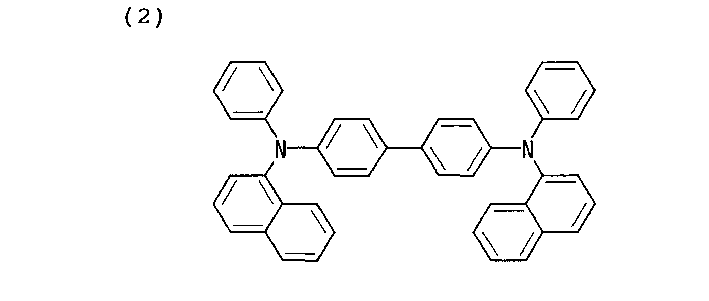
- a hole transport layer 4 having a thickness of 20 ⁇ composed of ⁇ - NPB ( ⁇ - N,N' - Di(naphthalene - 1 - y1) - N,N'-Di(phenyl - benzidine)) having a molecular structure of a chemical formula (2)
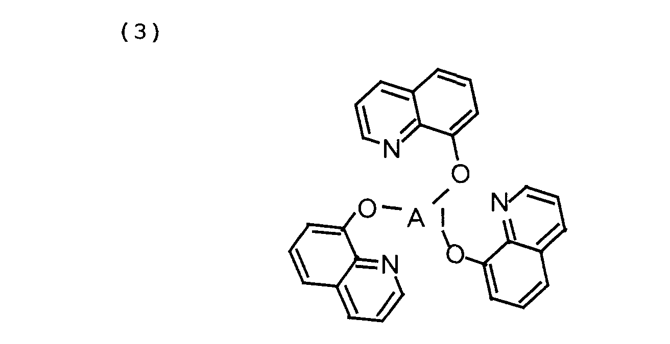
- a luminescent layer 5 having a thickness of 400 ⁇ composed of Alq 3 (Tris (8 - hydroxy-quinolinate) aluminum or Tris (8 - quinolinolato) aluminum) which is an aluminum chelate complex having a molecular structure of a chemical formula (3) were stacked on the
- a predetermined voltage was continuously applied to the organic EL element.
- a pulse voltage having a duty ratio of 50 %, a pulse voltage having a duty ratio of 10 %, and a pulse voltage having a duty ratio of 1 % were applied to the organic EL element.
- the frequency of the pulse voltage was set to 60 Hz.
- a voltage was applied to the organic EL element during a period which is 50 % of one period, to cause the organic EL element to emit light, and no voltage was applied to the organic EL element during a period which is the remaining 50 %, not to cause the organic EL element to emit light.
- the pulse driving at a duty ratio of 50 %, the pulse driving at a duty ratio of 10 %, and the pulse driving at a duty ratio of 1 % were adjusted such that the initial average luminance would be 100 cd/m 2 . Further, the continuous luminescence experiments were conducted by constant voltage driving for keeping an average drive voltage constant.
- the peak value of the drive voltage was 7.45 volts in the DC driving, 8.5 volts in the pulse driving at a duty ratio of 50 %, 10.5 V in the pulse driving at a duty ratio of 10 %, and 15.65 volts in the pulse driving at a duty ratio of 1 %.
- the average drive voltage was 7.45 volts in the DC driving, 4. 25 volts in the pulse driving at a duty ratio of 50 %, 1.05 volts in the pulse driving at a duty ratio of 10 %, and 0.1565 volts in the pulse driving at a duty ratio of 1 %.
- the average drive voltage differs depending on the duty ratio.
- the initial value of an average drive current was approximately equal without depending on the duty ratio by the linear relationship between the luminance and the current.
- the initial value of the average drive current (average injection current density) was approximately 3 mA/cm 2 .
- the average drive current is reduced with an elapse of time.
- Fig. 2 is a diagram showing the results of measurement of the duty ratio dependency of the life of the organic EL element in the example 1.
- the horizontal axis represents time
- the vertical axis represents relative luminance in a case where the initial average luminance is set to one.
- the 70 % life was approximately 2 hours in the DC driving, while being lengthened to not less than 20 hours in the pulse driving at a duty ratio of 50 %. Further, the 70 % life was improved to approximately 60 hours in the pulse driving at a duty ratio of 10 % and the pulse driving at a duty ratio of 1 %.
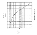
- Fig. 3 is a diagram showing the relationship between an average drive voltage and life.
- the horizontal axis shown in Fig. 3 represents the average drive voltage, and the vertical axis represents the 70 % life.
- the 70 % life was approximately 1.5 hours when the average drive voltage was 7.45 volts, while being lengthened to approximately 25 hours when the average drive voltage was 4.25 volts.
- the 70 % life was improved to approximately 55 hours when the average drive voltage was 1.05 volts, and was improved to approximately 60 hours when the average drive voltage was 1565 volts. From the results, it is found that the effect of preventing the initial luminance from being reduced is increased when the average drive voltage is not more than approximately 4 volts, and is further increased when the average drive voltage is not more than approximately 1 volt.
- an organic EL element having the same element structure as that in the example 1 was fabricated, a drive voltage was applied to the organic EL element by a DC driving system, a pulse driving system of a duty ratio of 50 %, a pulse driving system of a duty ratio of 10 %, and a pulse driving system of a duty ratio of 1 %, and continuous luminescence experiments were respectively conducted at room temperature under driving conditions, that is, an initial average luminance of 1000 cd/m 2 , to examine the amount of luminance reduced with an elapse of time.
- the initial value of an average drive current was approximately 27 mA/cm 2 .
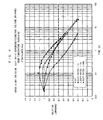
- Fig. 4 is a diagram showing the results of measurement of the duty ratio dependency of the life of the organic EL element in the example 2.
- the horizontal axis represents time
- the vertical axis represents relative luminance in a case where the initial average luminance is set to one.
- the 70 % life was approximately 0.32 hours in DC driving, while being lengthened to 2.6 hours in pulse driving at a duty ratio of 50 %.
- the 70 % life was approximately two hours in both pulse driving at a duty ratio of 10 % and pulse driving at a duty ratio of 1 %, which was shorter than that in the pulse driving at a duty ratio of 50 %.
- a luminescent layer 5 obtained by doping methyl quinacridone into Alq 3 was used.
- the structure of the other portions in the organic EL element in the example 3 is the same as the structure of the organic EL element in the example 1.
- methyl quinacridone was doped into Alq 3 in the luminescent layer 5, thereby making it possible to obtain an organic EL element emitting green light at higher efficiency, as compared with that in a case where a luminescent layer 5 composed of only Alq 3 is used.
- a drive voltage was applied to the organic EL element by a DC driving system, a pulse driving system of a duty ratio of 50 %, and a pulse driving system of a duty ratio of 10 %, and continuous luminescence experiments were respectively conducted at room temperature under driving conditions, that is, an initial average luminance of 500 cd/m 2 , to examine the amount of luminance reduced with an elapse of time.
- the frequency of a pulse voltage was set to 60 Hz. In this case, the initial value of an average drive current was approximately 10 mA/cm 2 .
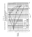
- Fig. 5 is a diagram showing the results of measurement of the duty ratio dependency of the life of the organic EL element in the example 3.
- the horizontal axis represents time
- the vertical axis represents relative luminance in a case where the initial average luminance is set to one.
- the 70 % life was approximately 1.2 hours in DC driving, while being lengthened to approximately 9 hours in pulse driving at a duty ratio of 50 % and approximately 10 hours in pulse driving at a duty ratio of 10 %.
- a luminescent layer having a thickness of 200 ⁇ obtained by doping Rubrene having a molecular structure of a chemical formula (4) into à-NPB was formed on a hole injection layer 3 having a thickness of 500 ⁇ composed of 2-TNATA, an electron transport layer having a thickness of 400 ⁇ composed of Alq 3 was formed on the luminescent layer, and a cathode 6 was formed on the electron transport layer.
- the organic EL element can emit yellow light at high efficiency.
- a drive voltage was applied to the organic EL element by a DC driving system and a pulse driving system, and continuous luminescence experiments were conducted at room temperature, to examine the amount of luminance reduced with an elapse of time.
- a predetermined voltage was continuously applied to the organic EL element.
- a pulse voltage having a duty ratio of 50 %, a pulse voltage having a duty ratio of 10 %, and a pulse voltage having a duty ratio of 1 % were applied to the organic EL element.
- the frequency of the pulse voltage was set to 60 Hz.
- any of DC driving pulse driving at a duty ratio of 50 %, pulse driving at a duty ratio of 10 %, and pulse driving at a duty ratio of 1 %
- the driving conditions were adjusted such that the initial average luminance would be 100 cd/m 2 .
- the continuous luminescence experiments were conducted by constant voltage driving for keeping an average drive voltage constant. Under the driving conditions, the initial value of an average drive current was approximately 1.7 mA/cm 2 .
- Fig. 6 is a diagram showing the results of measurement of the duty ratio dependency of the life of the organic EL element in the example 4.
- the horizontal axis represents time
- the vertical axis represents relative luminance in a case where the initial average luminance is set to one.
- the 70 % life was approximately one hour in the DC driving and approximately 65 hours in the pulse driving at a duty ratio of 50 %, while being significantly improved to 200 hours in the pulse driving at a duty ratio of 10 % and 300 hours in the pulse driving at a duty ratio of 1.
- a luminescent layer 5 obtained by doping DCJTB having a molecular structure of a chemical formula (5) into Alq 3 as a dopant for red light emission as well as doping Rubrene as a luminescence assist dopant was used. That is, the organic EL element has a stacked structure comprising a hole injection layer 3 having a thickness of 500 ⁇ composed of 2-TNATA, a hole transport layer 4 having a thickness of 150 ⁇ composed of á-NPB, and a luminescent layer 5 having a thickness of 400 ⁇ composed of Alq 3 , DCJTB and Rubrene.
- the organic EL element can emit red light. However, it is lower in luminous efficiency, as compared with those in the organic EL elements emitting green light in the examples 1 to 3 and the organic EL element emitting yellow light in the example 4.
- a drive voltage was applied to the organic EL element by a DC driving system and a pulse driving system, and continuous luminescence experiments were conducted at room temperature, to examine the amount of luminance reduced with an elapse of time.
- a predetermined voltage was continuously applied to the organic EL element.
- a pulse voltage having a duty ratio of 50 % and a pulse voltage having a duty ratio of 10 % were applied to the organic EL element.
- the frequency of the pulse voltage was set to 60 Hz.
- the driving conditions were adjusted such that the initial average luminance would be 75 cd/m 2 .
- the continuous luminescence experiments were conducted by constant voltage driving for keeping an average drive voltage constant. Under the above-mentioned driving conditions, the initial value of an average drive current was approximately 15.6 mA/cm 2 .
- Fig. 7 is a diagram showing the results of measurement of the duty ratio dependency of the life of the organic EL element in the example 5.
- the horizontal axis represents time
- the vertical axis represents relative luminance in a case where the initial average luminance is set to one.
- the 70 % life was approximately 7 hours in the DC driving, while being improved to approximately 63 hours in the pulse driving at a duty ratio of 50 % and the pulse driving at a duty ratio of 10 %.
- the results of experiments under various conditions were further added to the results of the continuous luminescence experiments in the examples 1 to 5, to examine the relationship between the average drive current and the life.
- the added results of the experiments were results in a case where the initial average luminance was set to 50 cd/m 2 in the organic EL element, emitting green light, comprising a luminescent layer composed of Alq 3 , a case where the initial average luminance was set to 10 cd/m 2 in the organic EL element, emitting red light, comprising a luminescent layer obtained by doping DCJTB and Rubrene into Alq 3 , and a case where the initial average luminance was set to 2000 cd/m 2 in the organic EL element, emitting yellow light, comprising a luminescent layer obtained by doping Rubrene into ⁇ -NPB.
- Fig. 8 is a diagram showing the relationship between the initial value of the average drive voltage and the life.
- the horizontal axis represents the initial value of the average drive current
- the vertical axis represents the ratio of the 70 % life in the pulse driving at a duty ratio of 10 % to the 70 % life in the DC driving as the improvement rate of the life.
- the improvement rate of the life by the pulse driving at a duty ratio of 10 % is low when the initial value of the average drive current is more than 3 mA/cm 2 irrespective of the difference in the luminescent color and the element structure, while being significantly increased when the initial value of the average drive current is not more than 3 mA/cm 2 .
- the maximum effect of attaining long life is obtained by driving the organic EL element under driving conditions, that is, a duty ratio of not more than 10 %, an average drive current of not more than 3 mA/cm 2 , and an average drive voltage of not more than 4 volts in consideration of the fact that the same effect of improving life can be also obtained, if the duty ratio of the pulse voltage is not more than 10 %, in cases where the duty ratio of the pulse voltage is 1 % and is 0.2 %.
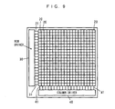
- Fig. 9 is a block diagram showing an example of the configuration of a display of a simple matrix system (a passive system) using the driving device according to the present invention.
- a plurality of organic EL elements having the structure shown in Fig. 1 are arranged in the form of a matrix of n rows and m columns on a common substrate, where n and m are arbitrary integers.
- Anodes 2 (see Fig. 1) of a plurality of organic EL elements 20 forming each row are connected to a driving signal line 31.
- a plurality of driving signal lines 31 corresponding to a plurality of rows are connected to a row driver 30.
- Driving signals are respectively applied to the plurality of driving signal lines 31 by the row driver 30.
- Cathodes 6 (see Fig. 1) of a plurality of organic EL elements 20 forming each column are connected to a column selection signal line 41.
- a plurality of column selection signal lines 41 corresponding to a plurality of columns are connected to a column driver 40.
- Column selection signals are successively applied to the plurality of column selection signal lines 41 by the column driver 40.
- the driving signal applied to the driving signal line 31 by the row driver and the column selection signal applied to the column signal selection line 41 by the column driver 40 are set such that a pulse voltage having a duty ratio of not more than 10 % is applied to the organic EL element 20 which should emit light, and no pulse voltage is applied to the organic EL element which does not emit light.
- an average drive current flowing through the organic EL element 20 which should emit light is set to not more than 3 mA/cm 2 , and an average drive voltage applied to the organic EL element 20 was set to not more than 4 volts. Consequently, a high definition display of a simple matrix system is realized.
Landscapes
- Engineering & Computer Science (AREA)
- Physics & Mathematics (AREA)
- Computer Hardware Design (AREA)
- General Physics & Mathematics (AREA)
- Theoretical Computer Science (AREA)
- Electroluminescent Light Sources (AREA)
- Control Of Indicators Other Than Cathode Ray Tubes (AREA)
- Control Of El Displays (AREA)
Abstract
Description
- The present invention relates to a method of driving an organic electroluminescence element, an apparatus for driving an organic electroluminescence element and a display using the same.
- In recent years, the needs for flat panel displays whose power consumption is lower than that of CRTs (Cathode-Ray Tubes) which have been generally employed have increased as information equipment is diversified. As one type of the flat panel displays, displays using organic electroluminescence elements (hereinafter referred to as organic EL elements) have been actively studied and developed. The displays using the organic EL elements have some features. For example, they have an intermediate or high efficiency, are thin and lightweight, and have no viewing angle dependency.
- In an organic EL element, electrons and holes are injected into a luminescent portion, respectively, from an electron injection electrode and a hole injection electrode, the electrons and the holes are recombined at a luminescent center to bring an organic molecule into an excited state, and fluorescence is emittied when the organic molecule is returned from the excited state to a ground state. Displays using such organic EL elements have a structure in which a plurality of organic EL elements are arranged in the form of a matrix on a substrate.
- The organic EL elements have the advantage in that they can be driven at low voltages of 5 volts to 20 volts. Further, it is expected that the organic EL elements which emit light in suitable colors can be obtained by selecting fluorescent materials which are luminescent materials, and are also utilized as multi-color or full-color displays.
- In order to apply the organic EL elements to high definition displays, two systems have been examined. One of them is a simple matrix system (a passive system), in which a plurality of transparent anodes and a plurality of transparent cathodes which are composed of ITO (Indium Tin Oxide) are arranged so as to cross each other, an organic layer is interposed between the anode and the cathode which cross each other, and carriers are injected into the organic layer by applying a voltage between the two electrodes to emit light. A display constructed by such a simple matrix system is also reported in 9th International Workshop on Inorganic and Organic Electroluminescence Sep.14-18, 1998, Oregon : Extended Abstracts pp.137-140.
- The other is an active matrix system, in which a plurality of TFTs (Thin Film Transistors) composed of polycrystalline silicon are formed on a substrate, and an organic layer is formed on a circuit composed of the TFTs, to turn on and off each of organic EL elements serving as pixels by turning the corresponding TFT on and off. A capacitor is connected to each of the TFTs.
- In the simple matrix system, only when a voltage is applied between the electrodes in each of the organic EL elements, the organic EL element is turned on. In a display having a QVGA specification having a resolution of 320 dots in width by 240 dots in length, for example, therefore, even when pixels on one line are simultaneously turned on, one of the pixels is driven at a duty ratio of 1 : 240 when one frame is displayed.
- On the other hand, in the active matrix system, the TFT corresponding to the one pixel can hold an on state for a long time by charges stored in the capacitor. When one frame is displayed, therefore, each of the organic EL elements is turned on in a state almost close to DC driving.
- In order to maintain the same brightness, therefore, in the simple matrix system, each of the organic EL elements must instantaneously emit light in brightness which is 240 times that in the active matrix system. That is, in the simple matrix system, a current which is approximately 240 times that in the active matrix system must be instantaneously caused to flow through each of the organic EL elements.
- It has been recognition common among researchers in the technical field to cause a large current to instantaneously flow through an organic EL element by pulse driving at a low duty ratio is a factor which reduces the lives of a luminescent material and the organic EL element, as described on page 58 of "Nikkei Electronics 2000. 3. 13. (no. 765)", for example. That is, it has been considered that in pulse driving at a low duty ratio, the peak value of a drive current must be increased in order to obtain predetermined average luminance, imposing a burden on the element so that the life of the element is reduced.
- It is recognized among those skilled in the art that the life of the organic EL element is thus reduced when the organic EL element is pulse-driven at a low duty ratio. Therefore, it has been considered that a high definition display is difficult to construct in a simple matrix system.
- An object of the present invention is to provide a method of and an apparatus for driving an organic electroluminescence element in which long life can be attained in pulse driving at a low duty ratio, and a display using the same.
- It has been recognized among those skilled in the art that it is not desirable to pulse-drive an organic electroluminescence element at a low duty ratio because its life is reduced, as described above. However, the inventors of the present application have obtained the knowledge that the above-mentioned recognition does not necessarily hold, and the life of the organic electroluminescence element is improved by conversely pulse driving at a low duty ratio under particular conditions as a result of repeating zealous experiments and examination with respect to the relationship between the duty ratio of a pulse voltage and the life of the element. The following invention has been contrived on the basis of the knowledge.
- A method of driving an organic electroluminescence element including an organic material layer according to an aspect of the present invention comprises the step of applying a pulse voltage having a duty ratio of not more than 10 % between electrodes in the organic electroluminescence element, setting an average drive current flowing through the organic electroluminescence element to not more than 3 mA/cm2, and setting an average drive voltage applied between the electrodes in the organic electroluminescence element to not more than 4 volts.
- Here, "duty ratio" is defined as the ratio of the duration of a high level of voltage to one period of a pulse voltage in percent.
- In the driving method according to the present invention, when the pulse voltage is applied between the electrodes in the organic electroluminescence element, the current flows through the organic electroluminescence element, so that the organic electroluminescence element intermittently emits light.
- In this case, the organic electroluminescence element is pulse-driven under driving conditions , that is , a duty ratio of not more than 10 %, an average drive current of not more than 3 mA/cm2, and an average drive voltage of not more than 4 volts, thereby attaining long life of the organic electroluminescence element in the pulse driving at a low duty ratio.
- It is preferable that the average drive voltage is not more than 1 volt. Consequently, the life of the organic electroluminescence element is further improved.
- It is preferable that the organic material layer includes an aluminum quinolinol complex. In this case, the life of the organic electroluminescence element is improved by the above-mentioned driving conditions.
- A driving apparatus for driving an organic electroluminescence element including an organic material layer according to another aspect of the present invention comprises a pulse voltage application circuit for applying a pulse voltage having a duty ratio of not more than 10 % between electrodes in the organic electroluminescence element, an average drive current flowing through the organic electroluminescence element being set to not more than 3 mA/cm2, and an average drive voltage applied between the electrodes in the organic electroluminescence element being set to not more than 4 volts.
- In the driving apparatus according to the present invention, the organic electroluminescence element is pulse-driven under driving conditions, that is, a duty ratio of not more than 10 %, an average drive current of not more than 3 mA/cm2, and an average drive voltage of not more than 4 volts, thereby attaining long life of the organic electroluminescence element in the pulse driving at a low duty ratio.
- It is preferable that the average drive voltage is set to not more than 1 volt. Consequently, the life of the organic electroluminescence element is further improved.
- It is preferable that the organic electroluminescence element comprises an organic material layer containing an aluminum quinolinol complex. In this case, the life of the organic electroluminescence element is improved by the above-mentioned driving conditions.
- A display according to still another aspect of the present invention comprises one or a plurality of organic electroluminescence elements including an organic material layer, and a driving device for applying a pulse voltage having a duty ratio of not more than 10 % between electrodes in each of the organic electroluminescence elements, an average drive current flowing through each of the organic electroluminescence elements being set to not more than 3 mA/cm2, and an average drive voltage applied between the electrodes in each of the organic electroluminescence elements being set to not more than 4 volts.
- In the display according to the present invention, each of the organic electroluminescence elements is pulse-driven under driving conditions, that is, a duty ratio of not more than 10 %, an average drive current of not more than 3 mA/cm2, and an average drive voltage of not more than 4 volts, thereby attaining long life of the organic electroluminescence element in the pulse driving at a low duty ratio.
- Particularly, it is preferable that the driving device is a driving device of a simple matrix system. In this case, even when each of the organic electroluminescence elements is pulse-driven at a low duty ratio, long life of the organic electroluminescence element is attained. Accordingly, a high definition display can be realized in a simple matrix system.
- It is preferable that the average drive voltage is not more than 1 volt. Consequently, the life of the organic electroluminescence element is further improved.
- It is preferable that the organic material layer contains an aluminum quinolinol complex. In this case, the life of the organic electroluminescence element is improved by the above-mentioned driving conditions.
- The foregoing and other objects, features, aspects and advantages of the present invention will become more apparent from the following detailed description of the present invention when taken in conjunction with the accompanying drawings.
-
- Fig. 1 is a schematic view showing an example of the structure of an organic EL element and a pulse voltage application circuit;
- Fig. 2 is a diagram showing the results of measurement
of the duty ratio dependency of the life of an organic EL element
in an
embodiment 1; - Fig. 3 is a diagram showing the relationship between an average drive voltage and life;
- Fig. 4 is a diagram showing the results of measurement
of the duty ratio dependency of the life of an organic EL element
in an
embodiment 2; - Fig. 5 is a diagram showing the results of measurement
of the duty ratio dependency of the life of an organic EL element
in an
embodiment 3; - Fig. 6 is a diagram showing the results of measurement
of the duty ratio dependency of the life of an organic EL element
in an
embodiment 4; - Fig. 7 is a diagram showing the results of measurement
of the duty ratio dependency of the life of an organic EL element
in an
embodiment 5; - Fig. 8 is a diagram showing the relationship between the initial value of an average drive current and life; and
- Fig. 9 is a block diagram showing an example of the configuration of a display of a simple matrix system using a driving device according to the present invention.
-
- Fig. 1 is a schematic view showing an example of the structure of an organic electroluminescence element (hereinafter referred to as an organic EL element) and a pulse voltage application circuit.
- In an
organic EL element 20 shown in Fig. 1, an anode (a hole injection electrode) 2 composed of a transparent conductive film is formed on aglass substrate 1. Ahole injection layer 3 composed of an organic material, ahole transport layer 4 composed of an organic material, and aluminescent layer 5 composed of an organic material are formed in this order on theanode 2. A cathode (an electron injection electrode) 6 is formed on theluminescent layer 5. - The structure of the
organic EL element 20 is not limited to the structure shown in Fig. 1. Various structures can be used. For example, a luminescent layer composed of an organic material may be provided in place of thehole transport layer 4, and an electron transport layer composed of an organic material may be provided in place of theluminescent layer 5. - A pulse
voltage application circuit 10 is connected between theanode 2 and thecathode 6 in theorganic EL element 20. The pulsevoltage application circuit 10 applies a pulse voltage to theorganic EL element 20, so that theluminescent layer 5 in theorganic EL element 20 emits light, and light 100 is emitted form the reverse surface of theglass substrate 1. - In the present embodiment, the pulse
voltage application circuit 10 applies a pulse voltage having a duty ratio of not more than 10 % to theorganic EL element 20. In this case, driving conditions are set such that an average drive current flowing through the organic EL element 20 (an average injection current density) is not more than 3 mA/cm2, and an average drive voltage applied to theorganic EL element 20 is not more than 4 volts. Consequently, long life of theorganic EL element 20 is attained in pulse driving at a low duty ratio, as apparent from the following examples. - The duty ratio dependency of life, the relationship between the life and an average drive voltage, and the relationship between the life and an average drive current were measured using organic EL elements in examples 1 to 5.
- In the example 1, an
anode 2 composed of ITO which is a transparent conductive film was formed on aglass substrate 1, ahole injection layer 3 having a thickness of 500 Å composed of 2-TNATA (4, 4', 4" - tris (2-naphthylphenylamino) triphenyl - amine) having a molecular structure of a chemical formula (1), ahole transport layer 4 having a thickness of 20 Å composed of α - NPB ( α - N,N' - Di(naphthalene - 1 - y1) - N,N'-Di(phenyl - benzidine)) having a molecular structure of a chemical formula (2), and aluminescent layer 5 having a thickness of 400 Å composed of Alq3 (Tris (8 - hydroxy-quinolinate) aluminum or Tris (8 - quinolinolato) aluminum) which is an aluminum chelate complex having a molecular structure of a chemical formula (3) were stacked on theanode 2 by vacuum evaporation, and acathode 6 composed of Mg was formed on theluminescent layer 5. Consequently, an organic EL element emitting green light was obtained.
- Continuous luminescence experiments were conducted at room temperature by applying a drive voltage to the organic EL element by a DC driving system and a pulse driving system, to examine the amount of luminance reduced with an elapse of time.
- In the DC driving system, a predetermined voltage was continuously applied to the organic EL element. In the pulse driving system, a pulse voltage having a duty ratio of 50 %, a pulse voltage having a duty ratio of 10 %, and a pulse voltage having a duty ratio of 1 % were applied to the organic EL element. The frequency of the pulse voltage was set to 60 Hz. For example, in pulse driving at a duty ratio of 50 %, a voltage was applied to the organic EL element during a period which is 50 % of one period, to cause the organic EL element to emit light, and no voltage was applied to the organic EL element during a period which is the remaining 50 %, not to cause the organic EL element to emit light. In any of the DC driving, the pulse driving at a duty ratio of 50 %, the pulse driving at a duty ratio of 10 %, and the pulse driving at a duty ratio of 1 %, the driving conditions were adjusted such that the initial average luminance would be 100 cd/m2. Further, the continuous luminescence experiments were conducted by constant voltage driving for keeping an average drive voltage constant.
- The peak value of the drive voltage was 7.45 volts in the DC driving, 8.5 volts in the pulse driving at a duty ratio of 50 %, 10.5 V in the pulse driving at a duty ratio of 10 %, and 15.65 volts in the pulse driving at a duty ratio of 1 %. The average drive voltage was 7.45 volts in the DC driving, 4. 25 volts in the pulse driving at a duty ratio of 50 %, 1.05 volts in the pulse driving at a duty ratio of 10 %, and 0.1565 volts in the pulse driving at a duty ratio of 1 %.
- The average drive voltage differs depending on the duty ratio. When the initial average luminance was set to an equal value, the initial value of an average drive current was approximately equal without depending on the duty ratio by the linear relationship between the luminance and the current. Under the above-mentioned driving conditions, the initial value of the average drive current (average injection current density) was approximately 3 mA/cm2. The average drive current is reduced with an elapse of time.
- Fig. 2 is a diagram showing the results of measurement of the duty ratio dependency of the life of the organic EL element in the example 1. In Fig. 2, the horizontal axis represents time, and the vertical axis represents relative luminance in a case where the initial average luminance is set to one.
- In Fig. 2, when the DC driving and the pulse driving at a duty ratio of 50 % were compared in a time period elapsed from the time when the continuous luminescence experiments are started until the luminance is reduced to 70 % of the initial average luminance (hereinafter referred to as 70 % life), the 70 % life was approximately 2 hours in the DC driving, while being lengthened to not less than 20 hours in the pulse driving at a duty ratio of 50 %. Further, the 70 % life was improved to approximately 60 hours in the pulse driving at a duty ratio of 10 % and the pulse driving at a duty ratio of 1 %.
- It is thus found that when the duty ratio of the pulse voltage is not more than 10 %, the life is greatly improved irrespective of the increase in the peak value of the drive current.
- The reason why in the pulse driving at a duty ratio of 10 % and the pulse driving at a duty ratio of 1 %, the luminance is temporarily increased immediately after the continuous luminescence experiments are started is that under the driving conditions, the element temperature rises because the peak value of the drive voltage is increased to increase the power consumption, so that the injection of carries into the
luminescent layer 5 by a Schottky mechanism is promoted. - The relationship between an average drive voltage and life was then examined from the results shown in Fig. 2. Fig. 3 is a diagram showing the relationship between an average drive voltage and life. The horizontal axis shown in Fig. 3 represents the average drive voltage, and the vertical axis represents the 70 % life.
- As shown in Fig. 3, the 70 % life was approximately 1.5 hours when the average drive voltage was 7.45 volts, while being lengthened to approximately 25 hours when the average drive voltage was 4.25 volts. The 70 % life was improved to approximately 55 hours when the average drive voltage was 1.05 volts, and was improved to approximately 60 hours when the average drive voltage was 1565 volts. From the results, it is found that the effect of preventing the initial luminance from being reduced is increased when the average drive voltage is not more than approximately 4 volts, and is further increased when the average drive voltage is not more than approximately 1 volt.
- At the time of pulse driving at a duty ratio of 0.2 %, the effect of attaining long life as in pulse driving at a duty ratio of 10 % was also confirmed.
- Although the above-mentioned continuous luminescence experiments were conducted by constant voltage driving for keeping the average drive voltage constant, the luminance is reduced by the degradation of the organic EL element with an elapse of time even in constant current driving for keeping the average drive current constant. Even in the constant current driving, the same effect of attaining long life was confirmed in pulse driving at a low duty ratio.
- In the example 2, an organic EL element having the same element structure as that in the example 1 was fabricated, a drive voltage was applied to the organic EL element by a DC driving system, a pulse driving system of a duty ratio of 50 %, a pulse driving system of a duty ratio of 10 %, and a pulse driving system of a duty ratio of 1 %, and continuous luminescence experiments were respectively conducted at room temperature under driving conditions, that is, an initial average luminance of 1000 cd/m2, to examine the amount of luminance reduced with an elapse of time. In this case, the initial value of an average drive current was approximately 27 mA/cm2.
- Fig. 4 is a diagram showing the results of measurement of the duty ratio dependency of the life of the organic EL element in the example 2. In Fig. 4, the horizontal axis represents time, and the vertical axis represents relative luminance in a case where the initial average luminance is set to one.
- As shown in Fig. 4, the 70 % life was approximately 0.32 hours in DC driving, while being lengthened to 2.6 hours in pulse driving at a duty ratio of 50 %. However, the 70 % life was approximately two hours in both pulse driving at a duty ratio of 10 % and pulse driving at a duty ratio of 1 %, which was shorter than that in the pulse driving at a duty ratio of 50 %.
- When the results in the example 1 and the results in the example 2 were compared with each other, therefore, it is found that the improvement rate of life is increased by pulse driving at a low duty ratio at the time of driving in low luminance or low current density, while being conversely reduced when the duty ratio is reduced at the time of driving in high luminance or high current density.
- In the example 3, a
luminescent layer 5 obtained by doping methyl quinacridone into Alq3 was used. The structure of the other portions in the organic EL element in the example 3 is the same as the structure of the organic EL element in the example 1. In this case, methyl quinacridone was doped into Alq3 in theluminescent layer 5, thereby making it possible to obtain an organic EL element emitting green light at higher efficiency, as compared with that in a case where aluminescent layer 5 composed of only Alq3 is used. - A drive voltage was applied to the organic EL element by a DC driving system, a pulse driving system of a duty ratio of 50 %, and a pulse driving system of a duty ratio of 10 %, and continuous luminescence experiments were respectively conducted at room temperature under driving conditions, that is, an initial average luminance of 500 cd/m2, to examine the amount of luminance reduced with an elapse of time. The frequency of a pulse voltage was set to 60 Hz. In this case, the initial value of an average drive current was approximately 10 mA/cm2.
- Fig. 5 is a diagram showing the results of measurement of the duty ratio dependency of the life of the organic EL element in the example 3. In Fig. 5, the horizontal axis represents time, and the vertical axis represents relative luminance in a case where the initial average luminance is set to one.
- As shown in Fig. 5, the 70 % life was approximately 1.2 hours in DC driving, while being lengthened to approximately 9 hours in pulse driving at a duty ratio of 50 % and approximately 10 hours in pulse driving at a duty ratio of 10 %.
- In the example 4, a luminescent layer having a thickness of 200 Å obtained by doping Rubrene having a molecular structure of a chemical formula (4) into à-NPB was formed on a
hole injection layer 3 having a thickness of 500 Å composed of 2-TNATA, an electron transport layer having a thickness of 400 Å composed of Alq3 was formed on the luminescent layer, and acathode 6 was formed on the electron transport layer. The organic EL element can emit yellow light at high efficiency.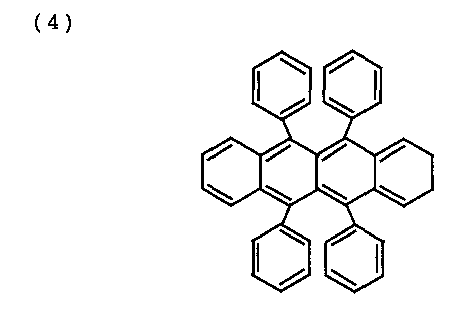
- A drive voltage was applied to the organic EL element by a DC driving system and a pulse driving system, and continuous luminescence experiments were conducted at room temperature, to examine the amount of luminance reduced with an elapse of time.
- In the DC driving system, a predetermined voltage was continuously applied to the organic EL element. In the pulse driving system, a pulse voltage having a duty ratio of 50 %, a pulse voltage having a duty ratio of 10 %, and a pulse voltage having a duty ratio of 1 % were applied to the organic EL element. The frequency of the pulse voltage was set to 60 Hz.
- In any of DC driving, pulse driving at a duty ratio of 50 %, pulse driving at a duty ratio of 10 %, and pulse driving at a duty ratio of 1 %, the driving conditions were adjusted such that the initial average luminance would be 100 cd/m2. The continuous luminescence experiments were conducted by constant voltage driving for keeping an average drive voltage constant. Under the driving conditions, the initial value of an average drive current was approximately 1.7 mA/cm2.
- Fig. 6 is a diagram showing the results of measurement of the duty ratio dependency of the life of the organic EL element in the example 4. In Fig. 6, the horizontal axis represents time, and the vertical axis represents relative luminance in a case where the initial average luminance is set to one.
- As shown in Fig. 6, the 70 % life was approximately one hour in the DC driving and approximately 65 hours in the pulse driving at a duty ratio of 50 %, while being significantly improved to 200 hours in the pulse driving at a duty ratio of 10 % and 300 hours in the pulse driving at a duty ratio of 1.
- In the example 5, a
luminescent layer 5 obtained by doping DCJTB having a molecular structure of a chemical formula (5) into Alq3 as a dopant for red light emission as well as doping Rubrene as a luminescence assist dopant was used. That is, the organic EL element has a stacked structure comprising ahole injection layer 3 having a thickness of 500 Å composed of 2-TNATA, ahole transport layer 4 having a thickness of 150 Å composed of á-NPB, and aluminescent layer 5 having a thickness of 400 Å composed of Alq3, DCJTB and Rubrene. The organic EL element can emit red light. However, it is lower in luminous efficiency, as compared with those in the organic EL elements emitting green light in the examples 1 to 3 and the organic EL element emitting yellow light in the example 4.
- A drive voltage was applied to the organic EL element by a DC driving system and a pulse driving system, and continuous luminescence experiments were conducted at room temperature, to examine the amount of luminance reduced with an elapse of time.
- In the DC driving system, a predetermined voltage was continuously applied to the organic EL element. In the pulse driving system, a pulse voltage having a duty ratio of 50 % and a pulse voltage having a duty ratio of 10 % were applied to the organic EL element. The frequency of the pulse voltage was set to 60 Hz.
- In any one of the DC driving, the pulse driving at a duty ratio of 50 %, and the pulse driving at a duty ratio of 10 %, the driving conditions were adjusted such that the initial average luminance would be 75 cd/m2. The continuous luminescence experiments were conducted by constant voltage driving for keeping an average drive voltage constant. Under the above-mentioned driving conditions, the initial value of an average drive current was approximately 15.6 mA/cm2.
- Fig. 7 is a diagram showing the results of measurement of the duty ratio dependency of the life of the organic EL element in the example 5. In Fig. 7, the horizontal axis represents time, and the vertical axis represents relative luminance in a case where the initial average luminance is set to one.
- As shown in Fig. 7, the 70 % life was approximately 7 hours in the DC driving, while being improved to approximately 63 hours in the pulse driving at a duty ratio of 50 % and the pulse driving at a duty ratio of 10 %.
- The results of experiments under various conditions were further added to the results of the continuous luminescence experiments in the examples 1 to 5, to examine the relationship between the average drive current and the life. The added results of the experiments were results in a case where the initial average luminance was set to 50 cd/m2 in the organic EL element, emitting green light, comprising a luminescent layer composed of Alq3, a case where the initial average luminance was set to 10 cd/m2 in the organic EL element, emitting red light, comprising a luminescent layer obtained by doping DCJTB and Rubrene into Alq3, and a case where the initial average luminance was set to 2000 cd/m2 in the organic EL element, emitting yellow light, comprising a luminescent layer obtained by doping Rubrene into α-NPB.
- Fig. 8 is a diagram showing the relationship between the initial value of the average drive voltage and the life. In Fig. 8, the horizontal axis represents the initial value of the average drive current, and the vertical axis represents the ratio of the 70 % life in the pulse driving at a duty ratio of 10 % to the 70 % life in the DC driving as the improvement rate of the life.
- As shown in Fig. 8, it is found that the improvement rate of the life by the pulse driving at a duty ratio of 10 % is low when the initial value of the average drive current is more than 3 mA/cm2 irrespective of the difference in the luminescent color and the element structure, while being significantly increased when the initial value of the average drive current is not more than 3 mA/cm2.
- As described in the foregoing, it is found that the maximum effect of attaining long life is obtained by driving the organic EL element under driving conditions, that is, a duty ratio of not more than 10 %, an average drive current of not more than 3 mA/cm2, and an average drive voltage of not more than 4 volts in consideration of the fact that the same effect of improving life can be also obtained, if the duty ratio of the pulse voltage is not more than 10 %, in cases where the duty ratio of the pulse voltage is 1 % and is 0.2 %.
- Fig. 9 is a block diagram showing an example of the configuration of a display of a simple matrix system (a passive system) using the driving device according to the present invention.
- In the display shown in Fig. 9, a plurality of organic EL elements having the structure shown in Fig. 1 are arranged in the form of a matrix of n rows and m columns on a common substrate, where n and m are arbitrary integers.
- Anodes 2 (see Fig. 1) of a plurality of
organic EL elements 20 forming each row are connected to adriving signal line 31. A plurality of drivingsignal lines 31 corresponding to a plurality of rows are connected to arow driver 30. Driving signals are respectively applied to the plurality of drivingsignal lines 31 by therow driver 30. - Cathodes 6 (see Fig. 1) of a plurality of
organic EL elements 20 forming each column are connected to a columnselection signal line 41. A plurality of columnselection signal lines 41 corresponding to a plurality of columns are connected to acolumn driver 40. Column selection signals are successively applied to the plurality of columnselection signal lines 41 by thecolumn driver 40. - The driving signal applied to the
driving signal line 31 by the row driver and the column selection signal applied to the columnsignal selection line 41 by thecolumn driver 40 are set such that a pulse voltage having a duty ratio of not more than 10 % is applied to theorganic EL element 20 which should emit light, and no pulse voltage is applied to the organic EL element which does not emit light. - In this case, an average drive current flowing through the
organic EL element 20 which should emit light is set to not more than 3 mA/cm2, and an average drive voltage applied to theorganic EL element 20 was set to not more than 4 volts. Consequently, a high definition display of a simple matrix system is realized. - Although the present invention has been described and illustrated in detail, it is clearly understood that the same is by way of illustration and example only and is not to be taken by way of limitation, the spirit and scope of the present invention being limited only by the terms of the appended claims.
Claims (10)
- A method of driving an organic electroluminescence element including an organic material layer, comprising the step of:applying a pulse voltage having a duty ratio of not more than 10 % between electrodes in said organic electroluminescence element, setting an average drive current flowing through said organic electroluminescence element to not more than 3 mA/cm2, and setting an average drive voltage applied between the electrodes in said organic electroluminescence element to not more than 4 volts.
- The driving method according to claim 1, wherein
said step of setting the average drive voltage to not more than 4 volts comprises the step of setting said average drive voltage to not more than 1 volt. - The driving method according to claim 1, wherein
said organic material layer includes an aluminum quinolinol complex. - An apparatus for driving an organic electroluminescence element including an organic material layer, comprising:a pulse voltage application circuit for applying a pulse voltage having a duty ratio of not more than 10 % between electrodes in said organic electroluminescence element, whereinan average drive current flowing through said organic electroluminescence element is set to not more than 3 mA/cm2, and an average drive voltage applied between the electrodes in said organic electroluminescence element is set to not more than 4 volts.
- The driving apparatus according to claim 4, wherein
said average drive voltage is set to not more than 1 volt. - The driving apparatus according to claim 4, wherein
said organic electroluminescence element comprises an organic material layer containing an aluminum quinolinol complex. - A display comprising:one or a plurality of organic electroluminescence elements each including an organic material layer, anda driving device for applying a pulse voltage having a duty ratio of not more than 10 % between electrodes in each of the organic electroluminescence elements, whereinan average drive current flowing through each of the organic electroluminescence elements is set to not more than 3 mA/cm2, and an average drive voltage applied between the electrodes in each of the organic electroluminescence elements is set to not more than 4 volts.
- The display according to claim 7, wherein
said driving device is a driving device of a simple matrix system. - The display according to claim 7, wherein
the average drive voltage applied between the electrodes in each of the organic electroluminescence elements is set to not more than 1 volt. - The display according to claim 7, wherein
said organic material layer contains an aluminum quinolinol complex.
Applications Claiming Priority (2)
| Application Number | Priority Date | Filing Date | Title |
|---|---|---|---|
| JP2000288011A JP2002100470A (en) | 2000-09-22 | 2000-09-22 | Driving method and driving device for organic electroluminescence element and display device using the same |
| JP2000288011 | 2000-09-22 |
Publications (2)
| Publication Number | Publication Date |
|---|---|
| EP1197942A2 true EP1197942A2 (en) | 2002-04-17 |
| EP1197942A3 EP1197942A3 (en) | 2005-03-09 |
Family
ID=18771669
Family Applications (1)
| Application Number | Title | Priority Date | Filing Date |
|---|---|---|---|
| EP01308001A Withdrawn EP1197942A3 (en) | 2000-09-22 | 2001-09-19 | Method of driving organic electroluminescence element, apparatus for driving organic electroluminescence element and display using the same |
Country Status (3)
| Country | Link |
|---|---|
| US (1) | US20020041162A1 (en) |
| EP (1) | EP1197942A3 (en) |
| JP (1) | JP2002100470A (en) |
Cited By (2)
| Publication number | Priority date | Publication date | Assignee | Title |
|---|---|---|---|---|
| WO2004023443A3 (en) * | 2002-09-09 | 2004-06-10 | Du Pont | Organic electronic device having improved homogeneity |
| US9153168B2 (en) | 2002-07-09 | 2015-10-06 | Semiconductor Energy Laboratory Co., Ltd. | Method for deciding duty factor in driving light-emitting device and driving method using the duty factor |
Families Citing this family (6)
| Publication number | Priority date | Publication date | Assignee | Title |
|---|---|---|---|---|
| EP1434469A4 (en) * | 2001-08-09 | 2006-08-09 | Idemitsu Kosan Co | ORGANIC ELECTROLUMINESCENT SCREEN AND METHOD OF CONTROLLING THE SAME |
| JP2004046218A (en) * | 2002-07-09 | 2004-02-12 | Semiconductor Energy Lab Co Ltd | Method for determining duty ratio of driving of light emitting device and driving method using same duty ratio |
| TW200541401A (en) | 2004-02-13 | 2005-12-16 | Idemitsu Kosan Co | Organic electroluminescent device |
| CN100472834C (en) * | 2004-10-26 | 2009-03-25 | 中国科学院长春应用化学研究所 | Organic light-emitting diode with waterfall carrier trapping structure and its manufacturing method |
| JP5880274B2 (en) | 2012-05-21 | 2016-03-08 | コニカミノルタ株式会社 | Organic electroluminescence element, lighting device and display device |
| CN109410843B (en) * | 2019-01-04 | 2020-07-24 | 京东方科技集团股份有限公司 | Method and device for driving electroluminescent device and electroluminescent device |
Citations (1)
| Publication number | Priority date | Publication date | Assignee | Title |
|---|---|---|---|---|
| EP0961330A2 (en) * | 1998-05-19 | 1999-12-01 | SANYO ELECTRIC Co., Ltd. | Organic electroluminescent device |
Family Cites Families (2)
| Publication number | Priority date | Publication date | Assignee | Title |
|---|---|---|---|---|
| JPH10199674A (en) * | 1996-11-15 | 1998-07-31 | Sanyo Electric Co Ltd | Driving method of organic electroluminescence element, organic electroluminescence device and display device |
| JP3884564B2 (en) * | 1998-05-20 | 2007-02-21 | 出光興産株式会社 | Organic EL light emitting device and light emitting device using the same |
-
2000
- 2000-09-22 JP JP2000288011A patent/JP2002100470A/en active Pending
-
2001
- 2001-09-18 US US09/954,210 patent/US20020041162A1/en not_active Abandoned
- 2001-09-19 EP EP01308001A patent/EP1197942A3/en not_active Withdrawn
Patent Citations (1)
| Publication number | Priority date | Publication date | Assignee | Title |
|---|---|---|---|---|
| EP0961330A2 (en) * | 1998-05-19 | 1999-12-01 | SANYO ELECTRIC Co., Ltd. | Organic electroluminescent device |
Non-Patent Citations (1)
| Title |
|---|
| MATSUURA, M. ET AL: "Performance of RGB Multi-Color Organic EL Display", ASIA DISPLAY'95, 16 October 1995 (1995-10-16), pages 269 - 272 * |
Cited By (3)
| Publication number | Priority date | Publication date | Assignee | Title |
|---|---|---|---|---|
| US9153168B2 (en) | 2002-07-09 | 2015-10-06 | Semiconductor Energy Laboratory Co., Ltd. | Method for deciding duty factor in driving light-emitting device and driving method using the duty factor |
| WO2004023443A3 (en) * | 2002-09-09 | 2004-06-10 | Du Pont | Organic electronic device having improved homogeneity |
| US7385572B2 (en) | 2002-09-09 | 2008-06-10 | E.I Du Pont De Nemours And Company | Organic electronic device having improved homogeneity |
Also Published As
| Publication number | Publication date |
|---|---|
| US20020041162A1 (en) | 2002-04-11 |
| JP2002100470A (en) | 2002-04-05 |
| EP1197942A3 (en) | 2005-03-09 |
Similar Documents
| Publication | Publication Date | Title |
|---|---|---|
| JP3063453B2 (en) | Driving method of organic thin film EL element | |
| KR100488835B1 (en) | Semiconductor device and display device | |
| US7248237B2 (en) | Display device and display device driving method | |
| KR100489272B1 (en) | Organic electroluminescence device and method for driving the same | |
| US6023259A (en) | OLED active matrix using a single transistor current mode pixel design | |
| KR100926591B1 (en) | Organic electroluminescent display | |
| US6429601B1 (en) | Electroluminescent devices | |
| US6911960B1 (en) | Active-type electroluminescent display | |
| JP4181795B2 (en) | Electroluminescence element | |
| JPH11185957A (en) | Organic electroluminescent element and organic electroluminescent device | |
| KR20090106162A (en) | OLED display and driving method thereof | |
| US7561126B2 (en) | Method of driving electroluminescent device | |
| KR20050031395A (en) | Organic el panel | |
| JP2003330418A (en) | Display device and driving method thereof | |
| US7202840B2 (en) | Method for driving an organic electroluminescent display device | |
| KR20220091166A (en) | Organic Light Emitting Diode Display Device | |
| US20020041162A1 (en) | Method of driving organic electroluminescence element, apparatus for driving organic electroluminescence element and display using the same | |
| EP1085496A2 (en) | Driving method and drive for organic electroluminescence element and display employing the same | |
| JPH10172767A (en) | Electroluminescence device and display device | |
| US7847766B2 (en) | Self-emission display apparatus and method of driving the same | |
| JP2002100471A (en) | Driving method and driving device for organic electroluminescence element and display device using the same | |
| JP2002196706A (en) | Simple matrix type display device | |
| KR100489166B1 (en) | Amoled | |
| US9153168B2 (en) | Method for deciding duty factor in driving light-emitting device and driving method using the duty factor | |
| US20070207344A1 (en) | Organic Electroluminescent Device and Display Apparatus Using the Same |
Legal Events
| Date | Code | Title | Description |
|---|---|---|---|
| PUAI | Public reference made under article 153(3) epc to a published international application that has entered the european phase |
Free format text: ORIGINAL CODE: 0009012 |
|
| AK | Designated contracting states |
Kind code of ref document: A2 Designated state(s): AT BE CH CY DE DK ES FI FR GB GR IE IT LI LU MC NL PT SE TR |
|
| AX | Request for extension of the european patent |
Free format text: AL;LT;LV;MK;RO;SI |
|
| PUAL | Search report despatched |
Free format text: ORIGINAL CODE: 0009013 |
|
| AK | Designated contracting states |
Kind code of ref document: A3 Designated state(s): AT BE CH CY DE DK ES FI FR GB GR IE IT LI LU MC NL PT SE TR |
|
| AX | Request for extension of the european patent |
Extension state: AL LT LV MK RO SI |
|
| 17P | Request for examination filed |
Effective date: 20050901 |
|
| AKX | Designation fees paid |
Designated state(s): DE FR GB |
|
| STAA | Information on the status of an ep patent application or granted ep patent |
Free format text: STATUS: THE APPLICATION IS DEEMED TO BE WITHDRAWN |
|
| 18D | Application deemed to be withdrawn |
Effective date: 20080531 |