EP1197358B1 - Procédé de fabrication d'un bras pour une suspension multi-bras - Google Patents
Procédé de fabrication d'un bras pour une suspension multi-bras Download PDFInfo
- Publication number
- EP1197358B1 EP1197358B1 EP01402520A EP01402520A EP1197358B1 EP 1197358 B1 EP1197358 B1 EP 1197358B1 EP 01402520 A EP01402520 A EP 01402520A EP 01402520 A EP01402520 A EP 01402520A EP 1197358 B1 EP1197358 B1 EP 1197358B1
- Authority
- EP
- European Patent Office
- Prior art keywords
- articulation
- mount
- mounts
- elastic
- distance
- Prior art date
- Legal status (The legal status is an assumption and is not a legal conclusion. Google has not performed a legal analysis and makes no representation as to the accuracy of the status listed.)
- Expired - Lifetime
Links
- 238000000034 method Methods 0.000 title claims description 33
- 239000000725 suspension Substances 0.000 title abstract description 5
- 238000005259 measurement Methods 0.000 claims description 12
- 230000000694 effects Effects 0.000 claims description 5
- 230000000052 comparative effect Effects 0.000 claims 1
- 238000004519 manufacturing process Methods 0.000 abstract description 24
- 229920001971 elastomer Polymers 0.000 abstract description 3
- 239000000806 elastomer Substances 0.000 abstract description 3
- 238000003754 machining Methods 0.000 description 11
- 238000009434 installation Methods 0.000 description 6
- 230000006870 function Effects 0.000 description 4
- 230000004048 modification Effects 0.000 description 4
- 238000012986 modification Methods 0.000 description 4
- 208000031968 Cadaver Diseases 0.000 description 3
- 235000008612 Gnetum gnemon Nutrition 0.000 description 3
- 240000000018 Gnetum gnemon Species 0.000 description 3
- 229910052751 metal Inorganic materials 0.000 description 3
- 239000002184 metal Substances 0.000 description 3
- 238000009826 distribution Methods 0.000 description 2
- 239000013536 elastomeric material Substances 0.000 description 2
- 230000033001 locomotion Effects 0.000 description 2
- 230000002159 abnormal effect Effects 0.000 description 1
- 239000006096 absorbing agent Substances 0.000 description 1
- 230000004308 accommodation Effects 0.000 description 1
- 229910052782 aluminium Inorganic materials 0.000 description 1
- XAGFODPZIPBFFR-UHFFFAOYSA-N aluminium Chemical compound [Al] XAGFODPZIPBFFR-UHFFFAOYSA-N 0.000 description 1
- 230000006399 behavior Effects 0.000 description 1
- 210000000080 chela (arthropods) Anatomy 0.000 description 1
- 230000007423 decrease Effects 0.000 description 1
- 239000006185 dispersion Substances 0.000 description 1
- 238000001914 filtration Methods 0.000 description 1
- 239000003550 marker Substances 0.000 description 1
- 239000000463 material Substances 0.000 description 1
- 230000010355 oscillation Effects 0.000 description 1
- 230000001105 regulatory effect Effects 0.000 description 1
- 230000035939 shock Effects 0.000 description 1
- 239000007787 solid Substances 0.000 description 1
- 238000003466 welding Methods 0.000 description 1
Images



Classifications
-
- B—PERFORMING OPERATIONS; TRANSPORTING
- B60—VEHICLES IN GENERAL
- B60G—VEHICLE SUSPENSION ARRANGEMENTS
- B60G7/00—Pivoted suspension arms; Accessories thereof
- B60G7/001—Suspension arms, e.g. constructional features
-
- B—PERFORMING OPERATIONS; TRANSPORTING
- B60—VEHICLES IN GENERAL
- B60G—VEHICLE SUSPENSION ARRANGEMENTS
- B60G2200/00—Indexing codes relating to suspension types
- B60G2200/10—Independent suspensions
- B60G2200/18—Multilink suspensions, e.g. elastokinematic arrangements
-
- B—PERFORMING OPERATIONS; TRANSPORTING
- B60—VEHICLES IN GENERAL
- B60G—VEHICLE SUSPENSION ARRANGEMENTS
- B60G2204/00—Indexing codes related to suspensions per se or to auxiliary parts
- B60G2204/10—Mounting of suspension elements
- B60G2204/14—Mounting of suspension arms
- B60G2204/143—Mounting of suspension arms on the vehicle body or chassis
-
- B—PERFORMING OPERATIONS; TRANSPORTING
- B60—VEHICLES IN GENERAL
- B60G—VEHICLE SUSPENSION ARRANGEMENTS
- B60G2204/00—Indexing codes related to suspensions per se or to auxiliary parts
- B60G2204/10—Mounting of suspension elements
- B60G2204/14—Mounting of suspension arms
- B60G2204/148—Mounting of suspension arms on the unsprung part of the vehicle, e.g. wheel knuckle or rigid axle
-
- B—PERFORMING OPERATIONS; TRANSPORTING
- B60—VEHICLES IN GENERAL
- B60G—VEHICLE SUSPENSION ARRANGEMENTS
- B60G2204/00—Indexing codes related to suspensions per se or to auxiliary parts
- B60G2204/40—Auxiliary suspension parts; Adjustment of suspensions
- B60G2204/41—Elastic mounts, e.g. bushings
-
- B—PERFORMING OPERATIONS; TRANSPORTING
- B60—VEHICLES IN GENERAL
- B60G—VEHICLE SUSPENSION ARRANGEMENTS
- B60G2206/00—Indexing codes related to the manufacturing of suspensions: constructional features, the materials used, procedures or tools
- B60G2206/01—Constructional features of suspension elements, e.g. arms, dampers, springs
- B60G2206/10—Constructional features of arms
- B60G2206/11—Constructional features of arms the arm being a radius or track or torque or steering rod or stabiliser end link
-
- B—PERFORMING OPERATIONS; TRANSPORTING
- B60—VEHICLES IN GENERAL
- B60G—VEHICLE SUSPENSION ARRANGEMENTS
- B60G2206/00—Indexing codes related to the manufacturing of suspensions: constructional features, the materials used, procedures or tools
- B60G2206/01—Constructional features of suspension elements, e.g. arms, dampers, springs
- B60G2206/90—Maintenance
- B60G2206/91—Assembly procedures
Definitions
- the invention relates to the field of automobile suspensions.
- Multi-link axles are equipped with a plurality of arms which are articulated for each wheel side, of a part of the vehicle such as the hub and, on the other hand, on another part of the vehicle such as the body or the cradle of the vehicle.
- the respective dispositions of the arms form an arrangement which defines an angle of the hub by relationship to the fund, which will depend in particular on the angle of wheel clamp that will be mounted on the hub.
- half-axle Given the symmetry of such an axle compared to the longitudinal axis of the vehicle, hereinafter referred to as "half-axle" the part of the axle relating to the same wheel, left or right.
- such arms have at least two openings that house tightly two knuckle blocks elastic.
- These blocks are each formed of a ring internal and an outer ring, with an elastic link connecting the two rings.
- the axis of the inner ring defines substantially a general axis of articulation, while the axis of the outer ring substantially defines a general axis of block.
- the distance between the axes of the rings two blocks of an arm corresponding to the distance between the two axes of articulation of the arm (and which defines the "useful" length of this arm), should respect tolerances narrow.
- articulation blocks are known, for example example of the ball type, which do not have a characteristic of eccentricity between the axis of articulation and the axis block but do not have characteristics either elasticity and do not allow the filtering of oscillations.
- the present invention improves the situation for arms provided with at least one elastic hinge block.
- step a) further comprises an operation of jointly the angular position of the articulation block or blocks elastic and the distance between the two axes of blocks, by adjusting one of these magnitudes relative to the other in function of a desired distance between the two axes of articulation and taking into account a residual eccentricity between the inner ring and the outer ring of the block or blocks elastic articulation.
- step b) the elastic articulation block or blocks are housed tightly in an angular position account of adjusted size.
- the method of the invention makes it possible to respect limited tolerances on the desired distance, with hinge blocks mounted in their housing, compensating the effect of residual eccentricity between the rings internal and external of the elastic articulation block or blocks.
- the arm thus manufactured can therefore comprise two blocks elastic hinge, or a hinge block elastic and a block of different type, such as a block ball joint type.
- step a) comprises a measurement of the position and the value of the residual eccentricity of rings of the elastic articulation block or blocks.
- step b) the articulation blocks are then housed in openings in angular positions taking into account the adjusted size.
- the process within the meaning of the present invention, can be decline according to at least three main embodiments.
- This first embodiment is as well adapted to the manufacture of an arm provided with a ball joint and of an elastic articulation block than to the manufacture of a arm with two elastic hinge blocks.
- the elastic link of each block may possess circumferentially elastic properties not isotropic.
- the first block whose angular position is fixed at operation a2) can be directly introduced into its housing from operation a2), or to be introduced later, without changing its angular position.
- the above-mentioned measure of the position and the value of the eccentricity is done on the second block to be housed, prior to the operation a3).
- this second mode of achievement is also well suited to the manufacture of an arm equipped with a ball joint and a hinge block elastic than the manufacture of an arm equipped with two elastic articulation blocks.
- the elastic link of the first block housed during operation a2) may have properties circumferentially non-isotropic elastics.
- the operation a2) is preferentially preceded by a measurement comparison of the residual eccentricity values of the two blocks, the first block housed being the one of the weakest eccentricity.
- the two blocks are elastic hinge blocks and step a) comprises a adjustment of the angular positions of the two blocks in orienting their eccentricity substantially perpendicularly to the large size of the arm body.
- the offsets are oriented substantially in the same sense of a direction perpendicular to the large size of the arm body.
- the distance between the inner rings of the blocks in their housing, after step b) of the method according to the invention advantageously meets tolerances better than two tenths of a millimeter and preferentially better than the tenth of a millimeter.
- the present invention also aims at an arm intended to be articulated to two distinct elements, in particular of a motor vehicle, this arm comprising two openings and two articulation blocks each having a general axis block and a general axis of articulation. Both blocks are housed tightly in openings and at least one is an elastic joint block with a link elastic connecting an inner ring defining axis substantially the axis of articulation and an outer ring axis substantially defining the block axis.
- the angular position of the block (s) of elastic articulation in its (their) opening is chosen according to the distance openings to maintain a desired distance between the articulation axes of the blocks.
- the center distance of the openings is chosen according to the angular position of the block (s) of elastic articulation in its (their) opening to respect a desired distance between the articulation axes of the blocks.
- the present invention applies advantageously but non-limiting to an arm for a half-axle of a vehicle automobile.
- Multi-link semi-axles manufactured in mass production usually comprise an adjusting member, for example arranged on a clamp rod, which allows, after assembly of the half-axle, to adjust the hub angle within the limits of acceptable tolerances by changing the effective length of this connecting rod.
- the clamp rod must therefore comprise a regulating member (such as a threaded rod system with nut, or a eccentric connected to the body) and a setting operation of the clamp rod must be done in final to adjust the angle of the hub.
- a regulating member such as a threaded rod system with nut, or a eccentric connected to the body
- the present invention also aims at a half-axle for a motor vehicle, this half-axle comprising a plurality of arms and joints connecting the arms, a side, to a wheel hub and, on the other hand, to the body of the vehicle, following an arrangement to define an angle hub relative to the body.
- the half-axle comprises at least one articulated arm according to the invention, and the arrangement mentioned above is achieved by adjusting the position and / or the angular orientation of each joint block elasticity in its housing, in order to define the angle of hub relative to the body following limited tolerances.
- the half-axle can operate without adjusting member the angle of the hub relative to the body.
- this angle corresponds to the pinch angle of a wheel intended to be mounted on the hub.
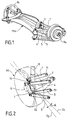
- multi-link axle comprises a plurality of arms 1 to 4, articulated, on the one hand, to the crossbar TRA of a vehicle automobile, also known as the rear cradle, and, on the other a hub 9A, 9B for carrying a wheel RO of the vehicle.
- this multi-link half-axle comprises a upper rear arm 1, one upper front arm 2, one arm lower back 4, and a lower front arm 3.
- These arms each comprise a hinge block 11 connected directly or through the TRA crossbar at the cash desk vehicle (not shown) and another hinge block 12 connected to a pivot 7 carrying the hub 9 of the wheel RO.
- the arm referenced 4 in Figure 2 called “lower arm in the example shown, a support for a suspension element 8, such as a shock absorber and / or a spring.
- the arms of the half-axle can be articulated, on the one hand, at the hub and, on the other hand, at the cash chassis of the vehicle, possibly via a component such as a cradle, or a filtered cross.
- the half-axle of FIG. 2 comprises a fifth arm 5 said "connecting rod” which is also connected to the pivot 7, of a on the other hand, and at the vehicle's cash desk (directly or indirectly), on the other hand.
- the rod 5 is intended to define a clamp angle of the wheel both at rest and when the suspension is requested.
- This rod of the half-axle of the prior art is distinguished from other arms by a means for adjusting the position of its articulation blocks 51 and / or 52, this adjustment being carried out after the assembly of the set of arms in the half-axle.
- the direction D1 indicates the longitudinal axis of the vehicle, while the direction D2 indicates the projection of the right D1 on the vehicle wheel plane.
- the angle ⁇ between these two directions D1 and D2 represents the wheel clamp angle RO.
- the behavior of the vehicle is directly related to the angle that form the hub with the vehicle body, and in particular at the clamp angle and its variations.
- An incorrect angle leads to oversteer or understeer, which is accompanied by vehicle instability, abnormal wear of the pneumatic, etc.
- the adjusting members of the clamp rod 5 allow then adjust the clamp angle ⁇ to a prescribed value.
- the gap between the initial clamp angle and the clamp angle adjusted is mainly due to uncertainties about manufacturing tolerances of the prior art arms.
- an articulated arm comprises an arm body 13 provided with two openings 131 and 132 which are intended to receive articulation blocks, elastic in the example described.
- the openings 131 and 132 can be arranged in the arm body 13 by machining, or by forming.
- the body at least one of the arms of the half-axle can be molded, forged, tubular, or made in a profile extruded aluminum, or in stamped sheet metal.
- an elastic hinge block 11 comprises an elastomeric ring 112, of general shape hollow cylindrical, internally fixed to an internal cage 113 and externally an outer cage 111.
- the outer cage 111 is preferably made in the form of a ring metal, integral with the outer surface of the ring elastomer 112 and the inner cage 113 is preferentially made in the form of a metal inner ring, integral with the inner surface of the elastomeric ring 112.
- Two articulation blocks of the type shown in FIG. 4 are then housed in the openings 131 and 132 of the body of arm 13 to form the articulated arm 1, ready to be mounted in a half-axle of the type shown in one of the figures 1 and 2.
- these elastic articulation blocks are force-fitted, in a manner known per se, in the openings 131 and 132, their outer rings 111 being housed tightly in these openings.
- the openings 131 and 132 are, in one embodiment, arranged in the arm body 13 by forming flanges for fitting forcibly subsequent articulation blocks 11 and 12. They can also be arranged in the openings of the arm body 13 by inserting cylindrical bushings therein maintained for example by welding.
- the statistical distribution of eccentricity between the inner and outer rings of a hinge block elastic follows a Gaussian law, with a maximum value eccentricity of the order of 0.75 to 1 mm.
- the precision of the realization of the distance between the openings 131 and 132 of the arm body 13 is of the order of 0.1 mm.
- the variation likely to occur on the distance d1 (FIG. 5) between the axes of the internal rings of the articulation blocks, once mounted in their housing, is of the order of 1.5 to 2 mm for the arms of the state of the technique considering the presence of two joints elastic.
- the variance on the distribution of the desired distance between the axes of the internal rings of the blocks is in particular equal to the sum of the variances on the offsets of each of the two blocks and the variance on the distance between dwellings 131 and 132 (so about twice the variance on the eccentricity of a block).
- the manufacturing process of an arm comprises a first step of arrange the two elastic hinge blocks 11 and 12 in an assembly of measurement of distances.
- the articulation blocks are centered on their inner ring, so that the distance between the axes of the respective inner rings of the two blocks corresponds to the desired value d1.
- an arm body 13 comprising at plus an opening 131.
- the second opening 132 is arranged in the arm body 13 so that the center distance of the openings 131 and 132 is equal to the distance between the axes of the rings external of both blocks 11 and 12 to manufacturing tolerances near. The manufacturing process then continues with a force fit of blocks 11 and 12 without modification their angular position.
- the two openings 131 and 132 are then machined or formed according to the center distance corresponding to this measure. It can also be planned to machine or first form an opening, then measure the distance between the outer rings of the blocks 11 and 12 and then machine or form the other opening in applying as aperture distance the distance that corresponds to this measurement.
- the resulting arm then comprises the two articulation blocks housed tightly in openings 131 and 132, with a distance d1 between the axes of the internal rings of the blocks 11 and 12, which is the distance d1 desired, tolerance machining or forming near openings 131 and 132 in the arm body 13.
- the current precisions machining or forming two openings in a blank of arms are better than 0.1 mm.
- the distance between axes of the inner rings of the blocks is consistent with the distance d1 desired. Nevertheless, the distance between openings varies function of the residual offsets of the rings of the two blocks, the position of the two blocks being chosen arbitrarily.
- the variance of the distance between the axes of the rings internal is equal to the variance on the manufacturing tolerance of the entr'axe of the openings which is much more weak than that on the eccentricity of the blocks.
- the method of manufacturing a arm according to a second embodiment of the present invention provides for a prior arrangement of the openings 131 and 132 at a desired distance of distance equal to the distance d1 searched between the axes of the internal rings.
- this block 11 is directly housed in the opening 131.
- a reference mark indicates the fixed angular position and the block 11 is introduced later.
- the other hinge block 12 undergoes a measurement of its eccentric e, before being mounted in the other housing 132, free, arm body 13.
- the hinge block 11, already mounted, and the hinge block 12, before being mounted are arranged both in a measuring fixture.
- the hinge block 11, already mounted, and the hinge block 12, before being mounted are arranged both in an assembly with a distance d1 separating the axes of their inner ring.
- the hinge block 12 undergoes then a rotation around the axis of its inner ring, to an angular position, chosen according to its eccentricity e, in which the axes of the outer rings hinge blocks 11 and 12 are separated from the distance between openings of the openings 131 and 132 of the arm body 13.
- this block 12 is forced into the opening remaining 132, without changing its angular position.
- the two articulation blocks 11 and 12 are first placed in an eccentric measuring fixture. After comparison of the excentrations of blocks 11 and 12, the first block housed in one of the openings of the arm body 13, is the one of the weakest eccentration.
- the variance over the desired distance d1 is advantageously equal to the variance on the machining or forming of the center distance.
- the resulting arm includes the two blocks articulated in a tight way, with the distance desired d1 between the axes of the inner rings respecting tolerances better than 0.1 mm, since the center distance openings remains in accordance with the distance d1 desired, tolerances for machining or forming close.
- the method of manufacturing an arm according to a third embodiment of the invention provides first of all the respective measurements eccentric e1 and e2 blocks 11 and 12. These measures are followed by an orientation of the two articulation blocks 11 and 12, so that their respective eccentric e1 and e2 are both parallel to the same direction, substantially perpendicular to the large dimension of the body arm 13 (vertical in the example shown in FIG. 9B).
- the direction of the eccentrations is the even between the two articulation blocks 11 and 12 (arrows e1 and e2).
- the two articulation blocks 11 and 12 are then mounted in the openings of the arm body 12, previously equipped with a distance of between 1 and 1, this distance d1 defining then the distance between the axes of the rings internal blocks.
- the direction of the residual eccentrations rings of the two blocks, mounted in their housing, are conserved and remains substantially perpendicular to the large arm dimension (Figure 9C).
- the center distance of the openings is in accordance with the distance d1 desired, tolerances for machining or forming close.
- the distance between the axes of the inner rings of the blocks is in accordance with this distance d1, to the measurement and machining tolerances or of forming, to which should be added a tolerance due to a difference (1 mm maximum) of the eccentricities residuals between the two blocks.
- this tolerance for a perpendicular orientation of the eccentrations, esteem itself by making the connection between this difference maximum of offsets and the distance between openings (about 400 mm). It remains less than 0.1 mm.
- Substantially perpendicular means a direction eccentrations forming an angle of between 80 ° and 100 ° with the large size of the arm body, which allows for keep a tolerance of less than 0.2 mm.
- the angular positions of the articulation blocks elastic in their housing and the distance between openings housing are mutually adjusted to meet a desired distance between the axes of the inner rings of the two blocks, so the variance over the desired distance d1 is statistically lower than the sum of the variances on the excentrations of the blocks and on the tolerance of realization of the center distance.
- the present invention also aims at an automated installation for mass production of articulated arms according to one of the three embodiments described above.
- the installation shown in Figure 6 includes a first station P1 to which articulation blocks are routed elastic 11 and 12, and a blank arm 13.
- the second P2 station is a measurement station.
- a manipulator robot grips the hinge blocks 11 and 12 for example by their inner ring so as to focus on it.
- the item P2 is provided with means for measuring center distances. It can also be equipped with means for rotating a block (for the implementation of the method according to the second embodiment) or both blocks (for the implementation of the method according to the third embodiment) and one or two feelers PA1, PA2, in contact with the outer surface of their outer ring, for measure the value of a residual eccentricity e1, e2 between the inner and outer rings of the hinge blocks, as well than the angular position of this eccentricity.
- This controller notably comprises a processor and a non-volatile memory, to which the processor has access.
- this memory comprises a calculation module angular positions of the blocks and / or the center distance of openings to apply, depending on the distance d1 that is desired between the axes of the inner rings of the blocks, a once housed.
- the present invention also aims at a such a calculation module. Means for rotating the station P2 make it possible to position the blocks in the position determined by the controller.
- the articulation blocks 11 and 12 whose angular position is, if necessary, adjusted, are forced into the openings 131 and 132 of the arm body, without modification of their angular position.
- a robot is used to transfer blocks 11 and 12 which retains the positions angular blocks fixed at the P2 station.
- an articulated arm 1 ready to be mounted to form, with the other arms, the half-axle multi-links within the meaning of the present invention.
- a marker at station P2 applies to outer surfaces of blocks 11 and 12 a sign (such as a notch) indicating the orientation of their eccentricity, or more generally the angular position they must occupy in the housing of the draft arms to respect the desired distance d1 between the axes of their ring internally, in particular for the implementation of the process according to second and the third embodiment.
- this sign may indicate a direction and a perpendicular direction to the large size of the arm body, to index the subsequent mounting of the blocks in the openings 131 and 132.
- the P3 machining station and the fitting station P4, on the one hand, and the measurement and orientation station P2, on the other hand, can be distant.
- he can be provided an installation with machining stations or forming roughing arms and introducing blocks into the arm body openings, while the blocks of articulation are delivered to the introductory position with a marking that indexes their introduction into their housing.
- the post P1 can directly include force-fitting means of the first articulation block 11 in an opening of the arm body.
- the arm manufactured taking into account the orientation of its articulation blocks and the distance between the openings of the body of arms, has a gap between the inner ring of the blocks articulation that respects a desired distance, with a very satisfactory precision (of the order of one tenth millimeter).
- the multi-link half-axle, including arms manufactured according to the invention respects the clamp angle ⁇ with the tolerances prescribed.
- the clamp rod for adjustment the angle ⁇ can be deleted.
- the elastic articulation blocks can be made from a material ring solid elastomer (as described above), or realized from an elastomeric ring comprising cells ( Figure 10) and whose elastic properties are, for therefore, not isotropic.
- An articulated arm of which both articulating blocks are of non elastic properties isotropic is preferably manufactured according to the first described embodiment, since the angular position articulation blocks 11 and 12 are not modified at course of the method according to this first embodiment.
- An articulated arm comprising an elastic articulation block only whose elastic properties are non-isotropic will be preferentially manufactured according to the second mode of embodiment described above.
- This elastic articulation block not isotropic will be the first housed in the opening of the arm blank 13 since its angular position is not modified during this process.
- the present invention also applies to an arm comprising more than two articulation blocks, such as a triangulated arm.
- An adjustment of the angular positions of the blocks connected to the body and / or an adjustment of the two ap centers of openings so that each distance between the axis of the inner ring of the blocks connected to the body and the axis of the inner ring of the block connected to the hub is in conformity at a desired distance.
- this invention can also be applied to an arm of which one of joints is elastic, while the other joint is of the ball type.
- a ball joint type defines a movement inscribed in a cone.
- the present invention is not limited to manufacture of an arm for a half-axle for a vehicle automobile. It can also apply to the manufacture an arm for the support of other equipment of the vehicle, for example to an arm or rod at least for the support or control of the motions of the engine block of the vehicle.
Landscapes
- Engineering & Computer Science (AREA)
- Mechanical Engineering (AREA)
- Vehicle Body Suspensions (AREA)
- Manufacture Of Motors, Generators (AREA)
- Axle Suspensions And Sidecars For Cycles (AREA)
- Steering Devices For Bicycles And Motorcycles (AREA)
Description
- la distance entre les axes des bagues externes respectives des deux blocs,
- la position angulaire de l'un des deux blocs, et
- la position angulaire de l'autre bloc,
- la figure 1 représente un essieu arrière d'un véhicule automobile, dit "multi-liens", comprenant une pluralité de bras articulés ;
- la figure 2 représente schématiquement un autre demi-essieu multi-liens, dit "à bras superposés", comprenant une bielle de pince ;
- la figure 3 représente une ébauche de bras munie d'ouvertures destinées à loger des blocs d'articulation ;
- la figure 4 représente un bloc d'articulation élastique, avec une bague interne et une bague externe qui présentent, l'une par rapport à l'autre, une excentration résiduelle e ;
- la figure 5 représente schématiquement un bras articulé, prêt à être monté dans un demi-essieu multi-liens du type représenté sur la figure 2 ;
- la figure 6 représente schématiquement différents postes d'une installation pour la mise en oeuvre d'un procédé de fabrication d'un bras articulé 1 au sens de la présente invention ;
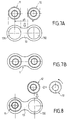
- les figures 7A et 7B représentent schématiquement deux étapes successives et un bras obtenu par un procédé selon un premier mode de réalisation de la présente invention ;
- la figure 8 représente une étape d'un procédé, selon un second mode de réalisation ;
- les figures 9A, 9B et 9C représentent des étapes successives d'un procédé, selon un troisième mode de réalisation ; et
- la figure 10 représente schématiquement un bloc d'articulation élastique comprenant un anneau en matériau élastomère, de propriétés élastiques non isotropes.
Claims (16)
- Procédé de fabrication d'un bras destiné à être articulé à deux éléments distincts (7,TRA), notamment d'un véhicule automobile, du type comprenant les opérations suivantes :caractérisé en ce que l'étape a) comprend en outre une opération consistant à fixer conjointement la position angulaire du ou des blocs d'articulation élastique (11) et la distance entre les deux axes de blocs,a) préparer au moins deux blocs d'articulation (11,12), comportant chacun un axe général de bloc et un axe général d'articulation et dont l'un au moins est un bloc d'articulation élastique comprenant un lien élastique (112) entre une bague interne (113) dont l'axe définit sensiblement l'axe d'articulation et une bague externe (111) dont l'axe définit sensiblement l'axe de bloc, ainsi qu'un corps de bras (13), avec au moins deux ouvertures (131,132) destinées à loger chacune un bloc d'articulation, etb) monter un bras prêt à être articulé, avec les deux blocs d'articulation logés de façon serrée dans lesdites ouvertures,
en ajustant l'une de ces grandeurs par rapport à l'autre, en fonction d'une distance désirée (d1) entre les deux axes d'articulation et en tenant compte d'une excentration résiduelle (e) entre la bague interne et la bague externe du ou des blocs d'articulation élastique,
et en ce que, à l'étape b), le ou les blocs d'articulation élastique sont logés de façon serrée dans une position angulaire tenant compte de la grandeur ajustée,
ce qui permet de respecter des tolérances limitées sur ladite distance désirée (d1), avec les blocs d'articulation montés dans leur logement, en compensant l'effet d'une excentration résiduelle (e) entre les bagues interne et externe du ou des blocs d'articulation élastique. - Procédé selon la revendication 1, caractérisé en ce que les deux blocs d'articulation sont tous deux des blocs d'articulation élastique (11,12),
en ce que l'étape a) comprend l'opération consistant à fixer à la fois :en ajustant l'une au moins de ces grandeurs par rapport aux autres, en fonction d'une distance désirée (d1) entre les axes des bagues internes respectives des deux blocs et en tenant compte des excentrations résiduelles (e1,e2) entre les bagues interne et externe de l'un et l'autre des blocs,la distance entre les axes des bagues externes respectives des deux blocs,la position angulaire de l'un des deux blocs, etla position angulaire de l'autre bloc,
et en ce que, à l'étape b), les blocs d'articulation sont logés dans les ouvertures (131,132) dans des positions angulaires tenant compte de la grandeur ajustée. - Procédé selon la revendication 1 ou 2, caractérisé en ce que, après l'étape b), la distance (d1) entre les axes des bagues internes des blocs d'articulation élastique dans leur logement respecte des tolérances meilleures que deux dixièmes de millimètre et préférentiellement meilleures que le dixième de millimètre.
- Procédé selon l'une des revendications 1 à 3, caractérisé en ce que l'étape a) comprend les opérations suivantes :et en ce que le procédé se poursuit par le logement des blocs dans les ouvertures, sans modification de la position angulaire du bloc d'articulation élastique.a1) positionner les blocs d'articulation sur un montage (P2) définissant une distance désirée (d1) entre les deux axes d'articulation,a2) mesurer la distance entre les deux axes de blocs, eta3) aménager les deux ouvertures (131,132) dans le corps de bras (13), en prévoyant une distance entre les ouvertures qui correspond à la distance mesurée pendant l'opération a2),
- Procédé selon l'une des revendications 1 à 3, caractérisé en ce que l'étape a) comprend une mesure de la position et de la valeur de l'excentration résiduelle (e) des bagues du ou des blocs d'articulation élastique.
- Procédé selon l'une des revendications 1 à 3, caractérisé en ce que l'étape a) comprend les opérations suivantes :et en ce que le procédé se poursuit par le logement du bloc d'articulation élastique (12) dans l'autre ouverture (132), sans modification de sa position angulaire.a1) aménager les ouvertures dans le corps de bras (13), avec une entr'axe entre les ouvertures qui correspond à ladite distance désirée (d1),a2) fixer la position angulaire de l'un des deux blocs (11) en vue de le loger dans l'une des ouvertures (131) dans cette position angulaire, en réservant le ou l'autre bloc d'articulation élastique (12) à l'opération suivante, eta3) ajuster la position angulaire de ce bloc d'articulation élastique (12) de sorte que la distance entre les deux axes d'articulation corresponde à la distance désirée (d1),
- Procédé selon la revendication 2, prise en combinaison avec la revendication 6, caractérisé en ce que l'opération a2) est précédée d'une mesure comparative (P2) de la valeur des excentrations résiduelles (e1,e2) des deux blocs (11,12), et en ce que le premier bloc logé est le bloc de plus faible excentration.
- Procédé selon l'une des revendications 1 à 3, prise en combinaison entre la revendication 5, caractérisé en ce que l'étape a) comprend en outre un ajustement de la position angulaire du ou des blocs d'articulation élastique en orientant son excentration (e1,e2) sensiblement perpendiculairement à la grande dimension du corps de bras (13).
- Procédé selon la revendication 8, prise en combinaison avec la revendication 2 caractérisé en ce que l'excentration (e1,e2) est orientée sensiblement dans un même sens d'une direction perpendiculaire à la grande dimension de l'ébauche de bras.
- Procédé selon l'une des revendications 1 à 4, caractérisé en ce que le lien du ou des blocs d'articulation élastique (112) possède des propriétés élastiques circonférenciellement non isotropes.
- Procédé selon l'une des revendications 2 à 4, caractérisé en ce que le lien (112) de chaque bloc d'articulation élastique possède des propriétés élastiques circonférenciellement non isotropes.
- Procédé selon la revendication 6, prise en combinaison avec la revendication 2, caractérisé en ce que le lien du premier bloc (11) logé pendant l'opération a2) possède des propriétés élastiques circonférenciellement non isotropes.
- Bras destiné à être articulé à deux éléments distincts, notamment d'un véhicule automobile, du type comprenant deux ouvertures (131,132) et deux blocs d'articulation (11,12) comportant chacun un axe général de bloc et un axe général d'articulation, logés de façon serrée dans les ouvertures et dont l'un au moins est un bloc d'articulation élastique comportant un lien élastique (112) reliant une bague interne (113) d'axe définissant sensiblement l'axe d'articulation et une bague externe (111) d'axe définissant sensiblement l'axe de bloc,
caractérisé en ce que la position angulaire du/des bloc(s) d'articulation élastique (11) dans son/leur ouverture (131) est choisie en fonction de l'entr'axe des ouvertures (131, 132) pour respecter une distance désirée (d1) entre les axes d'articulation des blocs, ce qui permet de compenser l'effet d'une excentration résiduelle (e) entre les bagues interne et externe du/des bloc(s) d'articulation élastique. - Bras destiné à être articulé à deux éléments distincts, notamment d'un véhicule automobile, du type comprenant deux ouvertures (131,132) et deux blocs d'articulation (11,12) comportant chacun un axe général de bloc et un axe général d'articulation, logés de façon serrée dans les ouvertures et dont l'un au moins est un bloc d'articulation élastique comportant un lien élastique (112) reliant une bague interne (113) d'axe définissant sensiblement l'axe d'articulation et une bague externe (111) d'axe définissant sensiblement l'axe de bloc,
caractérisé en ce que l'entr'axe des ouvertures (131,132) est choisie en fonction de la position angulaire du/des bloc(s) d'articulation élastique (11) dans son/leur ouverture (131) pour respecter une distance désirée (d1) entre les axes d'articulation des blocs, ce qui permet de compenser l'effet d'une excentration résiduelle (e) entre les bagues interne et externe du/des bloc(s) d'articulation élastique. - Demi-essieu pour véhicule automobile, du type comprenant une pluralité de bras et des articulations reliant les bras, d'un côté, à un moyeu porte-roue (9) et, d'un autre côté, à la caisse du véhicule, suivant un aménagement propre à définir un angle du moyeu par rapport à la caisse,
caractérisé en ce qu'il comporte au moins un bras (1) selon l'une des revendications 13 et 14,
et en ce que l'aménagement est réalisé par un ajustement de la position et/ou de l'orientation angulaire de chaque bloc d'articulation élastique (11,12) dans son logement (131,132), en vue de définir l'angle du moyeu par rapport à la caisse suivant des tolérances limitées, ce qui permet au demi-essieu de fonctionner sans organe de réglage (51,52) de cet angle. - Demi-essieu selon la revendication 15, caractérisé en ce que l'angle du moyeu correspond à l'angle de pince (α) d'une roue (RO) destinée à être montée sur le moyeu (9).
Applications Claiming Priority (2)
| Application Number | Priority Date | Filing Date | Title |
|---|---|---|---|
| FR0013011 | 2000-10-11 | ||
| FR0013011A FR2814973B1 (fr) | 2000-10-11 | 2000-10-11 | Procede de fabrication d'un bras articule, notamment pour un demi-essieu multi-liens de vechicule automobile |
Publications (2)
| Publication Number | Publication Date |
|---|---|
| EP1197358A1 EP1197358A1 (fr) | 2002-04-17 |
| EP1197358B1 true EP1197358B1 (fr) | 2003-12-17 |
Family
ID=8855230
Family Applications (1)
| Application Number | Title | Priority Date | Filing Date |
|---|---|---|---|
| EP01402520A Expired - Lifetime EP1197358B1 (fr) | 2000-10-11 | 2001-09-28 | Procédé de fabrication d'un bras pour une suspension multi-bras |
Country Status (4)
| Country | Link |
|---|---|
| EP (1) | EP1197358B1 (fr) |
| AT (1) | ATE256566T1 (fr) |
| DE (1) | DE60101533T2 (fr) |
| FR (1) | FR2814973B1 (fr) |
Families Citing this family (6)
| Publication number | Priority date | Publication date | Assignee | Title |
|---|---|---|---|---|
| DE102010043038A1 (de) * | 2010-10-28 | 2012-05-03 | Zf Friedrichshafen Ag | Verfahren zur Herstellung eines Fahrwerkbauteils |
| DE102010043456A1 (de) * | 2010-11-05 | 2012-05-10 | Bayerische Motoren Werke Aktiengesellschaft | Exzentrisches Gummilager eines radführenden Lenkers und Einbau eines solchen in der Radaufhängung eines Fahrzeugs |
| DE102013002705A1 (de) | 2013-02-16 | 2014-08-21 | Audi Ag | Radaufhängung für ein Hinterrad eines zweispurigen Kraftfahrzeugs |
| EP3296198B1 (fr) | 2016-09-15 | 2018-11-14 | AIRBUS HELICOPTERS DEUTSCHLAND GmbH | Réglage de piste et équilibrage d'un rotor à pales multiples |
| DE102017206342B4 (de) | 2017-04-12 | 2023-04-27 | Ford Global Technologies, Llc | Radführungslenker für eine Radaufhängung eines Fahrzeugs |
| EP3954556A1 (fr) * | 2020-08-11 | 2022-02-16 | Volvo Truck Corporation | Palier élastique pour une suspension et véhicule comportant un tel palier |
Family Cites Families (4)
| Publication number | Priority date | Publication date | Assignee | Title |
|---|---|---|---|---|
| US3880444A (en) * | 1974-02-22 | 1975-04-29 | Alvin C Bridges | Means to adjust wheel support pivot shaft |
| US5305661A (en) * | 1992-10-05 | 1994-04-26 | Caterpillar Inc. | Apparatus and method for positioning a link |
| JPH0717229A (ja) * | 1993-06-30 | 1995-01-20 | Suzuki Motor Corp | サスペンション装置 |
| US5431540A (en) * | 1993-12-14 | 1995-07-11 | United Technologies Corporation | Main rotor pitch control rod subassembly |
-
2000
- 2000-10-11 FR FR0013011A patent/FR2814973B1/fr not_active Expired - Fee Related
-
2001
- 2001-09-28 EP EP01402520A patent/EP1197358B1/fr not_active Expired - Lifetime
- 2001-09-28 AT AT01402520T patent/ATE256566T1/de not_active IP Right Cessation
- 2001-09-28 DE DE60101533T patent/DE60101533T2/de not_active Expired - Lifetime
Also Published As
| Publication number | Publication date |
|---|---|
| EP1197358A1 (fr) | 2002-04-17 |
| FR2814973B1 (fr) | 2003-02-07 |
| ATE256566T1 (de) | 2004-01-15 |
| DE60101533T2 (de) | 2004-11-11 |
| FR2814973A1 (fr) | 2002-04-12 |
| DE60101533D1 (de) | 2004-01-29 |
Similar Documents
| Publication | Publication Date | Title |
|---|---|---|
| EP1578626B1 (fr) | Dispositif de support de roue a triple charniere, dispositif de suspension et vehicule comprenant ledit dispositif de support | |
| EP0780250A2 (fr) | Réglage précis d'une jambe de force de suspension MacPherson: moyens de réglage sur la jambe et banc de mesure | |
| EP0904211B1 (fr) | Essieu souple comportant une traverse et des bras tires | |
| WO2015079134A1 (fr) | Support de blocage pneumatique d'une lentille optique | |
| FR2872452A1 (fr) | Dispositif de suspension pour vehicule automobile | |
| FR2805776A1 (fr) | Essieu souple pour vehicule automobile, a dispositif anti- roulis perfectionne | |
| EP1272385B1 (fr) | Procede d'assemblage d'un systeme de suspension | |
| WO2012123662A1 (fr) | Dispositif de liaison d'une roue a une structure de véhicule automobile | |
| EP1197358A1 (fr) | Procédé de fabrication d'un bras pour une suspension multi-bras | |
| EP1265763B1 (fr) | Traverse d'essieu de vehicule avec articulations antiroulis et essieu de vehicule comportant une telle traverse | |
| EP1689598B1 (fr) | Essieu souple dont la raideur transversale est augmentee a l'aide d'au moins une piece formant coupelle de ressort, coupelle de ressort et vehicule correspondant | |
| EP0421864A1 (fr) | ProcédÀ© de réalisation de pièces élastiques à rigidités différenciées dans les trois directions par emmanchement de pièces cylindriques à armatures rigides | |
| EP0489638A1 (fr) | Dispositif formant suspension notamment pour une roue directrice d'un véhicule automobile | |
| EP1894818B1 (fr) | Essieu pour véhicule et cale de réglage du parallélisme d'un tel essieu | |
| FR2806693A1 (fr) | Dispositif de support d'une roue de vehicule | |
| WO1998044373A1 (fr) | Dispositif de positionnement micrometrique d'un support d'element optique spatial selon six degres de liberte | |
| EP0952015A1 (fr) | Essieu torsible | |
| FR2701901A1 (fr) | Train de roues arrière pour véhicule automobile et procédé de montage d'un tel train. | |
| FR2864471A1 (fr) | Essieu souple a bras longitudinaux cintres, bras longitudinal et vehicule correspondants | |
| FR2861335A1 (fr) | Train de vehicule incluant une liaison flexible | |
| FR3096338A1 (fr) | Amortisseur pour vehicule automobile ou motocyclette | |
| FR3086921A1 (fr) | Porte-fusee pour vehicule automobile comprenant un premier evidement et un deuxieme evidement | |
| FR2959474A1 (fr) | Entretoise permettant la correction des angles de pince et de carrossage pour le montage des roues d'un vehicule | |
| FR3161604A1 (fr) | Bras de suspension de véhicule automobile avec liaison pivot réglable | |
| EP3362304B1 (fr) | Agencement pour la liaison d'un porte fusée à un élément de structure de véhicule automobile |
Legal Events
| Date | Code | Title | Description |
|---|---|---|---|
| PUAI | Public reference made under article 153(3) epc to a published international application that has entered the european phase |
Free format text: ORIGINAL CODE: 0009012 |
|
| AK | Designated contracting states |
Kind code of ref document: A1 Designated state(s): AT BE CH CY DE DK ES FI FR GB GR IE IT LI LU MC NL PT SE TR |
|
| AX | Request for extension of the european patent |
Free format text: AL;LT;LV;MK;RO;SI |
|
| 17P | Request for examination filed |
Effective date: 20020403 |
|
| AKX | Designation fees paid |
Free format text: AT BE CH CY DE DK ES FI FR GB GR IE IT LI LU MC NL PT SE TR |
|
| GRAH | Despatch of communication of intention to grant a patent |
Free format text: ORIGINAL CODE: EPIDOS IGRA |
|
| GRAS | Grant fee paid |
Free format text: ORIGINAL CODE: EPIDOSNIGR3 |
|
| GRAA | (expected) grant |
Free format text: ORIGINAL CODE: 0009210 |
|
| AK | Designated contracting states |
Kind code of ref document: B1 Designated state(s): AT BE CH CY DE DK ES FI FR GB GR IE IT LI LU MC NL PT SE TR |
|
| PG25 | Lapsed in a contracting state [announced via postgrant information from national office to epo] |
Ref country code: IT Free format text: LAPSE BECAUSE OF FAILURE TO SUBMIT A TRANSLATION OF THE DESCRIPTION OR TO PAY THE FEE WITHIN THE PRESCRIBED TIME-LIMIT;WARNING: LAPSES OF ITALIAN PATENTS WITH EFFECTIVE DATE BEFORE 2007 MAY HAVE OCCURRED AT ANY TIME BEFORE 2007. THE CORRECT EFFECTIVE DATE MAY BE DIFFERENT FROM THE ONE RECORDED. Effective date: 20031217 Ref country code: IE Free format text: LAPSE BECAUSE OF FAILURE TO SUBMIT A TRANSLATION OF THE DESCRIPTION OR TO PAY THE FEE WITHIN THE PRESCRIBED TIME-LIMIT Effective date: 20031217 Ref country code: TR Free format text: LAPSE BECAUSE OF FAILURE TO SUBMIT A TRANSLATION OF THE DESCRIPTION OR TO PAY THE FEE WITHIN THE PRESCRIBED TIME-LIMIT Effective date: 20031217 Ref country code: GB Free format text: LAPSE BECAUSE OF FAILURE TO SUBMIT A TRANSLATION OF THE DESCRIPTION OR TO PAY THE FEE WITHIN THE PRESCRIBED TIME-LIMIT Effective date: 20031217 Ref country code: FI Free format text: LAPSE BECAUSE OF FAILURE TO SUBMIT A TRANSLATION OF THE DESCRIPTION OR TO PAY THE FEE WITHIN THE PRESCRIBED TIME-LIMIT Effective date: 20031217 Ref country code: CY Free format text: LAPSE BECAUSE OF FAILURE TO SUBMIT A TRANSLATION OF THE DESCRIPTION OR TO PAY THE FEE WITHIN THE PRESCRIBED TIME-LIMIT Effective date: 20031217 Ref country code: NL Free format text: LAPSE BECAUSE OF FAILURE TO SUBMIT A TRANSLATION OF THE DESCRIPTION OR TO PAY THE FEE WITHIN THE PRESCRIBED TIME-LIMIT Effective date: 20031217 Ref country code: AT Free format text: LAPSE BECAUSE OF FAILURE TO SUBMIT A TRANSLATION OF THE DESCRIPTION OR TO PAY THE FEE WITHIN THE PRESCRIBED TIME-LIMIT Effective date: 20031217 |
|
| REG | Reference to a national code |
Ref country code: GB Ref legal event code: FG4D Free format text: NOT ENGLISH |
|
| REG | Reference to a national code |
Ref country code: CH Ref legal event code: EP |
|
| REG | Reference to a national code |
Ref country code: IE Ref legal event code: FG4D Free format text: FRENCH |
|
| REF | Corresponds to: |
Ref document number: 60101533 Country of ref document: DE Date of ref document: 20040129 Kind code of ref document: P |
|
| PG25 | Lapsed in a contracting state [announced via postgrant information from national office to epo] |
Ref country code: DK Free format text: LAPSE BECAUSE OF FAILURE TO SUBMIT A TRANSLATION OF THE DESCRIPTION OR TO PAY THE FEE WITHIN THE PRESCRIBED TIME-LIMIT Effective date: 20040317 Ref country code: SE Free format text: LAPSE BECAUSE OF FAILURE TO SUBMIT A TRANSLATION OF THE DESCRIPTION OR TO PAY THE FEE WITHIN THE PRESCRIBED TIME-LIMIT Effective date: 20040317 Ref country code: GR Free format text: LAPSE BECAUSE OF FAILURE TO SUBMIT A TRANSLATION OF THE DESCRIPTION OR TO PAY THE FEE WITHIN THE PRESCRIBED TIME-LIMIT Effective date: 20040317 |
|
| PG25 | Lapsed in a contracting state [announced via postgrant information from national office to epo] |
Ref country code: ES Free format text: LAPSE BECAUSE OF FAILURE TO SUBMIT A TRANSLATION OF THE DESCRIPTION OR TO PAY THE FEE WITHIN THE PRESCRIBED TIME-LIMIT Effective date: 20040328 |
|
| NLV1 | Nl: lapsed or annulled due to failure to fulfill the requirements of art. 29p and 29m of the patents act | ||
| GBV | Gb: ep patent (uk) treated as always having been void in accordance with gb section 77(7)/1977 [no translation filed] |
Effective date: 20031217 |
|
| REG | Reference to a national code |
Ref country code: IE Ref legal event code: FD4D |
|
| PG25 | Lapsed in a contracting state [announced via postgrant information from national office to epo] |
Ref country code: LU Free format text: LAPSE BECAUSE OF NON-PAYMENT OF DUE FEES Effective date: 20040928 |
|
| PG25 | Lapsed in a contracting state [announced via postgrant information from national office to epo] |
Ref country code: MC Free format text: LAPSE BECAUSE OF NON-PAYMENT OF DUE FEES Effective date: 20040930 Ref country code: BE Free format text: LAPSE BECAUSE OF NON-PAYMENT OF DUE FEES Effective date: 20040930 |
|
| PLBE | No opposition filed within time limit |
Free format text: ORIGINAL CODE: 0009261 |
|
| STAA | Information on the status of an ep patent application or granted ep patent |
Free format text: STATUS: NO OPPOSITION FILED WITHIN TIME LIMIT |
|
| 26N | No opposition filed |
Effective date: 20040920 |
|
| BERE | Be: lapsed |
Owner name: *VALLOUREC COMPOSANTS AUTOMOBILES VITRY Effective date: 20040930 |
|
| PG25 | Lapsed in a contracting state [announced via postgrant information from national office to epo] |
Ref country code: CH Free format text: LAPSE BECAUSE OF NON-PAYMENT OF DUE FEES Effective date: 20050930 Ref country code: LI Free format text: LAPSE BECAUSE OF NON-PAYMENT OF DUE FEES Effective date: 20050930 |
|
| REG | Reference to a national code |
Ref country code: CH Ref legal event code: PL |
|
| BERE | Be: lapsed |
Owner name: *VALLOUREC COMPOSANTS AUTOMOBILES VITRY Effective date: 20040930 |
|
| PG25 | Lapsed in a contracting state [announced via postgrant information from national office to epo] |
Ref country code: PT Free format text: LAPSE BECAUSE OF NON-PAYMENT OF DUE FEES Effective date: 20040517 |
|
| REG | Reference to a national code |
Ref country code: FR Ref legal event code: CD |
|
| REG | Reference to a national code |
Ref country code: FR Ref legal event code: PLFP Year of fee payment: 16 |
|
| REG | Reference to a national code |
Ref country code: FR Ref legal event code: PLFP Year of fee payment: 17 |
|
| REG | Reference to a national code |
Ref country code: FR Ref legal event code: PLFP Year of fee payment: 18 |
|
| PGFP | Annual fee paid to national office [announced via postgrant information from national office to epo] |
Ref country code: FR Payment date: 20190820 Year of fee payment: 19 Ref country code: DE Payment date: 20190820 Year of fee payment: 19 |
|
| REG | Reference to a national code |
Ref country code: DE Ref legal event code: R119 Ref document number: 60101533 Country of ref document: DE |
|
| PG25 | Lapsed in a contracting state [announced via postgrant information from national office to epo] |
Ref country code: FR Free format text: LAPSE BECAUSE OF NON-PAYMENT OF DUE FEES Effective date: 20200930 Ref country code: DE Free format text: LAPSE BECAUSE OF NON-PAYMENT OF DUE FEES Effective date: 20210401 |