EP1195896A1 - Vertical coupling surface acoustic wave filter - Google Patents
Vertical coupling surface acoustic wave filter Download PDFInfo
- Publication number
- EP1195896A1 EP1195896A1 EP00917427A EP00917427A EP1195896A1 EP 1195896 A1 EP1195896 A1 EP 1195896A1 EP 00917427 A EP00917427 A EP 00917427A EP 00917427 A EP00917427 A EP 00917427A EP 1195896 A1 EP1195896 A1 EP 1195896A1
- Authority
- EP
- European Patent Office
- Prior art keywords
- surface acoustic
- reflectors
- electrodes
- weighted
- saw filter
- Prior art date
- Legal status (The legal status is an assumption and is not a legal conclusion. Google has not performed a legal analysis and makes no representation as to the accuracy of the status listed.)
- Withdrawn
Links
Images





Classifications
-
- H—ELECTRICITY
- H03—ELECTRONIC CIRCUITRY
- H03H—IMPEDANCE NETWORKS, e.g. RESONANT CIRCUITS; RESONATORS
- H03H9/00—Networks comprising electromechanical or electro-acoustic elements; Electromechanical resonators
- H03H9/46—Filters
- H03H9/64—Filters using surface acoustic waves
- H03H9/6423—Means for obtaining a particular transfer characteristic
- H03H9/643—Means for obtaining a particular transfer characteristic the transfer characteristic being determined by reflective or coupling array characteristics
-
- H—ELECTRICITY
- H03—ELECTRONIC CIRCUITRY
- H03H—IMPEDANCE NETWORKS, e.g. RESONANT CIRCUITS; RESONATORS
- H03H9/00—Networks comprising electromechanical or electro-acoustic elements; Electromechanical resonators
- H03H9/46—Filters
- H03H9/64—Filters using surface acoustic waves
- H03H9/6423—Means for obtaining a particular transfer characteristic
- H03H9/6433—Coupled resonator filters
- H03H9/644—Coupled resonator filters having two acoustic tracks
- H03H9/6456—Coupled resonator filters having two acoustic tracks being electrically coupled
- H03H9/6459—Coupled resonator filters having two acoustic tracks being electrically coupled via one connecting electrode
- H03H9/6463—Coupled resonator filters having two acoustic tracks being electrically coupled via one connecting electrode the tracks being electrically cascaded
-
- H—ELECTRICITY
- H03—ELECTRONIC CIRCUITRY
- H03H—IMPEDANCE NETWORKS, e.g. RESONANT CIRCUITS; RESONATORS
- H03H9/00—Networks comprising electromechanical or electro-acoustic elements; Electromechanical resonators
- H03H9/02—Details
- H03H9/02535—Details of surface acoustic wave devices
- H03H9/02637—Details concerning reflective or coupling arrays
- H03H9/02685—Grating lines having particular arrangements
-
- H—ELECTRICITY
- H03—ELECTRONIC CIRCUITRY
- H03H—IMPEDANCE NETWORKS, e.g. RESONANT CIRCUITS; RESONATORS
- H03H9/00—Networks comprising electromechanical or electro-acoustic elements; Electromechanical resonators
- H03H9/46—Filters
- H03H9/64—Filters using surface acoustic waves
- H03H9/6423—Means for obtaining a particular transfer characteristic
- H03H9/6433—Coupled resonator filters
- H03H9/644—Coupled resonator filters having two acoustic tracks
- H03H9/6456—Coupled resonator filters having two acoustic tracks being electrically coupled
- H03H9/6469—Coupled resonator filters having two acoustic tracks being electrically coupled via two connecting electrodes
Definitions
- the present invention relates to a surface acoustic wave filter for use in a high-frequency circuit of a mobile communication device typified, for example, by a portable telephone or car telephone and, more particularly, to an easy-to-manufacture surface acoustic wave filter that has an excellent attenuation characteristic in the neighborhood of its pass band.
- a resonator type surface acoustic wave (hereinafter referred to as SAW) filter is provided with reflectors on both sides of each interdigital transducer (IDT) to reflect surface acoustic waves, thereby generating standing waves.
- SAW surface acoustic wave
- spurious pulses develop in the vicinity of the pass band--this is attributable to the reflectors.
- the sizes and shapes of these spurious pulses depend on the configuration of the SAW filter, such as the number of IDTs used and the IDT spacing.
- Fig. 20 depicts a transversely-coupled, dual mode SAW filter disclosed in Japanese Patent Application Laid-Open Gazette No. 128519/91.
- This SAW filter has two resonators 201 and 202 disposed on a piezoelectric substrate (made principally of crystal) 200 across the direction of propagation of surface acoustic waves.
- the resonators 201 and 202 have reflectors 206 to 209 on both sides of interdigital transducers (IDTs) 203 and 204, and are excited in fundamental and second-order modes.
- Each reflector is graded or weighted by a different number of electrodes arranged in the direction of propagation of surface acoustic waves, thereby suppressing high-order modes and hence providing an improved spurious characteristic.
- the electrodes of the reflectors 203 to 209 in Fig. 20 are weighted along a sine curve, the development of filters encounters much difficulty, for example, in the design of electrode patterns, including simulations and in the creation of data on electrode patterns for use in the fabrication of photomasks.
- a longitudinal-coupled SAW filter that has at least two interdigital transducers formed over a piezoelectric substrate and reflectors disposed on both sides of the interdigital transducers and in which the reflectors each comprise: a group of electrodes graded so that their number linearly varies with their position in the direction perpendicular to the direction of propagation of surface acoustic waves; and bus bars shorting the electrodes.
- the present invention allows ease in the design and development of the SAW filter, and permits reduction of the spurious pulses and hence provide improved attenuation in the vicinity of the pass band.
- Fig. 1 schematically illustrates a SAW filter according to a first embodiment (Embodiment 1) of the present invention, which is a longitudinally coupled multi-mode SAW filter in which three IDTs 3 to 5 are arranged on a piezoelectric substrate (LiTaO 3 , LiNbO 3 ) 1 capable of exciting surface acoustic waves and reflectors 2 and 6 are disposed on both sides of the IDTs 3 to 5.
- the two reflectors 2 and 6 each have grating electrodes weighted into trapedoidal form.
- each reflector is weighted so that the number of its electrodes varies linearly with the position in the Y-direction perpendicular to the X-direction.
- the number of electrodes of the reflector 6 is four at the farthest position and 10 at the nearest position in the Y-direction.
- the reflector 5 have their electrodes 101 and 102 shorted at both ends by bus bars 103, 104 and 105.
- the reflector 2 is point-symmetrical in construction to the reflector 6.
- the reflectors 2 and 6 differ in the pitch of electrodes from the IDTs 3 to 5.
- Reference character L denotes the length of the reflector in the direction of propagation of surface acoustic waves
- M denotes the length of the weighted or graded portion of the reflector in the direction of propagation of surface acoustic waves.
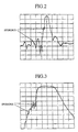
- Fig. 2 shows the transmission characteristic of the above-mentioned SAW filter measured over a 500 MHz frequency range from 692.5 to 1192.5 MHz with a 942.5 MHz center frequency. In Fig. 2 the ordinate is graduated to 0 dB in 5 dB increments.
- Fig. 3 shows the central portion of the Fig.
- Figs. 4 and 5 show its transmission characteristic. It will be seen that many spike-like spurious pulses are present particularly on the low-frequency side of the pass band in Fig. 4 but that the generation of such spurious pulses is appreciably suppressed in the Fig. 2 transmission characteristic.
- the value of M/L may preferably be 0.3 or more.
- spurious pulses are generated due to the high-order mode.
- the generation of spurious pulses is attributed to the reflection of waves of frequencies outside the pass band by the reflectors.
- the longitudinally coupled, dual mode SAW filter differs from the transversely-coupled, dual mode SAW filter in the mechanism of generation of spurious pulses, and hence it has a high degree of flexibility in designing the electrode pattern of the reflector. Accordingly, the electrodes need not be weighted along the sine curve as depicted in Fig. 20, but instead they can be weighted linearly.
- Fig. 12 is a diagrammatic representation of a second embodiment (Embodiment 2) of the present invention, which differs from Embodiment 1 in the shape of the right-hand reflector 12.
- the two reflectors are weighted so that they are point-symmetric to each other, whereas in Embodiment 2 the reflectors 8 and 12 are weighted so that they are point-symmetric with respect to a line perpendicular to the direction of propagation of surface acoustic waves.
- This structure also permits suppression of generation of spurious pulses as is the case with Embodiment 1.
- Fig. 14 depicts a magnified central portion of the measured characteristic.
- the numbers of electrodes of each IDT and each reflector are the same as in Embodiment 1.
- the spurious pulses can similarly be suppressed.
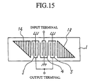
- Fig. 15 is a diagrammatic showing of a third embodiment (Embodiment 3) of the present invention.
- Fig. 16 shows a measured transmission characteristic of the longitudinally coupled, multi-mode SAW filter of this embodiment.
- Fig. 17 shows it magnified central portion of the measured characteristic.
- the spurious pulses can similarly be suppressed.
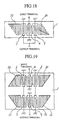
- Fig. 18 is a diagrammatic representation of a fourth embodiment (Embodiment 4) of the present invention.
- the electrodes of the IDTs and the reflectors are formed of aluminum (Al) and its alloys and are patterned into required form by wet or dry etching. In the case of wet etching, the electrodes are not clearly patterned because those portions in, for example, the reflectors 2 and 6 in Fig. 1 which are to be etched away are entirely surrounded by metal patterns.
- the Fig. 1 embodiment uses three bus bars to short opposite ends of metal grating electrodes of the reflectors 2 and 6.
- Embodiment 4 uses a single bus bar to short the metal grating electrodes of each of reflectors 20 and 24--this prevents each reflector from being entirely surrounded by metal patterns, and hence it provides a structure easy for wet etching.
- Fig. 19 is a diagrammatic showing of a fifth embodiment (Embodiment 5) of the present invention, which is a two-stage connection of 3-IDT-type longitudinally coupled, multi-mode SAW filters each having three IDTs and a reflector on either side of the IDT assembly.
- longitudinally coupled, multi-mode SAW filters having differently weighted reflectors generate spurious pulses of different shapes in the vicinity of the pass band.
- the electrodes of reflectors 26, 30 and 31, 35 of the two SAW filters in Fig. 19 are weighted differently from each other so that crests and troughs of spurious pulses in the two SAW filters cancel each other as much as possible.
Landscapes
- Physics & Mathematics (AREA)
- Acoustics & Sound (AREA)
- Surface Acoustic Wave Elements And Circuit Networks Thereof (AREA)
Abstract
In a longitudinally coupled multi-mode surface acoustic wave filter
which has an assembly of more than two interdigital transducers (IDTs) 3, 5
and 5 formed on a piezoelectric substrate 1 and reflectors 2 and 6 composed
of shorted grating electrodes 101 and 102 different in pitch from the IDTs, the
grating electrodes 101 and 102 are weighted so that their numbers vary
linearly with the position in the direction perpendicular to the direction of
propagation of surface acoustic waves.
Description
The present invention relates to a surface acoustic wave filter for use
in a high-frequency circuit of a mobile communication device typified, for
example, by a portable telephone or car telephone and, more particularly, to
an easy-to-manufacture surface acoustic wave filter that has an excellent
attenuation characteristic in the neighborhood of its pass band.
A resonator type surface acoustic wave (hereinafter referred to as
SAW) filter is provided with reflectors on both sides of each interdigital
transducer (IDT) to reflect surface acoustic waves, thereby generating
standing waves.
With the provision of such reflectors, sawtooth or spike-like spurious
pulses develop in the vicinity of the pass band--this is attributable to the
reflectors. The sizes and shapes of these spurious pulses depend on the
configuration of the SAW filter, such as the number of IDTs used and the IDT
spacing.
Further, in recent portable telephone or similar mobile communication
systems the necessity for effective use of available frequency has lessened the
space between transmitting and receiving frequency bands, that is, what is
called a transition bandwidth, and there is the growing demand for SAW
filters which provide increased transmission attenuation in the neighborhood
of the pass band in such mobile communication systems.
Fig. 20 depicts a transversely-coupled, dual mode SAW filter
disclosed in Japanese Patent Application Laid-Open Gazette No. 128519/91.
This SAW filter has two resonators 201 and 202 disposed on a piezoelectric
substrate (made principally of crystal) 200 across the direction of propagation
of surface acoustic waves. The resonators 201 and 202 have reflectors 206
to 209 on both sides of interdigital transducers (IDTs) 203 and 204, and are
excited in fundamental and second-order modes. Each reflector is graded or
weighted by a different number of electrodes arranged in the direction of
propagation of surface acoustic waves, thereby suppressing high-order modes
and hence providing an improved spurious characteristic.
Incidentally, since the electrodes of the reflectors 203 to 209 in Fig. 20
are weighted along a sine curve, the development of filters encounters much
difficulty, for example, in the design of electrode patterns, including
simulations and in the creation of data on electrode patterns for use in the
fabrication of photomasks.
It is therefore an object of the present invention to provide a SAW
filter that permits suppression or elimination of the afore-mentioned spurious
pulses to improve attenuation in the vicinity of the pass band and has an
easy-to-develop and fabricate structure.
According to the present invention, there is provided a
longitudinal-coupled SAW filter that has at least two interdigital transducers
formed over a piezoelectric substrate and reflectors disposed on both sides of
the interdigital transducers and in which the reflectors each comprise: a group
of electrodes graded so that their number linearly varies with their position in
the direction perpendicular to the direction of propagation of surface acoustic
waves; and bus bars shorting the electrodes.
Since the electrode groups of the reflectors are graded so that the
number of electrodes of each group varies with their position in the direction
perpendicular to the direction of propagation of surface acoustic waves, the
present invention allows ease in the design and development of the SAW filter,
and permits reduction of the spurious pulses and hence provide improved
attenuation in the vicinity of the pass band.
In order to describe the invention in more detail, the preferred
embodiments of the invention will now be described with reference to the
accompanying drawings.
Fig. 1 schematically illustrates a SAW filter according to a first
embodiment (Embodiment 1) of the present invention, which is a
longitudinally coupled multi-mode SAW filter in which three IDTs 3 to 5 are
arranged on a piezoelectric substrate (LiTaO3, LiNbO3) 1 capable of exciting
surface acoustic waves and reflectors 2 and 6 are disposed on both sides of the
IDTs 3 to 5. The two reflectors 2 and 6 each have grating electrodes
weighted into trapedoidal form. Surface acoustic waves propagate in the
direction indicated by X, and each reflector is weighted so that the number of
its electrodes varies linearly with the position in the Y-direction perpendicular
to the X-direction. For example, the number of electrodes of the reflector 6
is four at the farthest position and 10 at the nearest position in the Y-direction.
The reflector 5 have their electrodes 101 and 102 shorted at both ends by bus
bars 103, 104 and 105. The reflector 2 is point-symmetrical in construction
to the reflector 6. The reflectors 2 and 6 differ in the pitch of electrodes
from the IDTs 3 to 5. Reference character L denotes the length of the
reflector in the direction of propagation of surface acoustic waves, and M
denotes the length of the weighted or graded portion of the reflector in the
direction of propagation of surface acoustic waves.
To confirm the reflector weighting effect, the present inventors built a
prototype of a longitudinally coupled multi-mode SAW filter of the Fig. 1
structure in which: the IDTs 3 and 5 each had 22 electrodes; the IDT 4 had 31
electrodes; the reflectors 2 and 5 each had 146 electrodes; and M/L=0.5. Fig.
2 shows the transmission characteristic of the above-mentioned SAW filter
measured over a 500 MHz frequency range from 692.5 to 1192.5 MHz with a
942.5 MHz center frequency. In Fig. 2 the ordinate is graduated to 0 dB in 5
dB increments. Fig. 3 shows the central portion of the Fig. 2 transmission
characteristic magnified over a 100 MHz range in the direction of frequency,
the abscissa being graduated in terms of 3 dB. The same goes for the
ordinates and abscissas in the transmission characteristic diagrams and their
magnified versions described hereinafter.
For comparison with the SAW filter of this embodiment, the inventors
produced a longitudinally coupled multi-mode SAW filter of exactly the same
construction as that of the SAW filter of this embodiment except that M/L=0,
that is, the reflectors were not weighted and hence were rectangular in shape
as in the past. Figs. 4 and 5 show its transmission characteristic. It will be
seen that many spike-like spurious pulses are present particularly on the
low-frequency side of the pass band in Fig. 4 but that the generation of such
spurious pulses is appreciably suppressed in the Fig. 2 transmission
characteristic.
Figs. 6 to 11 show measured results of transmission characteristics of
SAW filters of exactly the same construction as that of the inventors'
prototyped SAW filter except that M/L=0.1, 0.3 and 0.7, respectively. Figs.
6, 8 and 10 show the transmission characteristics measured in the cases of
M/L=0.1, 0.3 and 0.7, respectively, and Figs. 7, 9 and 11 magnified versions
of central portion of the measured characteristics.
As can be seen from Figs. 6 to 11, the generation of spurious pulses
diminishes as in the case of Fig. 2, and since the weighted area of each
reflector increases with an increase in the value of M/L, the generation of
spurious pulses is suppressed accordingly; in particular, attenuation increases
toward the pass band.
To provide a sufficient attenuation in the neighborhood of the pass
band, the value of M/L may preferably be 0.3 or more.
In the transversely-coupled, dual mode SAW filter of Fig. 20, spurious
pulses are generated due to the high-order mode. In contrast thereto, in the
longitudinally coupled, dual mode SAW filter as proposed by the present
invention, the generation of spurious pulses is attributed to the reflection of
waves of frequencies outside the pass band by the reflectors. The
longitudinally coupled, dual mode SAW filter differs from the
transversely-coupled, dual mode SAW filter in the mechanism of generation
of spurious pulses, and hence it has a high degree of flexibility in designing
the electrode pattern of the reflector. Accordingly, the electrodes need not be
weighted along the sine curve as depicted in Fig. 20, but instead they can be
weighted linearly.
Fig. 12 is a diagrammatic representation of a second embodiment
(Embodiment 2) of the present invention, which differs from Embodiment 1
in the shape of the right-hand reflector 12. In Embodiment 1 the two
reflectors are weighted so that they are point-symmetric to each other,
whereas in Embodiment 2 the reflectors 8 and 12 are weighted so that they are
point-symmetric with respect to a line perpendicular to the direction of
propagation of surface acoustic waves. This structure also permits
suppression of generation of spurious pulses as is the case with Embodiment
1.
Fig. 13 shows a measured transmission characteristic of the
longitudinally coupled, multi-mode SAW filter according to this embodiment
with M/L=0.5. Fig. 14 depicts a magnified central portion of the measured
characteristic. The numbers of electrodes of each IDT and each reflector are
the same as in Embodiment 1.
From Fig. 13 it is evident that the structure of this embodiment
effectively suppresses the generation of spurious pulses. Further, it can be
seen that since the weighted reflector 12 differ in shape from the counterpart
in Fig. 2, spurious pulses also somewhat differ in shape although they are
suppressed to the same extent as in the Fig. 2 embodiment.
Moreover, even if the two reflectors are weighted as if they were
flipped vertically into trapezoidal form, the spurious pulses can similarly be
suppressed.
Fig. 15 is a diagrammatic showing of a third embodiment
(Embodiment 3) of the present invention. This is a modified form of
Embodiment 1, in which M/L=1 and consequently reflectors 14 and 18 are
weighted so that they are triangular.
Fig. 16 shows a measured transmission characteristic of the
longitudinally coupled, multi-mode SAW filter of this embodiment. Fig. 17
shows it magnified central portion of the measured characteristic. This SAW
filter is exactly identical in construction with Embodiment 1 except that
M/L=1 as mentioned above. From Fig. 16 it can be seen that since the
weighted area of each reflector is maximized by M/L=1, spurious pulses can
be suppressed more than in the case of M/L= 0.1 to 0.7.
Moreover, even if the two reflectors are weighted as if they were
flipped vertically into triangular form, the spurious pulses can similarly be
suppressed.
Fig. 18 is a diagrammatic representation of a fourth embodiment
(Embodiment 4) of the present invention. It is customary in the art that the
electrodes of the IDTs and the reflectors are formed of aluminum (Al) and its
alloys and are patterned into required form by wet or dry etching. In the
case of wet etching, the electrodes are not clearly patterned because those
portions in, for example, the reflectors 2 and 6 in Fig. 1 which are to be
etched away are entirely surrounded by metal patterns.
To avoid this, the Fig. 1 embodiment uses three bus bars to short
opposite ends of metal grating electrodes of the reflectors 2 and 6. On the
other hand, Embodiment 4 uses a single bus bar to short the metal grating
electrodes of each of reflectors 20 and 24--this prevents each reflector from
being entirely surrounded by metal patterns, and hence it provides a structure
easy for wet etching.
It is also apparent that even if the two reflectors on both sides of the
IDT assembly are both weighted into such a shape as indicated by 20 or 24,
an easy-to-wet-etch structure could similarly be obtained.
Moreover, it is evident that such easy-to-wet-etch structures could
similarly be obtained using one bus bar to short the metal grating electrodes
of each reflector in the embodiments of Figs. 12 and 15.
Fig. 19 is a diagrammatic showing of a fifth embodiment
(Embodiment 5) of the present invention, which is a two-stage connection of
3-IDT-type longitudinally coupled, multi-mode SAW filters each having three
IDTs and a reflector on either side of the IDT assembly. As previously
referred to in connection with Embodiment 2, longitudinally coupled,
multi-mode SAW filters having differently weighted reflectors generate
spurious pulses of different shapes in the vicinity of the pass band.
Accordingly, the electrodes of reflectors 26, 30 and 31, 35 of the two SAW
filters in Fig. 19 are weighted differently from each other so that crests and
troughs of spurious pulses in the two SAW filters cancel each other as much
as possible. With multi-stage connection of such 3-IDT-type longitudinally
coupled, multi-mode SAW filters, it is possible to further suppress the
generation of spurious pulses in the overall transmission characteristic.
The same results could be obtained by a multi-stage connection of
longitudinally coupled, multi-mode SAW filters having one or four or more
IDTs.
It will be apparent that many modifications and variations may be
effected without departing from the scope of the novel concepts of the present
invention.
Claims (3)
- A longitudinally coupled surface acoustic wave filter provided with at least two or more interdigital transducers formed over a piezoelectric substrate and reflectors disposed on both sides of said at least two interdigital transducers, wherein:said reflectors each have electrodes weighted so that the number of said electrodes varies linearly with the position in the direction perpendicular to the direction of propagation of surface acoustic waves, and bus bars for shoring said weighted electrodes.
- The longitudinally coupled surface acoustic wave filter according to claim 1, wherein said each reflector has one bus bar for shorting said electrodes.
- A longitudinally coupled surface acoustic wave filter comprising a multi-stage connection of said filter of claim 1.
Applications Claiming Priority (1)
| Application Number | Priority Date | Filing Date | Title |
|---|---|---|---|
| PCT/JP2000/002651 WO2001082480A1 (en) | 2000-04-24 | 2000-04-24 | Vertical coupling surface acoustic wave filter |
Publications (2)
| Publication Number | Publication Date |
|---|---|
| EP1195896A1 true EP1195896A1 (en) | 2002-04-10 |
| EP1195896A4 EP1195896A4 (en) | 2005-06-01 |
Family
ID=11735959
Family Applications (1)
| Application Number | Title | Priority Date | Filing Date |
|---|---|---|---|
| EP00917427A Withdrawn EP1195896A4 (en) | 2000-04-24 | 2000-04-24 | ACOUSTIC SURFACE WAVE FILTER WITH VERTICAL COUPLING |
Country Status (6)
| Country | Link |
|---|---|
| US (1) | US6650207B1 (en) |
| EP (1) | EP1195896A4 (en) |
| JP (1) | JP3512777B2 (en) |
| KR (1) | KR20020021384A (en) |
| CA (1) | CA2375596A1 (en) |
| WO (1) | WO2001082480A1 (en) |
Cited By (4)
| Publication number | Priority date | Publication date | Assignee | Title |
|---|---|---|---|---|
| WO2004066491A1 (en) * | 2003-01-20 | 2004-08-05 | Epcos Ag | Electrical component having a reduced substrate area |
| EP1453200A1 (en) * | 2003-02-28 | 2004-09-01 | Northrop Grumman Corporation | Dual track saw reflector filter using weighted reflective gratings |
| CN100355204C (en) * | 2003-01-24 | 2007-12-12 | 株式会社村田制作所 | Elastic surface wave device, communication device |
| CN101889392A (en) * | 2007-12-11 | 2010-11-17 | 株式会社村田制作所 | Surface wave devices and duplexers |
Families Citing this family (9)
| Publication number | Priority date | Publication date | Assignee | Title |
|---|---|---|---|---|
| DE10206376B4 (en) * | 2002-02-15 | 2012-10-25 | Epcos Ag | Resonator filter with improved close selection |
| JP2004166213A (en) * | 2002-09-20 | 2004-06-10 | Murata Mfg Co Ltd | Surface acoustic wave device, and communication apparatus |
| JP5039290B2 (en) * | 2005-08-25 | 2012-10-03 | 太陽誘電株式会社 | Filter and antenna duplexer |
| JP2011217420A (en) * | 2006-02-24 | 2011-10-27 | Panasonic Corp | Surface acoustic wave filter, antenna duplexer, high-frequency module using them, and communication apparatus |
| JP6625579B2 (en) * | 2017-03-21 | 2019-12-25 | 太陽誘電株式会社 | Elastic wave filter |
| US11502668B2 (en) | 2018-11-16 | 2022-11-15 | Skyworks Solutions, Inc. | Multi-mode surface acoustic wave filter with stepped acoustic reflectors |
| CN114268294B (en) * | 2022-03-03 | 2022-06-17 | 深圳新声半导体有限公司 | SAW device including hybrid weighting type reflection grating and hybrid weighting type reflection grating |
| CN119182373B (en) * | 2023-11-13 | 2025-10-21 | 上海馨欧集成微电有限公司 | A high-frequency acoustic wave resonator and a communication device using the same |
| CN119030497A (en) * | 2024-08-29 | 2024-11-26 | 浙江星曜半导体有限公司 | Surface acoustic wave resonator, filter and electronic device |
Family Cites Families (15)
| Publication number | Priority date | Publication date | Assignee | Title |
|---|---|---|---|---|
| JPS5693414A (en) * | 1979-12-27 | 1981-07-29 | Fujitsu Ltd | Elastic surface wave element |
| JPS57208719A (en) * | 1981-06-19 | 1982-12-21 | Hitachi Ltd | Surface acoustic wave device |
| GB2127249A (en) * | 1982-09-20 | 1984-04-04 | Philips Electronic Associated | Acoustic surface wave device |
| JPS59200519A (en) * | 1983-04-28 | 1984-11-13 | Toshiba Corp | Surface acoustic wave resonator |
| JPS614316A (en) * | 1984-06-19 | 1986-01-10 | Nec Corp | Two-port elastic surface wave resonator |
| JPH0666626B2 (en) * | 1985-06-07 | 1994-08-24 | 株式会社日立製作所 | Surface acoustic wave resonator |
| EP0224866B1 (en) * | 1985-12-05 | 1993-02-17 | Siemens Aktiengesellschaft | Surface acoustic wave circuit element |
| JPH03128519A (en) * | 1989-09-12 | 1991-05-31 | Seiko Epson Corp | Saw resonator and saw filter |
| JPH0440705A (en) * | 1990-06-06 | 1992-02-12 | Murata Mfg Co Ltd | Longitudinal double mode surface acoustic wave filter |
| JP3245442B2 (en) * | 1992-03-03 | 2002-01-15 | 株式会社日立国際電気 | Surface acoustic wave resonator |
| JPH0685597A (en) * | 1992-09-02 | 1994-03-25 | Mitsubishi Electric Corp | Saw device |
| JP3128519B2 (en) | 1996-11-06 | 2001-01-29 | リンナイ株式会社 | Temperature controller for combined hot water heating system |
| DE19744948C2 (en) * | 1997-10-10 | 1999-12-09 | Siemens Ag | Acoustic filter, especially surface wave filter |
| JP2000196399A (en) | 1998-12-25 | 2000-07-14 | Toyo Commun Equip Co Ltd | Surface acoustic wave filters and resonators |
| JP3321443B2 (en) | 1999-10-26 | 2002-09-03 | 東洋通信機株式会社 | Primary-tertiary longitudinally coupled dual-mode SAW filter |
-
2000
- 2000-04-24 CA CA002375596A patent/CA2375596A1/en not_active Abandoned
- 2000-04-24 WO PCT/JP2000/002651 patent/WO2001082480A1/en not_active Ceased
- 2000-04-24 KR KR1020017016495A patent/KR20020021384A/en not_active Ceased
- 2000-04-24 US US10/019,024 patent/US6650207B1/en not_active Expired - Fee Related
- 2000-04-24 EP EP00917427A patent/EP1195896A4/en not_active Withdrawn
- 2000-04-24 JP JP2001579452A patent/JP3512777B2/en not_active Expired - Fee Related
Cited By (9)
| Publication number | Priority date | Publication date | Assignee | Title |
|---|---|---|---|---|
| WO2004066491A1 (en) * | 2003-01-20 | 2004-08-05 | Epcos Ag | Electrical component having a reduced substrate area |
| US8022556B2 (en) | 2003-01-20 | 2011-09-20 | Epcos Ag | Electrical component having a reduced substrate area |
| CN100355204C (en) * | 2003-01-24 | 2007-12-12 | 株式会社村田制作所 | Elastic surface wave device, communication device |
| EP1443642A3 (en) * | 2003-01-24 | 2010-03-10 | Murata Manufacturing Co., Ltd. | Saw filter and communications device |
| EP1453200A1 (en) * | 2003-02-28 | 2004-09-01 | Northrop Grumman Corporation | Dual track saw reflector filter using weighted reflective gratings |
| CN101889392A (en) * | 2007-12-11 | 2010-11-17 | 株式会社村田制作所 | Surface wave devices and duplexers |
| US8169278B2 (en) | 2007-12-11 | 2012-05-01 | Murata Manufacturing Co., Ltd. | Surface acoustic wave device and duplexer |
| CN101889392B (en) * | 2007-12-11 | 2013-04-03 | 株式会社村田制作所 | Surface acoustic wave device and duplexer |
| EP2226935A4 (en) * | 2007-12-11 | 2013-08-21 | Murata Manufacturing Co | SURFACE ACOUSTIC WAVE DEVICE AND DUPLEXER |
Also Published As
| Publication number | Publication date |
|---|---|
| WO2001082480A1 (en) | 2001-11-01 |
| KR20020021384A (en) | 2002-03-20 |
| CA2375596A1 (en) | 2001-11-01 |
| EP1195896A4 (en) | 2005-06-01 |
| JP3512777B2 (en) | 2004-03-31 |
| US6650207B1 (en) | 2003-11-18 |
Similar Documents
| Publication | Publication Date | Title |
|---|---|---|
| EP0897218B1 (en) | Surface acoustic wave filter | |
| KR100290204B1 (en) | Multimode surface acoustic wave filter | |
| US6208224B1 (en) | Surface acoustic wave filter with parallel arm resonators having different resonant frequencies | |
| JP2010273382A (en) | Surface acoustic wave resonator and surface acoustic wave filter using the same | |
| US6650207B1 (en) | Longitudinally coupled surface acoustic wave filter with linearly weighted reflectors | |
| JPH08265087A (en) | Surface acoustic wave filter | |
| JP3001350B2 (en) | Surface acoustic wave filter | |
| JP3419339B2 (en) | Surface acoustic wave filters, duplexers, communication equipment | |
| KR100680675B1 (en) | Surface acoustic wave apparatus | |
| JP5695191B2 (en) | Acoustic wave devices and modules | |
| CN116318036B (en) | Surface acoustic wave resonators, surface acoustic wave filters and duplexers | |
| EP1770858A2 (en) | Surface acoustic wave apparatus | |
| JPWO2001082480A1 (en) | Longitudinal coupling surface acoustic wave filter | |
| JP3366477B2 (en) | Vertical composite quad mode SAW filter | |
| US6597261B2 (en) | Surface acoustic wave ladder filter using interdigital transducers not involving resonance | |
| JPH10261935A (en) | Surface acoustic wave element | |
| US6147574A (en) | Unidirectional surface acoustic wave transducer and transversal-type saw filter having the same | |
| US6812812B2 (en) | Longitudinally coupled surface acoustic wave resonator filter | |
| CN119543877B (en) | A temperature-compensated surface acoustic wave resonator and filter | |
| JP2005295202A (en) | Surface acoustic wave filter and duplexer | |
| JPH10261936A (en) | Surface acoustic wave filter | |
| JP2007124440A (en) | Surface acoustic wave element and surface acoustic wave device | |
| JP4548305B2 (en) | Dual-mode surface acoustic wave filter | |
| JPH08213869A (en) | Interdigital transducer type surface acoustic wave resonator | |
| JP2002232265A (en) | Surface acoustic wave filter |
Legal Events
| Date | Code | Title | Description |
|---|---|---|---|
| PUAI | Public reference made under article 153(3) epc to a published international application that has entered the european phase |
Free format text: ORIGINAL CODE: 0009012 |
|
| 17P | Request for examination filed |
Effective date: 20011224 |
|
| AK | Designated contracting states |
Kind code of ref document: A1 Designated state(s): AT BE CH CY DE DK ES FI FR GB GR IE IT LI LU MC NL PT SE |
|
| RBV | Designated contracting states (corrected) |
Designated state(s): DE FR GB IT |
|
| A4 | Supplementary search report drawn up and despatched |
Effective date: 20050415 |
|
| STAA | Information on the status of an ep patent application or granted ep patent |
Free format text: STATUS: THE APPLICATION HAS BEEN WITHDRAWN |
|
| 18W | Application withdrawn |
Effective date: 20050602 |