EP1195876A2 - Digital protective relay system - Google Patents
Digital protective relay system Download PDFInfo
- Publication number
- EP1195876A2 EP1195876A2 EP01123857A EP01123857A EP1195876A2 EP 1195876 A2 EP1195876 A2 EP 1195876A2 EP 01123857 A EP01123857 A EP 01123857A EP 01123857 A EP01123857 A EP 01123857A EP 1195876 A2 EP1195876 A2 EP 1195876A2
- Authority
- EP
- European Patent Office
- Prior art keywords
- protective relay
- sections
- relay device
- section
- sampling pulse
- Prior art date
- Legal status (The legal status is an assumption and is not a legal conclusion. Google has not performed a legal analysis and makes no representation as to the accuracy of the status listed.)
- Granted
Links
Images









Classifications
-
- H—ELECTRICITY
- H02—GENERATION; CONVERSION OR DISTRIBUTION OF ELECTRIC POWER
- H02H—EMERGENCY PROTECTIVE CIRCUIT ARRANGEMENTS
- H02H3/00—Emergency protective circuit arrangements for automatic disconnection directly responsive to an undesired change from normal electric working condition with or without subsequent reconnection ; integrated protection
- H02H3/02—Details
-
- H—ELECTRICITY
- H02—GENERATION; CONVERSION OR DISTRIBUTION OF ELECTRIC POWER
- H02H—EMERGENCY PROTECTIVE CIRCUIT ARRANGEMENTS
- H02H7/00—Emergency protective circuit arrangements specially adapted for specific types of electric machines or apparatus or for sectionalised protection of cable or line systems, and effecting automatic switching in the event of an undesired change from normal working conditions
- H02H7/26—Sectionalised protection of cable or line systems, e.g. for disconnecting a section on which a short-circuit, earth fault, or arc discharge has occured
- H02H7/261—Sectionalised protection of cable or line systems, e.g. for disconnecting a section on which a short-circuit, earth fault, or arc discharge has occured involving signal transmission between at least two stations
-
- H—ELECTRICITY
- H02—GENERATION; CONVERSION OR DISTRIBUTION OF ELECTRIC POWER
- H02H—EMERGENCY PROTECTIVE CIRCUIT ARRANGEMENTS
- H02H1/00—Details of emergency protective circuit arrangements
- H02H1/0061—Details of emergency protective circuit arrangements concerning transmission of signals
-
- H—ELECTRICITY
- H02—GENERATION; CONVERSION OR DISTRIBUTION OF ELECTRIC POWER
- H02H—EMERGENCY PROTECTIVE CIRCUIT ARRANGEMENTS
- H02H3/00—Emergency protective circuit arrangements for automatic disconnection directly responsive to an undesired change from normal electric working condition with or without subsequent reconnection ; integrated protection
- H02H3/26—Emergency protective circuit arrangements for automatic disconnection directly responsive to an undesired change from normal electric working condition with or without subsequent reconnection ; integrated protection responsive to difference between voltages or between currents; responsive to phase angle between voltages or between currents
- H02H3/28—Emergency protective circuit arrangements for automatic disconnection directly responsive to an undesired change from normal electric working condition with or without subsequent reconnection ; integrated protection responsive to difference between voltages or between currents; responsive to phase angle between voltages or between currents involving comparison of the voltage or current values at two spaced portions of a single system, e.g. at opposite ends of one line, at input and output of apparatus
Definitions
- the present invention relates to a protective relay for synchronizing the sampling of electrical quantity data at a plurality of terminals on an electric power system by using a Global Positioning System, referred to as GPS.
- GPS Global Positioning System
- a protective relay system in which electrical quantity data, such as electric current, is sampled at a plurality of positions or terminals in an electric power system, such as a power transmission system. Electrical quantity data in digital form obtained by the sampling is exchanged between the terminals and used for calculation for the purpose of providing a protective function for the electrical power system.
- the sampling at the respective terminals must be synchronized, whereby the time at which the electrical quantity data is sampled at the respective terminals must be made to coincide accurately. This ensures that electrical quantity data obtained by synchronous sampling (that is, simultaneous sampling) is used for the calculation.
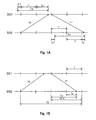
- Fig. 1A is time chart illustrating the exchange of synchronous signals between a main terminal SS1 (master terminal) and a secondary terminal SS2 (servant terminal) opposite to each other across a transmission line. That is, a sampling with a sampling frequency T is operated between terminals, and a sampling time deviation T exists.
- the terminal SS2 transmits a synchronous signal F0 (sampling synchronized flag) to the terminal SS1 with the electrical quantity data.
- the terminal SS1 measures the receiving timing Tm of the data having the synchronous signal F0 as transmitted from the terminal SS2 based on the sampling timing at the terminal SS1.
- the terminal SS1 transmits the receiving timing Tm and a synchronous signal F1 to the terminal SS2.
- the terminal SS2 also measures the receiving timing Ts of the data having the synchronous signal F1 as transmitted from the terminal SS1 based on the sampling timing at the terminal SS2.
- i represent an integer (i is equal to 1 in Fig. 1A), and j represents an integer (if Ts is less than Tm, j is equal to i+1, if Ts is Tm or more, j is equal to i.)
- Equation (3) is derived from equation (1) and (2).
- Ts is less than Tm
- (Ts +T) is approximately equal to Ts
- (j - i) ⁇ T in equation (3) may be disregarded.
- (j-i) ⁇ T is multiple of T.
- the equation (3) may be described in the manner as shown in equation (4). Accordingly, the sampling timing at each terminal becomes equal by shifting the sampling timing at the terminal SS2 so that T can be set equal to a substantially zero value.
- Fig. 1B is a time chart illustrating the exchange of synchronous signals between terminals SS1 and SS2. This time chart shows the sampling timing at each terminal is equal.
- the terminal SS2 measures the sampling frequency T0, which is the time difference between the time point in which the terminal SS2 receives the synchronous signal F0 (sampling synchronized flag) and the time point in which the terminal SS2 receives the synchronous signal F1 (sampling synchronized flag) in return.
- the transmission delay time Td is calculated in accordance with the equation (5) based on T0, Ts and T.
- Td T0/2 - T + Ts
- the delay time of the data transmitted from the terminal SS2 (the opposite terminal) to the sampling timing at the terminal SS1 can be determined.
- a protective relay calculation can be made at each terminal by using the sampling data obtained from the same sampling.
- the above sampling synchronizing method requires the addition of data for synchronizing into the transmitted data. Therefore, a first disadvantage of this method is that the transmission delay time to both directions on the transmission lines need to be same for establishing synchronous control between terminals.
- a second disadvantage of this method as above mentioned is that the rate of operation lowers because the loss of synchronism happens in response to the fluctuation of the transmission delay time even if the downstream and the upstream transmission delay time on the transmission lines are same.
- the present invention has been made in view of the above-mentioned circumstances and is intended to solve the above-mentioned problems.
- the object of the present invention is to provide a digital protective relay system in an electric power system, having two or more terminals being coupled to form a pair, and protective relay devices provided at each of the terminals.
- the system includes receiving sections that respectively are connected to the protective relay device, each receiving section receiving an electric wave from a satellite and outputting a fixed cycle pulse.
- the system also includes clock signal generating sections that respectively are set in each protective relay device, each clock signal generating sections generating a clock signal.
- the system further includes sampling pulse generating sections that respectively are set in each protective relay device, each sampling pulse generating section generating a sampling pulse with a fixed frequency in accordance with the clock signal.
- the system still further includes timing difference measurement sections that respectively are set in each protective relay device, each timing difference measurement section measuring a timing difference of the fixed cycle pulse and the sampling pulse.
- the system also includes correcting sections that respectively are set in each protective relay device, each correcting section correct a frequency of the sampling pulse from each sampling pulse generating section in accordance with the timing difference.
- the system further includes digital converting sections that respectively are set in each protective relay device, each digital converting section generating an electrical quantity data in digital form by sampling an electrical quantity of the electric power system in accordance with the sampling pulse of each sampling pulse generating section.
- the system still further includes transmitting sections that respectively are set in each protective relay device, each transmitting section transmitting and receiving the electrical quantity data between each protective relay device.
- the system also includes calculating sections that respectively are set in each protective relay device, each calculating section performing a calculation for a protective function by using the electrical quantity data obtained at each protective relay device.
- the system further includes outputting sections that respectively are set in each protective relay device, each outputting section outputting the result of the calculating section at each protective relay device.
- Fig. 1A and Fig. 1B are time charts illustrating the exchange of the synchronous signals between terminals.
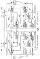
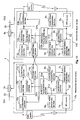
- Fig.2 is a diagram showing a first embodiment in accordance with the present invention.
- Fig. 3 is a time chart illustrating a principle of synchronization.
- Fig. 4 is a diagram showing a second embodiment in accordance with the present invention.
- Fig. 5 is a diagram showing a third embodiment in accordance with the present invention.
- Fig. 6 is a diagram showing a fourth embodiment in accordance with the present invention.
- Fig. 7 is a diagram showing a fifth embodiment in accordance with the present invention.
- Fig. 8 is a diagram showing a seventh embodiment in accordance with the present invention.
- Fig. 9 is a diagram showing an eighth embodiment in accordance with the present invention.
- Fig. 10 is a diagram showing a tenth embodiment in accordance with the present invention.
- Fig. 11 is a diagram showing an eleventh embodiment in accordance with the present invention.
- Fig. 12 is a graphic chart showing a twelfth embodiment in accordance with the present invention.
- Fig. 13 is a block diagram showing a thirteenth embodiment in accordance with the present invention.
- Fig. 14 is a block diagram showing a fourteenth embodiment in accordance with the present invention.
- Fig. 15 is a block diagram showing a fifteenth embodiment in accordance with the present invention.
- Fig. 16 is a block diagram showing a sixteenth embodiment in accordance with the present invention.
- Fig. 17 is a block diagram showing a seventeenth embodiment in accordance with the present invention.
- Fig. 18 is a block diagram showing an eighteenth embodiment in accordance with the present invention.
- Fig.2 shows the diagram showing a first embodiment in accordance with the present invention.
- a protective relay system protecting a transmission line 1 through a pair of protective relay devices (a protective relay device 14a and 14b), which is provided at a terminal SS1 and a terminal SS2 opposite to each other across the transmission line 1.
- a protective relay device 14a and 14b which is provided at a terminal SS1 and a terminal SS2 opposite to each other across the transmission line 1.
- current transformers 2a and 2b for detecting the current through the transmission line 1 and for adjusting the detected current for the protective relay device 14a and 14b, and circuit breakers 3a and 3b that are operative responsive to the protective relay device 14a and 14b.
- the protective relay device 14a and 14b respectively receive the currents from current transformer 2a and 2b, and periodically sample the currents and digitize them to obtain current data through A/D conversion sections 10a and 10b.
- the obtained electrical quantity data which is exchanged through a transmitting section 11a and 11b is used for a protective function calculation in a calculating section 12a and 12b.
- a result of the calculation is that the transmission line 1 is found to be in a state requiring disconnection, outputting sections 13a and 13b output trip signals to cause the tripping of the circuit breaker 3a and 3b.
- the time at which the electrical quantity data is sampled at the respective device 14a and 14b must be made to coincide accurately.
- a GPS (Global Positioning System) receiver 5a and 5b outputs a fixed cycle pulse S0 at the same timing, received from a GPS satellite 4.
- clock signal generating sections 6a and 6b outputs clock signals S1a and S1b, respectively. These clock signals S1a and S1b are asynchronous.
- the GPS system converts a time counted by an atomic clock (comprising an ultraprecise oscillator formed of cesium or rubidium), mounted on a satellite, to a time signal and transmits the signal from the satellite to a receiver station on the ground.
- a transmission time during which the signal is transmitted is measured on the basis of the difference between the time represented by the time signal received by the receiver station and the time when the signal is actually received.
- Timing difference measuring section 7a measures the timing difference of the fixed cycle pulse S0 and a sampling pulse S2a.
- Sampling pulse S2A is output by sampling pulse generating section 9a.
- a timing difference measuring section 7b measures the timing difference of the fixed cycle pulse S0 and a sampling pulse S2b.
- Sampling pulse S2B is output by sampling pulse generating section 9b.
- a correcting section 8a and 8b respectively correct the frequency of sampling pulse S2a and S2b so that the timing difference measured through timing difference measuring sections 7a and 7b is substantially zero.
- protective relay devices 14a and 14b which are the devices which are mutually independent, since asynchronous sampling pulse S2a and S2b serve as the same timing on the basis of the fixed cycle pulse S0, the synchronization between terminals is established.
- each device 14a and 14b can give the same counter value to the sampling data of the same time, if the counters CNa and CNb updated every sampling pulse S2a and S2b with the time as the starting point of the input of the fixed cycle pulse S0 are formed.
- this counter value when this counter value is transmitted with the electrical quantity data from an opposite terminal, a reception terminal reads this counter value. Namely, the electrical quantity data having the same counter value can be used for calculation for the purpose of the protective function. In addition, if the transmission delay time between the protective relay device 14a and 14b is less than a sampling cycle, it is not necessary to provide the above-mentioned counter.
- sampling timing can be made the same among plural protective relay device which operate independent from each other.
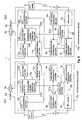
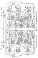
- Fig. 4 is a block diagram showing a second embodiment in accordance with the present invention.
- Fig. 4 the same elements as shown in Fig.2 are identified with the same reference numerals as used in Fig.2, and explanation is omitted for the sake of brevity.
- the difference between the first embodiment and this embodiment is the addition of a differential current operating sections 15a and 15b.
- the timing difference measuring section 7a and 7b and the correcting section 8a and 8b will not function properly or at all. Therefore, the synchronization will slip gradually by virtue of the deviation between clock signals from the clock signal generating section 6a and 6b.
- This embodiment is based on the principle that the vector sum of the current at both ends and the so-called differential current become equal to zero, when the synchronization between the protective relay device 14a and 14b is established in the state where there is no fault in a transmission line 1.
- the protective relay device 14a is used as a main terminal, and the protective relay device 14b as a secondary terminal.
- the sampling pulse S2b of the protective relay device 14b can follow the sampling pulse S2a of the protective relay device 14a, and can continue the synchronous establishment state between terminals.
- the ordinary difference current value calculated with the differential current operating section 15a and 15b is stored.
- the differential current operating section controls the sampling pulse width according to the difference of the differential current value and the present differential current value with which it had stored before the GPS receivers 5a and 5b stop outputting S0.
- the difference is used to correct the frequency of the clock signal S1b through the correcting section 8b so that the differential current value to which the present difference current value is recorded may be approximated.
- the sampling pulse which was synchronized between terminals, can be continued and outputted.
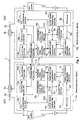
- Fig. 5 is a block diagram of a third embodiment in accordance with the present invention.
- the protective relay device 14a is used as a main terminal, and the protective relay device 14b as a secondary terminal.
- the frequency of the clock signal S1b is corrected through the correcting section 8b so that the phase difference of the current for which it obtained with a differential phase operating sections 16a and 16b may serve as approximately equal to 0.
- the sampling pulse S2b of the protective relay device 14b can follow the sampling pulse S2a of the protective relay device 14a, and can continue the synchronous establishment state between terminals.
- phase difference of current cannot be calculated. Therefore, when the current is less than a predetermined value, synchronization is not based on the phase difference of current, but rather the phase difference of voltage may be made to maintain synchronization. In addition, since phase difference has always occurred in the past in this case, correction will be performed so that it may become set to a value approximately equal to the ordinary phase difference.
- the sampling pulse when the GPS satellite does not output timing signals, or when the fixed cycle pulse from the GPS receiver is not outputted, the sampling pulse, which may be synchronized between terminals, can be continued and outputted.
- Fig. 6 is a block diagram of a fourth embodiment in accordance with the present invention.
- Fig. 6 the same elements as shown in Fig.2 are identified with the same reference numerals as used in Fig.2, and explanation is omitted for the sake of brevity.
- the difference between the first embodiment and this embodiment is the addition of receiving timing measuring sections 17a and 17b and a transmission delay time operating sections 18a and 18b between terminals.
- the receiving timing Tm and Ts is measured with the receiving timing measuring sections 17a and 17b.
- the transmission delay time Td is obtained by the transmission delay time operating sections 18a and 18b.
- the GPS satellite 4 when the GPS satellite 4 does not output timing signals, or when the fixed cycle pulse S0 is not outputted from the GPS receivers 5a and 5b, it switches to the sampling synchronous method by the above mentioned method, whereby the sampling pulse which may be synchronized between terminals can be continued and outputted even when the GPS system fails to output properly.
- Fig. 7 is a block diagram of a fifth embodiment in accordance with the present invention.
- Fig. 7 the same elements as shown in Fig.2 are identified with the same reference numerals as used in Fig.2, and explanation is omitted for the sake of brevity.
- the difference between the first embodiment and this embodiment is the addition of transmission signal receiving timing measuring sections 17a and 17b and transmission delay time operating sections 18a and 18b between terminals.
- a protective relay device 14a is used as a main terminal, and a protective relay device 14b as a secondary terminal. While the predetermined periodic pulse is output from a GPS receivers 5a and 5b, each device 14a and 14b calculates and records transmission delay time from the receiving timing that is measured. When the GPS satellite 4 does not output timing signals, or when the fixed cycle pulse S0 is not outputted from the GPS receivers 5a and 5b, the frequency of the clock signal S1b is corrected from the transmission delay time and the present data receiving timing which were stored, through the correcting section 8b.
- the sampling pulse S2b of the protective relay device 14b can synchronize with the sampling pulse S2a of the protective relay device 14a, and the synchronous establishment state between terminals can continue even when the GPS system temporarily fails to operate properly.
- the sampling pulse may still be synchronized between terminals and outputted.
- the sampling pulse may still be synchronized and outputted between terminals in the sampling synchronous continuation sections in the protective device 14a and 14b.
- the sixth embodiment has at least two or more of the sampling synchronous continuation sections described in each previously-described embodiment, and even if it is made to correct, complementing mutually, the same effect can be acquired.
- the current which flows on the transmission line is measured and used as a means of synchronous control even when the GPS system fails. That is, although neither the differential current nor the phase difference can be calculated when current is not flowing, through the fourth and the fifth embodiment which do not use current, synchronous control can be attained even when the GPS system fails.
- Fig. 8 is a block diagram of a seventh embodiment in accordance with the present invention.
- Fig.8 the same elements as shown in Fig.2 are identified with the same reference numerals as used in Fig.2, and explanation is omitted for the sake of brevity.
- the difference between the first embodiment and this embodiment is the addition of setting value input sections 19a and 19b and condition judging sections 20a and 20b.
- a marginal value as a threshold value, is beforehand inputted for various elements, such as the continuation time, difference current, and change of phase difference and the data receiving timing from the opposite terminal, at the setting value inputting sections 19a and 19b, taking into consideration the case that a protective relay device may operate incorrectly over time.
- the condition judging sections 20a and 20b judge that the simultaneity of the sampling timing between terminals has been lost, when an element mentioned above exceeds the corresponding marginal value, and they prevent the unwanted (e.g. incorrect) output from the output sections.
- the state of continuing and outputting a sampling pulse continues for a long time, when it changes into the state where differential current and phase difference may occur in response to a fault, and when receiving timing changes suddenly due to change of transmission delay time or the like, it can prevent a synchronous slip from arising between terminals.
- an eighth embodiment in accordance with the present will be explained.
- the following functions may be added to the protective relay device of each embodiment mentioned above.
- all the electrical quantity data acquired with two or more protective relay device is sampled to the same timing. Therefore, it is effective to operate to collect aforementioned amount of electrical data and to make a comparison study of the collected data and a new operation.
- a GPS receiver 5c separate from the protective relay device is provided in a different composition.
- the fixed cycle pulse S0 provided to two or more protective relay device from a same GPS receiver 5d can be applicable to each embodiment mentioned above.
- Fig. 11 is a block diagram of an eleventh embodiment in accordance with the present invention.
- Fig. 11 the same elements as shown in Fig.2 are identified with the same reference numerals as used in Fig.2, and explanation is omitted for the sake of brevity.
- the difference between the first embodiment and this embodiment is the addition of operating sections 12a1 and 12b2 and fixed cycle pulse detecting sections 22a and 22b.
- the state of the fixed cycle pulse S0 output from the GPS receivers 5a and 5b is monitored.
- operating sections 12a 12b will be switched to operating sections 12a1 and 12b1 having a sensitivity operating characteristic lower than those of the operating sections 12a and 12b.
- Fig. 12 shows the operating characteristic of the operating sections 12a and 12b and the operating sections 12a1 and 12b1.
- the horizontal axis signifies inflow current Ii and the vertical axis signifies outflow current Io.
- Itap signifies the minimum sensitivity determined from the minimum fault current.
- Iksc signifies the maximum outflow current, from which it is determined that an un-wanted operation corresponds to the zone above this, for preventing unwanted operation by current saturation on current transformers 2a and 2b.
- the small current region characteristic DF1 is calculated by the following equation through the operating sections 12a1 and 12b1.
- the ratio characteristic coefficient is (4/7). That is, as compared with the above-mentioned equation that applied the ratio characteristic coefficient (5/7), the operating zone is narrowed by using a smaller characteristic coefficient. Moreover, the minimum sensitivity setting value (Itap) may be changed to a different value such as (Itapx1.2), and the minimum sensitivity may be made lower as a result.
- Fig. 13 is a block diagram of a twelfth embodiment in accordance with the present invention.
- Fig. 13 the same elements as shown in Fig.9 are identified with the same reference numerals as used in Fig.9, and explanation is omitted for the sake of brevity.
- the difference between this embodiment and Fig. 9 is the addition of release inputting sections 32a and 32b, receiving timing measuring sections 17a and 17b, and timing difference operating sections 23a and 23b.
- the phase difference operating sections 16a and 16b described with respect to previous embodiments can replace the difference current operating sections 15a and 15b.
- the seventh embodiment when it is judged that the simultaneity of the sampling timing between each terminal was lost by the condition judging sections 20a and 20b, the unwanted output from the output sections is prevented. Unless the GPS signal is recovered and a fixed cycle pulse is obtained at this time, from the viewpoint of prevention of an unwanted operation, a safe control of the system to be protected may not occur based just on the lock of the output sections.
- the lock of output sections 13a can be canceled by condition judging sections 20a of the same terminal 14a by giving a release input to release inputting sections 32a, as shown in Fig. 14, in the transmission path state where a sampling synchronization can be performed using the related art above-mentioned synchronous system. Moreover, the lock of output section 13b can be canceled through the transmitting section 11a and 11b to the condition judgment section 20b of the other terminal (14b).
- Fig. 14 is a block diagram of a thirteenth embodiment in accordance with the present invention.
- Fig. 14 the same elements as shown in Fig.9 are identified with the same reference numerals as used in Fig.9, and explanation is omitted for the sake of brevity.
- the difference between this embodiment and Fig. 9 is the addition of receiving timing measuring sections 17a and 17b and timing difference operating sections 23a and 23b.
- the phase difference operating sections 16a and 16b described with respect to previous embodiments can replace the differential current operating sections 15a and 15b.
- Fig. 15 is a block diagram of a fourteenth embodiment in accordance with the present invention.
- Fig. 15 the same elements as shown in Fig.14 are identified with the same reference numerals as used in Fig.14, and explanation is omitted for the sake of brevity.
- the difference between this embodiment and Fig.14 is the addition of timing difference sudden change detection sections 24a and 24b. It operates by applying the sampling synchronization using the above-mentioned synchronous method by the timing differential measuring sections 23a and 23b under the state where the GPS signal is absent.
- Transmission delay time changes with changes of a transmission path.
- a measurement result to which the sampling synchronous error, which corresponds to half of the difference between rise-transmission delay time and fall-transmission delay time, is obtained as an output from the timing difference measuring sections 23a and 23b.
- the case of becoming not equivalent also has the transmission rise and fall delay time of only the time lag corresponding to the time which switches each transmission path from downstream to upstream. For example, the case where the transmission delay rise and fall time is respectively operated in 1ms is considered below.
- operation can be continued, without locking a current differential relay, though the transmission rise and fall delay time does not becomes equivalent, while a GPS signal is lost, by applying the sampling synchronization by the mentioned related method and above-mentioned synchronous system operated temporarily. As a result, improvement in the rate of employment can be achieved.
- Fig. 16 is a block diagram of a fifteenth embodiment in accordance with the present invention.
- Fig. 16 the same elements as shown in Fig.6 are identified with the same reference numerals as used in Fig.16, and explanation is omitted for the sake of brevity.
- the difference between this embodiment and Fig.6 is the addition of positive-phase voltage operating sections 25a and 25b.
- the positive-phase voltage operating sections 25a and 25b calculate positive-phase voltage from the voltage data obtained from analog/digital conversion sections 10a and 10b.
- the positive voltage is transmitted and received between terminals through the transmitting sections 11a and 11b.
- the phase differential operating sections 16a and 16b calculate phase difference based on the positive voltage, which they receive.
- the phase difference by voltage data can be obtained.
- the sampling pulse which enables synchronization between terminals can be maintained and outputted.
- Fig. 17 is a block of a sixteenth embodiment in accordance with the present invention.
- Fig. 17 the same elements as shown in Fig.6 are identified with the same reference numerals as used in Fig.6, and explanation is omitted for the sake of brevity.
- the difference between this embodiment and Fig. 6 is the addition of charge current setting sections 26a and 26b, charge current calculating sections 27a and 27b, and charge current removal sections 28a and 28b.
- the charging current setting sections 26a and 26b provide and hold from the exterior the amount of charging current Icn, which flows at the time of rated voltage Vn.
- An electric power system can determine the charge current Ic which actually flows by the following equation, using voltage data V obtained from the analog / digital conversion sections 10a and 10b.
- Ic (V/Vn) * Icn
- the charging current removal sections 28a and 28b remove a charging current ingredient from current data I obtained from the analog/digital conversion sections 10a and 10b based on the charging current Ic inputted.
- the phase differential operating sections 16a and 16b calculate the phase difference that removes the error by charge current.
- the protective system can determine current phase difference, without being influenced by charge current. As a result, the sampling pulse which enables the synchronization between terminals can be maintained and outputted.
- Fig. 18 is a block diagram of a seventh embodiment in accordance with the present invention.
- Fig. 18 the same elements as shown in Fig.16 are identified with the same reference numerals as used in Fig.16, and explanation is omitted for the sake of brevity.
- the difference between this embodiment and Fig. 16 is the addition of current level judging sections 29a and 29b and phase difference operation input change sections 30a and 30b.
- current level judging sections 29a and 29b When voltage data is used for calculation of phase difference, the phases lag by the flowing current, which causes a problem.
- current data when current data is used, when there is little power flow, insufficient current data is obtained, thereby creating a problem.
- the current level judging sections 29a and 29b are provided. That is, when the amplitude of current is small, the phase differential operation input change sections 30a and 30b are controlled to perform phase differential operation using voltage data. Moreover, when the amplitude of current is large, the phase differential operation inputting sections 30a and 30b are controlled to use current data.
- the criterion of amplitude size is determined by the size of the absolute value of analog data through the A/D conversion.
- this embodiment when the GPS satellite does not output timing signals and the fixed cycle pulse from the above-mentioned GPS receiver is not outputted, this embodiment is not concerned with the size of the current, but instead it obtains the phase difference. As a result, the sampling pulse that enables synchronization between terminals can be maintained and outputted.
- the embodiment mentioned above rectifies the frequency of the concerned sampling pulse in timing difference measuring sections based on the timing difference of the fixed cycle pulse output from the GPS receiver, and the sampling pulse output from sampling pulse generating sections.
- Clock signal S1a and S1b of clock signal generating sections may be used instead of sampling pulse S2a and S2b output from sampling pulse generating sections. In that case, a timing difference is calculated, and the same effect as the above-mentioned embodiment can be acquired even if it corrects the frequency of sampling pulse S2a and S2b based on the timing difference concerned.
Landscapes
- Engineering & Computer Science (AREA)
- Power Engineering (AREA)
- Physics & Mathematics (AREA)
- Electromagnetism (AREA)
- Emergency Protection Circuit Devices (AREA)
- Synchronisation In Digital Transmission Systems (AREA)
- Position Fixing By Use Of Radio Waves (AREA)
Abstract
Description
Moreover, the minimum sensitivity setting value (Itap) may be changed to a different value such as (Itapx1.2), and the minimum sensitivity may be made lower as a result.
Ic = (V/Vn) * Icn
Claims (10)
- A digital protective relay system in an electric power system, having
two or more terminals (SS1, SS2) being coupled to form a pair, and protective relay devices (14a, 14b) provided at each of the terminals (SS1, SS2), comprising:receiving sections (5a, 5b) that respectively are connected to the protective relay device, each receiving section receiving an electric wave from a satellite (4) and outputting a fixed cycle pulse (S0);clock signal generating sections (6a, 6b) that respectively are set in each protective relay device(14a, 14b), each of the clock signal generating sections (6a, 6b) generating a clock signal (S1a, S1b);sampling pulse generating sections (9a, 9b) that respectively are set in each protective relay device(14a, 14b) each sampling pulse generating section (9a, 9b) generating a sampling pulse (S2a, S2b) with a fixed frequency in accordance with the clock signal (S1a, S1b);timing difference measurement sections (7a, 7b) that respectively are set in each protective relay device (14a, 14b), each timing difference measurement section (7a, 7b) measuring a timing difference of the fixed cycle pulse (S0) and the sampling pulse (S2a, S2b);correcting sections (8a, 8b) that respectively are set in each protective relay device (14a, 14b), each correcting section (8a, 8b) correct a frequency of the sampling pulse (S2a, S2b) from each sampling pulse generating section (9a, 9b) in accordance with the timing difference;digital converting sections (10a, 10b) that respectively are set in each protective relay device (14a, 14b), each digital converting section (10a, 10b) generating an electrical quantity data in digital form by sampling an electrical quantity of the electric power system in accordance with the sampling pulse (S2a, S2b)of each sampling pulse generating section (9a, 9b)transmitting sections (11a, 11b) that respectively are set in each protective relay device (14a, 14b), each transmitting section (11a, 11b) transmitting and receiving the electrical quantity data between each protective relay device (14a, 14b);calculating sections (12a, 12b) that respectively are set in each protective relay device (14a, 14b) each calculating section performing a calculation for a protective function by using the electrical quantity data obtained at each protective relay device (14a, 14b); andoutputting sections (13a, 13b) that respectively are set in each protective relay device (14a, 14b), each outputting section (13a, 13b) outputting the result of the calculating section at each protective relay device (14a, 14b). - The digital protective relay system according to claim 1, wherein the two or more terminals are communicatively coupled to each other by way of a transmission line.
- The digital protective relay system according to claim 1 or 2, wherein the electric wave output by the satellite is a GPS signal.
- The digital protective relay system according to any of claims 1 to 3, wherein the operating sensitivity operating characteristic of the protective function is made lower when the GPS satellite does not output timing signals, or when the fixed cycle pulse is not output from the GPS receiving sections.
- The digital protective relay system according to any of claims 1 to 4, further comprising:differential electrical data operating sections (15a, 15b, 16a, 16b) that respectively are connected to the protective relay device, each differential electrical data operating section calculating the differential electrical data at each of the terminals, said correcting sections correcting frequency of each clock signal by said differential electrical data when the GPS satellite does not output timing signals, or when the fixed cycle pulse is not output from the GPS receiving sections.
- The digital protective relay system according to any of claims 1 to 6, further comprising:device, each of the correcting sections correcting a timing slip between terminals by said transmission delay time.receiving timing measuring sections that respectively are connected to the protective relay device, each receiving timing measuring section measuring a transmission receive time;transmission delay time operating sections that respectively are connected to the protective relay device, each transmission delay time operating section obtaining the transmission delay time; andcorrecting sections that respectively are connected to the protective relay
- The digital protective relay system according to claim 5 or 6, further
comprising:condition judging sections that respectively are connected to the protective relay device, each condition judging section preventing the result of the calculating section from said outputting section when a predetermined condition is established, said predetermined condition being determined by an unwanted operation characteristic. - The digital protective relay system according to claim 7, wherein the
condition judging sections release the result of the calculating section from said outputting section when the timing difference data is determined to be within the prescribed limits and the electrical data is determined to be within the prescribed limits after preventing the result of the calculating. - The digital protective relay system according to claim 7 or 8, wherein the correcting sections stop correcting a frequency of the sampling pulse from each sampling pulse generating section in accordance with the timing difference when the transmission delay time changes with changes of a transmission path.
- A digital protective relay system in an electric power system, having two or more terminals being coupled to form a pair, and protective relay devices provided at each of the terminals, comprising:device, each receiving section receiving an electric wave from a satellite and outputting a fixed cycle pulse;receiving sections that respectively are connected to the protective relayprotective relay device, each timing difference measurement section measuring a timing difference of the fixed cycle pulse and the sampling pulse;clock signal generating sections that respectively are set in each protective relay device, each clock signal generating section generating a clock signal;sampling pulse generating sections that respectively are set in each protective relay device, each sampling pulse generating section generating a sampling pulse with a fixed frequency in accordance with the clock signal;timing difference measurement sections that respectively are set in eachcorrecting sections that respectively are set in each protective relay device, each correcting section correct a frequency of the sampling pulse from each sampling pulse generating section in accordance with the timing difference, wherein the timing difference is set an approximately zero value in said two or more terminals in order to obtain substantially synchronized sampling of an electrical parameter by said two or more terminals.
Applications Claiming Priority (2)
| Application Number | Priority Date | Filing Date | Title |
|---|---|---|---|
| JP2000307227 | 2000-10-06 | ||
| JP2000307227 | 2000-10-06 |
Publications (3)
| Publication Number | Publication Date |
|---|---|
| EP1195876A2 true EP1195876A2 (en) | 2002-04-10 |
| EP1195876A3 EP1195876A3 (en) | 2003-09-10 |
| EP1195876B1 EP1195876B1 (en) | 2007-04-18 |
Family
ID=18787773
Family Applications (1)
| Application Number | Title | Priority Date | Filing Date |
|---|---|---|---|
| EP01123857A Expired - Lifetime EP1195876B1 (en) | 2000-10-06 | 2001-10-05 | Digital protective relay system |
Country Status (6)
| Country | Link |
|---|---|
| US (1) | US6678134B2 (en) |
| EP (1) | EP1195876B1 (en) |
| JP (1) | JP5254157B2 (en) |
| KR (1) | KR100465944B1 (en) |
| CN (3) | CN101394077B (en) |
| DE (1) | DE60127916T2 (en) |
Cited By (7)
| Publication number | Priority date | Publication date | Assignee | Title |
|---|---|---|---|---|
| WO2008134994A1 (en) * | 2007-05-03 | 2008-11-13 | Siemens Aktiengesellschaft | Protective arrangement for an energy supply system having a bus bar, infeed branch, and shunt |
| WO2009012809A1 (en) * | 2007-07-23 | 2009-01-29 | Abb Technology Ag | Method and protection device for a power network accounting for route switching in a telecommunication network |
| RU2425437C1 (en) * | 2007-07-23 | 2011-07-27 | Абб Текнолоджи Аг | Method and protective device to compute electric network as route switches in long-distance network |
| GB2486684A (en) * | 2010-12-20 | 2012-06-27 | Mitsubishi Electric Corp | Sampling synchronization method for digital protective relaying system |
| EP2256891A4 (en) * | 2008-03-18 | 2012-12-12 | Toshiba Kk | Digital protection relay device and data transmission device for digital protection relay device |
| US8462476B2 (en) | 2008-06-02 | 2013-06-11 | Areva T&D Protection & Controle | Method and apparatus for providing differential protection for an electrical link in a medium, high, or very high voltage network |
| CN117277584A (en) * | 2023-11-17 | 2023-12-22 | 国网江苏省电力有限公司无锡供电分公司 | Multi-terminal electrical quantity protection synchronization method and system integrating electrical quantity and clock information |
Families Citing this family (41)
| Publication number | Priority date | Publication date | Assignee | Title |
|---|---|---|---|---|
| SE524670C2 (en) * | 2003-01-30 | 2004-09-14 | Abb Ab | A power balancing device and method |
| US7126800B2 (en) * | 2003-07-11 | 2006-10-24 | General Electric Company | Method and system for communications channel delay asymmetry compensation using global positioning systems |
| US7272201B2 (en) * | 2003-08-20 | 2007-09-18 | Schweitzer Engineering Laboratories, Inc. | System for synchronous sampling and time-of-day clocking using an encoded time signal |
| US7230809B2 (en) * | 2004-06-21 | 2007-06-12 | Schweitzer Engineering Laboratories, Inc. | System for checking synchronization of AC voltage sources before closing a power circuit breaker |
| US7398411B2 (en) * | 2005-05-12 | 2008-07-08 | Schweitzer Engineering Laboratories, Inc. | Self-calibrating time code generator |
| JP2008079367A (en) * | 2006-09-19 | 2008-04-03 | Toshiba Corp | Protective relay device |
| US7899619B2 (en) * | 2006-10-18 | 2011-03-01 | Schweitzer Engineering Laboratories, Inc. | Apparatus and method for transmitting information using an IRIG-B waveform generated by an intelligent electronic device |
| US20100254225A1 (en) * | 2009-04-03 | 2010-10-07 | Schweitzer Iii Edmund O | Fault tolerant time synchronization |
| JP2010279235A (en) * | 2009-06-01 | 2010-12-09 | Mitsubishi Electric Corp | Current differential relay |
| US8351433B2 (en) * | 2009-09-18 | 2013-01-08 | Schweitzer Engineering Laboratories Inc | Intelligent electronic device with segregated real-time ethernet |
| US8867345B2 (en) * | 2009-09-18 | 2014-10-21 | Schweitzer Engineering Laboratories, Inc. | Intelligent electronic device with segregated real-time ethernet |
| CN101752906B (en) * | 2009-12-17 | 2012-02-01 | 宁波兴邦电器有限公司 | High-voltage switch intelligent control system and control method thereof |
| PL2533388T3 (en) * | 2010-02-03 | 2017-03-31 | Hitachi, Ltd. | Digital protection control system and digital protection control apparatus |
| JP5457230B2 (en) * | 2010-03-05 | 2014-04-02 | 株式会社日立製作所 | Protection relay device and current differential protection relay device |
| JP5475551B2 (en) * | 2010-05-28 | 2014-04-16 | 株式会社東芝 | Protective relay device |
| US8812256B2 (en) | 2011-01-12 | 2014-08-19 | Schweitzer Engineering Laboratories, Inc. | System and apparatus for measuring the accuracy of a backup time source |
| WO2012132089A1 (en) * | 2011-03-25 | 2012-10-04 | 日本電気株式会社 | Synchronization device and synchronization method |
| WO2014002191A1 (en) | 2012-06-26 | 2014-01-03 | 三菱電機株式会社 | Current differential relay |
| ES2572956T3 (en) * | 2012-07-31 | 2016-06-03 | Abb Research Ltd. | Synchronization of clocks for differential line protection |
| JP2014054063A (en) | 2012-09-06 | 2014-03-20 | Toshiba Corp | Current differential relay system and current differential relay |
| CN102856981B (en) * | 2012-09-13 | 2015-04-22 | 北京四方继保自动化股份有限公司 | Station-area protection and control device with protection and control functions in converting station |
| CN102879734B (en) * | 2012-09-26 | 2015-06-17 | 宁夏电力公司电力科学研究院 | Method for testing time delay of on-off action of intelligent transformer substation |
| US9324122B2 (en) | 2012-10-19 | 2016-04-26 | Schweitzer Engineering Laboratories, Inc. | Voting scheme for time alignment |
| US8963558B2 (en) | 2012-10-31 | 2015-02-24 | General Electric Company | Current differential protection |
| US9300591B2 (en) | 2013-01-28 | 2016-03-29 | Schweitzer Engineering Laboratories, Inc. | Network device |
| US9270109B2 (en) | 2013-03-15 | 2016-02-23 | Schweitzer Engineering Laboratories, Inc. | Exchange of messages between devices in an electrical power system |
| US9065763B2 (en) | 2013-03-15 | 2015-06-23 | Schweitzer Engineering Laboratories, Inc. | Transmission of data over a low-bandwidth communication channel |
| US9620955B2 (en) | 2013-03-15 | 2017-04-11 | Schweitzer Engineering Laboratories, Inc. | Systems and methods for communicating data state change information between devices in an electrical power system |
| US9166876B2 (en) | 2013-04-25 | 2015-10-20 | Powercomm Solutions, Llc | Power communications monitor for power line carrier and audio tone communication systems |
| CN103676890A (en) * | 2013-12-18 | 2014-03-26 | 江苏方天电力技术有限公司 | Automatic calibrating device of comprehensive protection system |
| WO2016072038A1 (en) * | 2014-11-05 | 2016-05-12 | 日本電気株式会社 | Communication system, time synchronization method, and radio relay device |
| CN104901291A (en) * | 2015-05-29 | 2015-09-09 | 国电南瑞科技股份有限公司 | Intelligent fiber differential protection synchronization method based on Beidou time service |
| CN104977546B (en) * | 2015-06-29 | 2018-01-16 | 广东电网有限责任公司江门供电局 | A kind of Secondary Direct Electrical Resources towards transformer station lose method of discrimination |
| US20170085357A1 (en) * | 2015-07-17 | 2017-03-23 | Ful Spectrum Inc. | Devices, systems, and methods for synchronization of broadband wireless communication systems |
| US9967135B2 (en) | 2016-03-29 | 2018-05-08 | Schweitzer Engineering Laboratories, Inc. | Communication link monitoring and failover |
| US10819727B2 (en) | 2018-10-15 | 2020-10-27 | Schweitzer Engineering Laboratories, Inc. | Detecting and deterring network attacks |
| US11099238B2 (en) | 2019-03-27 | 2021-08-24 | General Electric Company | Distributed control modules with built-in tests and control-preserving fault responses |
| US11522358B2 (en) | 2020-05-18 | 2022-12-06 | Schweitzer Engineering Laboratories, Inc. | Isolation of protective functions in electrical power systems |
| US11862958B2 (en) | 2021-10-04 | 2024-01-02 | Schweitzer Engineering Laboratories, Inc. | Isolation of protection functions in electrical power systems during startup |
| US12105490B2 (en) | 2021-10-04 | 2024-10-01 | Schweitzer Engineering Laboratories, Inc. | Isolation of protection functions in electrical power systems |
| US12498938B2 (en) | 2021-11-10 | 2025-12-16 | Schweitzer Engineering Laboratories, Inc. | Basic input/output system (BIOS) boot check |
Family Cites Families (14)
| Publication number | Priority date | Publication date | Assignee | Title |
|---|---|---|---|---|
| JPS5246457A (en) * | 1975-10-13 | 1977-04-13 | Tokyo Electric Power Co Inc:The | Carrier protective relay device |
| JPS52129946A (en) * | 1976-04-23 | 1977-10-31 | Mitsubishi Electric Corp | Signal synchronizer |
| JPS5875419A (en) | 1981-10-29 | 1983-05-07 | 株式会社東芝 | Sampling time synchronizing device |
| JPS6039310A (en) * | 1983-08-12 | 1985-03-01 | 株式会社東芝 | Sampling synchronizing method |
| JPS648821A (en) * | 1987-06-30 | 1989-01-12 | Toshiba Corp | Differential relay |
| JP2735359B2 (en) * | 1990-05-08 | 1998-04-02 | 株式会社東芝 | Sampling synchronizer |
| JP3686430B2 (en) * | 1993-10-19 | 2005-08-24 | 東北電力株式会社 | Transmission line surge identification and orientation system |
| US5576625A (en) * | 1994-02-07 | 1996-11-19 | Kabushiki Kaisha Toshiba | Test method and apparatus for testing a protective relay system |
| JPH0837724A (en) * | 1994-07-22 | 1996-02-06 | Fuji Facom Corp | Sampling synchronization control method for analog data |
| JP3718977B2 (en) * | 1997-12-25 | 2005-11-24 | 株式会社明電舎 | Sampling synchronization method |
| JP3808624B2 (en) * | 1998-04-21 | 2006-08-16 | 株式会社東芝 | System protection relay device |
| JP2000092691A (en) * | 1998-09-07 | 2000-03-31 | Toshiba Corp | Digital type transmission line protection relay |
| KR20000046903A (en) * | 1998-12-31 | 2000-07-25 | 이종수 | Device and method for transmitting and receiving multi-terminal electric power line using global positioning system |
| JP2000228821A (en) * | 1999-02-08 | 2000-08-15 | Meidensha Corp | Optical pcm current differential relay system |
-
2001
- 2001-10-05 DE DE60127916T patent/DE60127916T2/en not_active Expired - Lifetime
- 2001-10-05 US US09/971,060 patent/US6678134B2/en not_active Expired - Lifetime
- 2001-10-05 KR KR10-2001-0061469A patent/KR100465944B1/en not_active Expired - Fee Related
- 2001-10-05 EP EP01123857A patent/EP1195876B1/en not_active Expired - Lifetime
- 2001-10-08 CN CN2008101710002A patent/CN101394077B/en not_active Expired - Fee Related
- 2001-10-08 CN CNB011354496A patent/CN100514784C/en not_active Expired - Fee Related
- 2001-10-08 CN CN2008101708017A patent/CN101394076B/en not_active Expired - Fee Related
-
2009
- 2009-08-26 JP JP2009195713A patent/JP5254157B2/en not_active Expired - Fee Related
Cited By (12)
| Publication number | Priority date | Publication date | Assignee | Title |
|---|---|---|---|---|
| WO2008134994A1 (en) * | 2007-05-03 | 2008-11-13 | Siemens Aktiengesellschaft | Protective arrangement for an energy supply system having a bus bar, infeed branch, and shunt |
| WO2009012809A1 (en) * | 2007-07-23 | 2009-01-29 | Abb Technology Ag | Method and protection device for a power network accounting for route switching in a telecommunication network |
| RU2425437C1 (en) * | 2007-07-23 | 2011-07-27 | Абб Текнолоджи Аг | Method and protective device to compute electric network as route switches in long-distance network |
| US8381008B2 (en) | 2007-07-23 | 2013-02-19 | Abb Technology Ag | Method and protection device for a power network accounting for route switching in a telecommunication network |
| CN101755372B (en) * | 2007-07-23 | 2013-04-24 | Abb技术有限公司 | Method and protection device for a power network accounting for route switching in a telecommunication network |
| EP2256891A4 (en) * | 2008-03-18 | 2012-12-12 | Toshiba Kk | Digital protection relay device and data transmission device for digital protection relay device |
| US8396098B2 (en) | 2008-03-18 | 2013-03-12 | Kabushiki Kaisha Toshiba | Digital protective relay device and data transmission device for the same |
| US8462476B2 (en) | 2008-06-02 | 2013-06-11 | Areva T&D Protection & Controle | Method and apparatus for providing differential protection for an electrical link in a medium, high, or very high voltage network |
| GB2486684A (en) * | 2010-12-20 | 2012-06-27 | Mitsubishi Electric Corp | Sampling synchronization method for digital protective relaying system |
| GB2486684B (en) * | 2010-12-20 | 2015-11-11 | Mitsubishi Electric Corp | Digital Protective Relaying System and Sampling Synchronization Method for Digital Protective Relaying System |
| CN117277584A (en) * | 2023-11-17 | 2023-12-22 | 国网江苏省电力有限公司无锡供电分公司 | Multi-terminal electrical quantity protection synchronization method and system integrating electrical quantity and clock information |
| CN117277584B (en) * | 2023-11-17 | 2024-02-02 | 国网江苏省电力有限公司无锡供电分公司 | Multi-terminal electric quantity protection synchronization method and system integrating electric quantity and clock information |
Also Published As
| Publication number | Publication date |
|---|---|
| CN101394077A (en) | 2009-03-25 |
| DE60127916D1 (en) | 2007-05-31 |
| KR100465944B1 (en) | 2005-01-13 |
| EP1195876A3 (en) | 2003-09-10 |
| US6678134B2 (en) | 2004-01-13 |
| DE60127916T2 (en) | 2008-01-17 |
| KR20020027273A (en) | 2002-04-13 |
| CN101394077B (en) | 2011-01-12 |
| CN101394076A (en) | 2009-03-25 |
| CN1348243A (en) | 2002-05-08 |
| JP2009284758A (en) | 2009-12-03 |
| EP1195876B1 (en) | 2007-04-18 |
| CN101394076B (en) | 2011-10-05 |
| US20020057544A1 (en) | 2002-05-16 |
| CN100514784C (en) | 2009-07-15 |
| JP5254157B2 (en) | 2013-08-07 |
Similar Documents
| Publication | Publication Date | Title |
|---|---|---|
| EP1195876B1 (en) | Digital protective relay system | |
| US11258249B2 (en) | Primary and system protection for an electric power delivery system | |
| EP1708330B1 (en) | Protective relay system | |
| EP1416603A1 (en) | Protection of an electric power transmission network | |
| US11482855B2 (en) | Electrical protection system for detection and isolation of faults in power distribution using synchronized voltage measurements and a method of its application | |
| JP5507025B1 (en) | Current differential relay | |
| US11114892B2 (en) | Electric power system transducer failure monitor and measurement recovery | |
| US8462476B2 (en) | Method and apparatus for providing differential protection for an electrical link in a medium, high, or very high voltage network | |
| AU2021213406B2 (en) | Time synchronization between IEDs of different substations | |
| WO2009012809A1 (en) | Method and protection device for a power network accounting for route switching in a telecommunication network | |
| CN100426616C (en) | Protective relay device | |
| Antonova et al. | Analysis of protection scheme dependencies on communications | |
| JP6832672B2 (en) | System stabilization system | |
| Saygin et al. | A primer on pilot protection with digital relays | |
| Kasztenny et al. | Fallback algorithms for line current differential protection applied with asymmetrical channels upon the loss of time reference | |
| JPH06105451A (en) | Track protection relay device |
Legal Events
| Date | Code | Title | Description |
|---|---|---|---|
| PUAI | Public reference made under article 153(3) epc to a published international application that has entered the european phase |
Free format text: ORIGINAL CODE: 0009012 |
|
| 17P | Request for examination filed |
Effective date: 20011005 |
|
| AK | Designated contracting states |
Kind code of ref document: A2 Designated state(s): AT BE CH CY DE DK ES FI FR GB GR IE IT LI LU MC NL PT SE TR |
|
| AX | Request for extension of the european patent |
Free format text: AL;LT;LV;MK;RO;SI |
|
| PUAL | Search report despatched |
Free format text: ORIGINAL CODE: 0009013 |
|
| AK | Designated contracting states |
Kind code of ref document: A3 Designated state(s): AT BE CH CY DE DK ES FI FR GB GR IE IT LI LU MC NL PT SE TR |
|
| AX | Request for extension of the european patent |
Extension state: AL LT LV MK RO SI |
|
| AKX | Designation fees paid |
Designated state(s): DE FR GB SE |
|
| GRAP | Despatch of communication of intention to grant a patent |
Free format text: ORIGINAL CODE: EPIDOSNIGR1 |
|
| GRAS | Grant fee paid |
Free format text: ORIGINAL CODE: EPIDOSNIGR3 |
|
| GRAA | (expected) grant |
Free format text: ORIGINAL CODE: 0009210 |
|
| AK | Designated contracting states |
Kind code of ref document: B1 Designated state(s): DE FR GB SE |
|
| REG | Reference to a national code |
Ref country code: SE Ref legal event code: TRGR |
|
| REF | Corresponds to: |
Ref document number: 60127916 Country of ref document: DE Date of ref document: 20070531 Kind code of ref document: P |
|
| ET | Fr: translation filed | ||
| PLBE | No opposition filed within time limit |
Free format text: ORIGINAL CODE: 0009261 |
|
| STAA | Information on the status of an ep patent application or granted ep patent |
Free format text: STATUS: NO OPPOSITION FILED WITHIN TIME LIMIT |
|
| 26N | No opposition filed |
Effective date: 20080121 |
|
| PGFP | Annual fee paid to national office [announced via postgrant information from national office to epo] |
Ref country code: SE Payment date: 20151013 Year of fee payment: 15 |
|
| REG | Reference to a national code |
Ref country code: FR Ref legal event code: PLFP Year of fee payment: 16 |
|
| PGFP | Annual fee paid to national office [announced via postgrant information from national office to epo] |
Ref country code: FR Payment date: 20160919 Year of fee payment: 16 |
|
| PGFP | Annual fee paid to national office [announced via postgrant information from national office to epo] |
Ref country code: DE Payment date: 20160927 Year of fee payment: 16 |
|
| PG25 | Lapsed in a contracting state [announced via postgrant information from national office to epo] |
Ref country code: SE Free format text: LAPSE BECAUSE OF NON-PAYMENT OF DUE FEES Effective date: 20161006 |
|
| REG | Reference to a national code |
Ref country code: DE Ref legal event code: R119 Ref document number: 60127916 Country of ref document: DE |
|
| REG | Reference to a national code |
Ref country code: FR Ref legal event code: ST Effective date: 20180629 |
|
| PG25 | Lapsed in a contracting state [announced via postgrant information from national office to epo] |
Ref country code: DE Free format text: LAPSE BECAUSE OF NON-PAYMENT OF DUE FEES Effective date: 20180501 |
|
| PG25 | Lapsed in a contracting state [announced via postgrant information from national office to epo] |
Ref country code: FR Free format text: LAPSE BECAUSE OF NON-PAYMENT OF DUE FEES Effective date: 20171031 |
|
| PGFP | Annual fee paid to national office [announced via postgrant information from national office to epo] |
Ref country code: GB Payment date: 20181003 Year of fee payment: 18 |
|
| GBPC | Gb: european patent ceased through non-payment of renewal fee |
Effective date: 20191005 |
|
| PG25 | Lapsed in a contracting state [announced via postgrant information from national office to epo] |
Ref country code: GB Free format text: LAPSE BECAUSE OF NON-PAYMENT OF DUE FEES Effective date: 20191005 |