EP1195874A2 - Method for identification of a faulting or faulted sending end or feeder branch in an electrical distribution system - Google Patents
Method for identification of a faulting or faulted sending end or feeder branch in an electrical distribution system Download PDFInfo
- Publication number
- EP1195874A2 EP1195874A2 EP01660176A EP01660176A EP1195874A2 EP 1195874 A2 EP1195874 A2 EP 1195874A2 EP 01660176 A EP01660176 A EP 01660176A EP 01660176 A EP01660176 A EP 01660176A EP 1195874 A2 EP1195874 A2 EP 1195874A2
- Authority
- EP
- European Patent Office
- Prior art keywords
- feeder
- change
- zero
- sequence voltage
- ring
- Prior art date
- Legal status (The legal status is an assumption and is not a legal conclusion. Google has not performed a legal analysis and makes no representation as to the accuracy of the status listed.)
- Granted
Links
Images


Classifications
-
- H—ELECTRICITY
- H02—GENERATION; CONVERSION OR DISTRIBUTION OF ELECTRIC POWER
- H02H—EMERGENCY PROTECTIVE CIRCUIT ARRANGEMENTS
- H02H3/00—Emergency protective circuit arrangements for automatic disconnection directly responsive to an undesired change from normal electric working condition with or without subsequent reconnection ; integrated protection
- H02H3/40—Emergency protective circuit arrangements for automatic disconnection directly responsive to an undesired change from normal electric working condition with or without subsequent reconnection ; integrated protection responsive to ratio of voltage and current
- H02H3/402—Emergency protective circuit arrangements for automatic disconnection directly responsive to an undesired change from normal electric working condition with or without subsequent reconnection ; integrated protection responsive to ratio of voltage and current using homopolar quantities
-
- H—ELECTRICITY
- H02—GENERATION; CONVERSION OR DISTRIBUTION OF ELECTRIC POWER
- H02H—EMERGENCY PROTECTIVE CIRCUIT ARRANGEMENTS
- H02H9/00—Emergency protective circuit arrangements for limiting excess current or voltage without disconnection
- H02H9/08—Limitation or suppression of earth fault currents, e.g. Petersen coil
Definitions
- the invention relates to a method in accordance with claim 1 for identification of an impending fault condition or faulted feeder or feeder branch in an isolated-neutral or compensated network.
- the invention concerns a station-level monitoring method based on monitoring the insulation condition of an electrical distribution system, such as a medium-voltage network, suitable for providing information for a numerical multifunction protective relay.
- EP patent publication 97942985.9 discloses a method for detection and location of a high-resistance ground fault.
- fault indication is basically carried out as follows: the line-to-neutral voltages of the network with their phase angles are measured at the distribution substation, whereupon the zero-sequence voltage ( U 0 ) of the network is computed as a vector sum of the measured line-to-neutral voltages; the network zero-sequence impedance ( Z 0 ) is computed; and the zero-sequence voltage ( U 0 ) is compared to the line-to-neutral voltages ( U v ) and the total zero-sequence impedance ( Z 0 ) of the network.
- the variables thus obtained are then utilized for computing the fault impedances ( Z f ) for each phase separately and the phase conductor with the largest real part of the fault impedance ( Z f ) is assumed to be the faulted phase.
- the method measures a 10-minute average of the zero-sequence voltage and the changes thereof. Thus, the method cannot respond to fast changes in the zero-sequence voltage.
- EP patent publication 98941445.3 (FI Pat. No. 103217) describes a method for locating a high-resistance ground fault of an electric distribution network on the basis of current measurements. The method is based on computing measured changes in the zero-sequence voltage and current of a feeder with regard to some longer-term average. The changes thus determined in the zero-sequence current are corrected by subtracting therefrom the effect of the current passing through the zero-sequence impedance in an unfaulted state of the feeder. Based on the thus compensated current changes, the faulted line section is assumed to be the one with the greatest change in the absolute values of its currents, whereby the change must also exceed a predetermined threshold.
- US Pat. No. 4,729,052 discloses a method wherein the occurrence of a ground fault is detected by changing the neutral point grounding impedance of the network and then measuring the effect of the change on the neutral point voltage. This method is suitable for use in resonant-grounded systems only.
- WO patent publication No. 9,627,138 (FI Pat. No. 973520) describes a method for detecting a single-phase ground fault in a three-phase network having the neutral point grounded via a ground-fault arc suppression coil.
- the method requires real-time information on the line-to-ground admittance of the feeder as well as on the unsymmetrical admittance reflecting the line unsymmetry at the feeder.
- the determination of the fault admittance used for fault indication requires that three pairs of measurement values (U 0 , I 0 ) are acquired.
- the method is highly complicated and is suited only for fully compensated networks having arc-suppression reactors equipped with remote-controlled automatic tuning.
- the network must exhibit a quite high degree of unsymmetry before a sufficiently high zero-sequence voltage occurs. Most networks fail to meet these requirements.
- the fault indication sensitivity of the prior-art methods is inadequate, which excludes their use as insulation condition indicating methods capable of monitoring each one of the network feeders individually.
- the most advanced computation methods require real-time information on the electrical length of the line and are sensitive to errors in the value of the ground admittance.
- the inadequate resolution of measurement devices commonly used at substations makes it impossible to determine by computational means the real part of the line-to-ground admittance, i.e., the physically correct value of ground conductance.
- the value of ground conductance is likely to vary with the weather conditions, for instance.
- a fault indication method based on monitoring the RMS value of the network zero-sequence voltage provides no information on the location of a fault in the network.
- a very-high-resistance ground fault may impose a greater change to the phase angle of the zero-sequence voltage than to the absolute value of the voltage, which information cannot be exploited by a method based on zero-sequence voltage monitoring.
- Weather phenomena e.g., snowfall
- changes in the network configuration or the tuning of the arc-suppression reactor of a compensated network also give rise to changes in the zero-sequence voltage of the network. Such changes are difficult to distinguish from those inflicted on the zero-sequence voltage by ground fault of a very high resistance, which makes the sensitivity of this method less than sufficient.
- Prior-art methods for detecting high-resistance ground faults do not facilitate network monitoring individually for each feeder because the faulted feeder fault has to be resolved after the occurrence of the fault from the changes in the zero-sequence currents at the feeders.
- the method described in EP patent publication 97942985.9 is suited only for monitoring the overall leakage resistance of all phases of the network.
- the computation of the network zero-sequence impedance in said method is based on the zero-sequence susceptance values reported by the line conductor manufacturers that often involve notable inaccuracy.
- the line-to-ground capacitances of the network can be measured by means of ground fault tests, but such results are valid only for the network configuration prevailing during the tests.
- the network zero-sequence impedance must be computed within a higher-level system, whereupon the information must be transmitted to a protective relay.
- the benefits of the method include detection of the faulted phase and relatively good sensitivity.
- the zero-sequence impedances of the feeders are only computed in conjunction with low-resistance ground faults.
- a fault is categorized as a low-resistance ground fault if the ground resistance R F is less than 5 kohm or if the zero-sequence voltage exceeds 50 % of the normal-condition line-to-neutral voltage.
- the method fails if the zero-sequence impedance of the feeder has changed due to network reconfiguration and no real-time value of the zero-sequence impedance is available when the fault occurs.
- the method is sensitive to error in the value of the zero-sequence impedance.
- the change in the zero-sequence current at the feeder caused by a ground fault occurs in the same direction as the changes in the zero-sequence currents of the unfaulted feeders and has a magnitude approximately corresponding to the electrical length of the faulted feeder.
- the compensated current change computed by this method is close to zero even for a faulted feeder.
- the reliability of the method may be uncertain in a fully compensated network.
- the invention is based on detecting an impending fault condition of feeder or faulted feeder or feeder branch from the direction of change in the feeder sum current or from the sign of the imaginary part of the feeder ground admittance.
- the invention provides significant benefits.
- the major advantage of certain embodiments of the invention over the methods and publications cited above is related to the simplicity of a practicable realization of the method and the possibility of embedding the method as a part of other network automation.
- Implementing the method in practice does not require a priori knowledge on the electrotechnical data of the network components (that is, the network parameter values).
- the present method can be appreciated as a black box whose input signals depending on its application are, e.g., the measured zero-sequence voltages, line-to-ground voltages and sum currents, while the output of the black box gives an indication of a ground fault that is sent as a unilateral event signal to a higher level automation system.
- the method can be implemented if so desired within a single feeder terminal and the fault indication does not need communications with other protective relays or information processing systems, which makes the present method more robust and flexible than, e.g., the method disclosed in EP patent publication 97942985.9.
- a secondary relay/substation associated with certain embodiments of the invention can be readily installed at a field disconnector terminal unit of the network. Inasmuch also this kind of application does not necessarily need supplementary initial information or communications with higher level relays or information systems for fault indication, a practical implementation of the present method is substantially more straightforward to implement than the method described in EP patent publication 97942985.9.
- an impending fault condition of feeder or feeder branch of an electrical distribution system can be detected without knowing a priori the specific parameter values of lines such as the line-to-ground susceptances (B 0 ). Furthermore, there is no need to determine the line-to-ground admittances by measurements. Additionally, fault indication can be made to operate reliably at all times, even when the fault occurs immediately after a configuration change at the feeder.
- the invention has a plurality of advantageous embodiments that offer various additional benefits.
- the method according to the invention can be used in a continuous manner.
- the so-called DDA method described in reference publication [Lei97] is chiefly suited for monitoring on the basis of singular measurements only.
- Another significant benefit of the present invention over the method disclosed in cited reference publication [Lei97] is that an impending fault condition of feeder or feeder branch can be identified without having a priori knowledge on the ground admittance of the feeder. This feature makes it possible to avoid the uncertainty and inaccuracy related to the value of the ground admittance, particularly to the ground conductance, of the feeder.
- the sensitivity of fault indication and accuracy of fault resistance computation is improved.
- the physical line-to-ground conductance cannot be determined by means of the measurement instruments available at substations.
- the method of the invention differs entirely from the methods used in the reference publication [Lei97].
- the method according to the invention can respond in ground-fault current monitoring of a feeder to changes that occur over a time interval greater than one cycle of the network frequency, which in a favorable contrast to a method disclosed, e.g., in FI patent publication 100922 B that monitors the zero-sequence voltage using a long-term value of the voltage averaged over several minutes and changes occurring therein.
- the computation algorithms used do not require changes in the network compensation. If the network is of the compensated type and is equipped with an arc-suppression reactor controlled by an automatic tuning device, also a change in the zero-sequence voltage caused by tuning alterations can be utilized in the computation of the line-to ground admittances of the feeders.
- the preferred embodiments of the invention facilitate monitoring the feeders of a network individually.
- the method is capable detecting an existing fault and a faulty feeder.
- the value of fault resistance can be computed using a procedure to be described later in the text.
- a further benefit of the invention is that its implementation does not necessarily need installation of new equipment, measurement means or transducers, but rather, its computational algorithms can be embedded by software means into digital multifunction relays so as to make use of existing measurement means.
- the values to be measured for the zero-sequence voltage and sum current and the changes occurring therein are small as compared to the rated value of measurement devices.
- the method according to the invention utilizes only the change in the value of a measured variable rather than a discrete measurement value. Then, a significant portion of measurement error is cancelled, because any error tends to be in the same direction in the measurement performed before and after the change in the measured variable.
- the monitoring of high-resistance ground faults is problematic due to the minimal leakage current of a feeder.
- the most sensitive indicator variable that can be measured directly from the network is the zero-sequence voltage.
- a fault indication technique based on the RMS value of the zero-sequence voltage or a change in the leakage resistance of the entire network does not directly indicate the faulted feeder that must be identified by other methods.
- the embodiments of the present invention are capable of monitoring each feeder separately.
- the embodiments of the invention disclosed herein may also be used for preventing secondary faults due to a ground fault (such as double ground faults) inasmuch faults can be detected before they impose any extra load on the unfaulted phases of the network.
- a ground fault such as double ground faults
- the methods according to the preferred embodiments can indicate a decreased insulation condition of a feeder in an electrical distribution system at a sensitivity level much better than that of prior-art techniques thus making it possible to detect faults of higher resistance than what has conventionally been feasible. Furthermore, the existence of a fault can be detected more reliably and sensitively than before, because the identification of the faulted feeder needs no a priori computed ground admittance values. The difference of fault resistance computed for a faulted and an unfaulted feeder is much more distinctive over that given by the DDA method disclosed in reference publication [Lei97].
- the method described is broadly advantageous as it requires no new measurement arrangements or devices. All that is needed is the programming of a new functional block or blocks on the relay.
- FIG. 1 is a graphical vector representation of the symmetrical line-to-neutral voltages of a network, the unsymmetrical line-to-neutral voltages in an unfaulted state of the network, the unsymmetrical line-to-neutral voltages during a fault and the corresponding zero-sequence voltages during the unfaulted and faulted condition of the network for a single-phase ground fault in an isolated-neutral network;
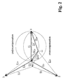
- FIG. 2 is a graphical vector representation of the symmetrical line-to-neutral voltages of a network, the unsymmetrical line-to-neutral voltages in an unfaulted state of the network, the unsymmetrical line-to-neutral voltages during a fault and the corresponding zero-sequence voltages during the unfaulted and faulted condition of the network for a single-phase ground fault in a compensated network;
- Figure 3 illustrates an exemplary embodiment of a compensated medium-voltage network comprising both radial feeders and ring feeders.
- the feeders connected in a ring are supplied from one and the same substation, e.g. a 110/20 kV station.
- sum current and zero-sequence current are used equally when reference is made to the sum of the phase currents, particularly to the vector sum of the phase currents or to a sum current computed from the respective phasors.
- the sum current of a feeder can be measured using a cable current transformer, for example.
- the line-to-ground admittance Y 0i of a feeder i can be computed by dividing the change in the zero-sequence current ⁇ I 0i with the change in the zero-sequence voltage ⁇ U 0 of the feeder.
- the real part of represents the conductance between the phases of the feeder and the ground
- the imaginary part represents the susceptance of the phases to the ground due to the line-to-ground capacitances:
- the physical leakage resistance of an unfaulted feeder connected to a feeder is in the range of megaohms, and thus, the line-to-ground conductance is in the order of 10 -6 1/ ⁇ .
- the line-to-ground conductance values computed from Eq. 1 on the basis of field measurements are often within the same decade with the corresponding line-to-ground susceptance of the feeder.
- the line-to-ground susceptance values thus obtained may be considered to represent a virtual parameter value, chiefly traceable to measurement inaccuracies.
- the resolution of measurement devices at substations and the sampling rate of digital protective relays are generally not adequate for determining the physically correct line-to-ground conductance of a feeder or the entire network by this technique.
- a more sensitive detection method in monitoring the electrical insulation condition of a feeder in an electric network is obtained if the line leakage resistance in the normal condition of the feeder is ignored altogether, and instead, only the line-to-ground susceptance of the feeder and the reactive component of the sum current thereof are used for computing the fault resistance.
- This approach allows the detection of a ground fault to be extended to fault resistances of significantly higher magnitude than what has been possible by previously known methods and, moreover, its computation algorithms give fault resistance values of an improved accuracy.
- the line-to-ground susceptance computed from Eq. 1 corresponds to the electrical length of the feeder to a very good accuracy.
- the fault resistance is computed individually for each feeder.
- the computation uses only the imaginary part of the unfaulted-condition line-to-ground admittance of the feeder, that is, the line-to-ground susceptance, it is necessary to eliminate the reactive component from the sum current of the feeder.
- the sum current of the feeder also contains a component caused by the unsymmetry of the line-to-ground capacitances.
- the unsymmetry of the line-to-ground capacitances gives rise to a small zero-sequence voltage in the network even under normal conditions. Hence, the effect of the unsymmetry of the line-to-ground capacitances must be eliminated from both the zero-sequence voltage and the sum currents of the feeders. In this manner, the computation is brought back to that of a symmetrical initial condition.
- the computation starts with a change in the zero-sequence voltage of the network.
- the absolute value of the zero-sequence voltage change is computed from Eq. 2 given below. If the zero-sequence voltage change is caused by a ground fault, ⁇ U 0 is equal to the zero-sequence voltage component caused the ground fault (see FIG. 1) inasmuch the zero-sequence voltage of the unfaulted condition is subtracted from the zero-sequence voltage measured during the ground fault. This step eliminates the contribution of capacitance unsymmetry to the measured value of the zero-sequence voltage.
- ⁇ U 0 U 0 M - U 0 ' ⁇ U 0 k
- the fault resistance is computed individually for each feeder from the equation given below. All underlined symbols refer to vector variables. The vectors used in the computation are determined by simultaneous measurements. The computation of fault resistance is performed separately for each phase using the line-to-ground voltage of the faulted phase in the equations.
- the zero-sequence susceptance values B 0 of a feeders are always updated in connection with low-resistance ground faults. If necessary, also B 0 values computed from network data may be used.
- the method disclosed herein is not sensitive to an error in the value of the zero-sequence susceptance of a feeder, because it does not need the value of B 0 at all for identifying a faulted phase and, besides, also the order of magnitude of the fault resistance indicates the occurrence of a fault.
- the method described above may be carried out repetitively at arbitrary instants of time in order to compute R F so that a desired feeder or feeders can be monitored on a continuous basis.
- R Fk its predetermined threshold value
- the time interval in the determination of R F may be made as short as one cycle of the network frequency thus allowing even temporary ground faults of short duration to be identified.
- a high-voltage electrical distribution network is usually configured using ring feeders to provide alternative feed paths in a faulted network and to improve the overall reliability of the network.
- the feeders comprise two radial feeders supplied by the feeders (feeders A and B of FIG. 3) that are connected to each other in the field so as to form a ring feeder.
- Very high-resistance ground faults occurring in a ring feeder can be identified using the same algorithm (Eq. 3) as that applicable in the case of a radial feeder. The only difference is that sum current of the radial feeder is replaced by the sum current of the zero-sequence current of the radial feeder.
- the fault resistance is computed from Eq. 5 with the feeders A and B being connected in a ring using the notations of FIG. 3.
- the term "total sum current of ring-connected feeders" is used to denote the sum of the zero-sequence currents of feeders A and B.
- Fault resistance computation is performed separately for each phase using the line-to-neutral voltage of the faulted phase in the equations.
- the ring connection of the feeders does not interfere with the identification of the faulted phase inasmuch this step is carried out by means of the line-to-neutral voltages and the zero-sequence voltage in the manner explained below.
- the first task is to identify the faulted phase.
- the identification of a faulted phase is performed in a slightly different manner in regard to an isolated-neutral network and a resonant-ground network.
- the indication technique of a faulted phase in itself serves as a sensitive method of ground fault indication.
- FIG. 1 are shown in vector form the symmetrical line-to-neutral voltages of an isolated-neutral network, the unsymmetrical line-to-neutral voltages in an unfaulted state, the unsymmetrical line-to-neutral voltages during a ground fault, the zero-sequence voltage in an unfaulted state, the zero-sequence voltage measured during a ground fault, and the zero-sequence voltage representing a system of symmetrical initial state after a ground fault.
- the zero-sequence voltage and the voltage of a faulted phase trace a semicircular arc as a function of the fault resistance.
- the faulted phase is interpreted to be the one having its line-to-neutral voltage leading the reference vector ⁇ U 0 by approximately 90°.
- the lead angle may deviate a few degrees from this threshold value.
- FIG. 1 The following notations are used in FIG. 1:
- the voltage between a faulted phase and ground during a ground fault is independent from the capacitance unsymmetry of the network and the zero-sequence voltage measured in an unfaulted state ( Figure 1).
- a zero-sequence voltage corresponding to a symmetrical initial state is used, because only under this condition Eq. (9) defining the phase angles is valid.
- the phasor of the zero-sequence voltage in an unfaulted state and the phasor of the zero-sequence voltage during a fault are known from measurements.
- the nominator of Eq. 3 is positive in the case of a faulted phase and negative in the case of unfaulted phases. This rule may be used to check the indication result of a faulted phase.
- the value of ⁇ U 0 corresponding to an unfaulted initial state may also be determined in another fashion.
- those line-to-line voltages of the network which do not change as a consequence of a ground fault are measured continuously. These line-to-line voltages can be used to determine the symmetrical line-to-neutral voltages U 1 , U 2 and U 3 . These line-to-line voltages should be approximately equal for both an unfaulted state and a ground fault.
- the absolute values of the line-to-line voltages differ from each other slightly due to measurement inaccuracy. The voltage may also contain a slight negative-sequence component.
- each one of the symmetrical line-to-neutral voltages U 1 , U 2 , U 3 (FIG. 1) are set equal to the value of
- the phase angle of U 1 equal to that of vector ( U 1 ' - U 0 ') or, respectively, during a ground fault, equal to that of vector ( U 1F - ( U 0M - U 0 ')).
- arg( U 1 ) 30°
- arg( U 2 ) -90°
- arg( U 3 ) 150°.
- the absolute values and phase angles of the line-to-neutral voltages are determined in this manner, ideally symmetrical voltages can be utilized in the computations.
- the zero-sequence voltage ⁇ U 0 corresponding to a symmetrical initial state can be determined directly by means of the measured voltage of the faulted phase and the symmetrical line-to-neutral voltage computed in the above-described manner (FIG. 1 and Eq. 12).
- the above-described method already inherently offers a sensitive technique of fault indication.
- the zero-sequence voltage vector U 0 ' which may be present even in an unfaulted state due the capacitance unsymmetry of the network, can have any phase angle. If the network zero-sequence voltage changes due to a change in line length or unsymmetry, it may haphazardly occur that any one of the line-to-neutral voltage leads by 90° the vector ⁇ U 0 representing a change in the zero-sequence voltage. While the probability of such a situation is small, the result from the identification of a faulted phase is not inherently a fully adequate condition for interpreting the existence of a fault.
- the magnitude of the fault resistance will give proof that none of the feeders is faulted. Accordingly, the identification of a possibly faulted phase is a prerequisite for the computation of the fault resistance.
- FIG. 2 illustrates the symmetrical line-to-neutral voltages of a resonant-ground network, the unsymmetrical line-to-neutral voltages in an unfaulted state, the unsymmetrical line-to-neutral voltages during a ground fault, the zero-sequence voltage in an unfaulted state, the zero-sequence voltage representing a system of symmetrical initial state after a ground fault, and the neutral voltage measured during a ground fault.
- the voltages are denoted by the same symbols as those used in FIG. 1.
- the zero-sequence voltage and the voltage of a faulted phase trace an arc as a function of the fault resistance, the radius of the arc being determined by the degree of compensation in the network.
- the upper semicircular arc corresponds to an isolated-neutral situation and the lower semicircular arc to infinite overcompensation.
- the phase angle ⁇ U ⁇ F of the voltage of a faulted phase may vary between 90° and 180° in an undercompensated network and between -90° and -180° in an overcompensated network.
- the phase angle ⁇ U ⁇ F approaches 90°, while in a clearly overcompensated network the angle is -90°.
- the angle ⁇ U ⁇ F approaches 180°.
- the identification of a faulted phase by this technique is not a method as effective in fault indication as that described above for the identification of a faulted phase of an isolated-neutral network.
- This is because changes in the zero-sequence voltage caused by reasons other than a ground fault are more likely to shift the phase angle of any one of line-to-neutral voltage relative to the zero-sequence voltage ⁇ U 0 to within a range of angle values where the phase is interpreted as faulted.
- the computed fault resistance herein reveals that the feeder is unfaulted.
- the method indicates the phase which may be faulted. From the angle ⁇ U ⁇ F , it is also possible to infer whether the network is under- or overcompensated.
- the angle ⁇ U ⁇ F will also make it possible to determine the degree of compensation of the network. This is particularly advantageous when the network is equipped with fixed (nonadjustable) compensation, either at a substation or in a distributed manner at different points of the network, and there is no measurement data available on the neutral currents passing through the reactors. In such a situation, it is difficult to accurately determine the degree of compensation in the network by any other means.
- the zero-sequence voltage vector ( ⁇ U 0 ) is directed in the opposite direction relative to the vector of the symmetrical line-to-neutral voltage of the faulted phase.
- the voltage of the faulted phase is always the lowest, because the residual current is then fully resistive. Also this information can be used as an ensuring condition in the determination of a faulted phase in a network that can be tuned to resonance.
- both the method according to Eq. 3 as well as prior-art methods suited for identifying high-resistance faults correctly to the faulted feeder need realtime information on the electrical length of the feeder.
- a technique is needed capable of eliminating the uncertainty factors associated with the ground susceptance of the feeder.
- the configuration of the feeder does not necessarily correspond to the value of ground susceptance B 0 stored in the system memory if a change has occurred in the feeder configuration just before the fault.
- the stored value of B 0 may also contain error due to inaccuracy in measurements.
- the method described below functions always correctly even if the fault occurs on a feeder whose configuration has changed just recently.
- the method does not need the ground susceptance (B 0 ), whereby inaccuracies in the value thereof cannot affect the result of the indication algorithm.
- the reactive component of the sum current vector is directed opposite to the direction of the same vector in an unfaulted feeder.
- the reactive and real components of the sum current are discussed separately.
- the sum current vector component related to the capacitance unsymmetry may have any direction, which means that it can contribute virtual real or reactive current to the total sum current. Hence, its effect must be eliminated.
- the fault indication method based on the indication of a change in the reactive component of the zero-sequence sum current is suited for use in isolated-neutral and compensated networks.
- the compensation offset undercompensation
- electrical length B 0
- the method is not suited for use on said underground feeder inasmuch the vector direction of the reactive component of the zero-sequence sum current does not change at the occurrence of a ground fault.
- the method is suited for use on other feeders supplied from the same substation, because the ground-fault current they can produce under such conditions remains smaller than 30 % of the maximum overall ground-fault current of the network.
- the compensation offset undercompensation
- B 0 electrical length of any individual feeder
- the method based on monitoring the direction of change in the reactive component of the sum current (Eqs. 14 and 15) is also suited for use in network compensated with distributed arc-suppression elements provided that the compensation units located at the feeders are dimensioned so as to avoid overcompensation of the feeders during a ground fault, which is a design rule generally adopted. If the ground-fault protection is based on the monitoring of the real component of the sum current, whereby the feeders may become overcompensated without disturbing the protective system, also the fault indication scheme can be implemented based on the monitoring of the real component of the sum current.
- fault indication can be implemented based on monitoring the direction of change in the real component of the sum current (Eqs. 16 and 17).
- the real component of the sum current vector invoked by the leakage resistance of the unfaulted feeder is in phase with the zero-sequence voltage, which means that Eq. 16 is valid.
- the leakage resistance of the feeder is very high (in the order of megaohms). Therefore, the real component of the sum current vector during a ground fault is insignificantly small, whereby high demands are imposed on the measurement accuracy.
- the predetermined threshold value may be used as a criterion complementing the results obtained from Eqs. 16 and 17.
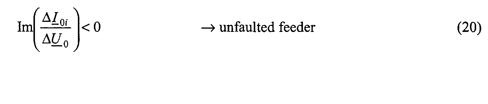
- An alternative technique of indicating an impending fault condition of medium-voltage feeder is to compute the ground admittance of the feeder from changes in the sum current and zero-sequence voltage and then to examine the sign of the imaginary part of the ground admittance, that is, of the ground susceptance.
- the ground conductance of the feeder is ignored in the examination inasmuch this parameter cannot be determined at a sufficiently good accuracy by concurrent measurement methods. Even the sign of a ground conductance value acquired by measurements may be incorrect as compared with that obtained from a theoretical treatise.
- the criteria for identifying a feeder as either unfaulted or faulted are: The computation is started when the change in the zero-sequence voltage exceeds a predetermined threshold value (Eq. 13).
- Eq. 13 a predetermined threshold value
- a high-voltage electrical distribution network is conventionally constructed using ring feeders in order to provide alternative feed paths in a faulted network and to improve the overall reliability of the network.
- ring feeders in order to provide alternative feed paths in a faulted network and to improve the overall reliability of the network.
- FIG. 3 the indication of a ground fault occurring in a ring feeder supplied from two feeders of one and the same substation.
- Ground faults of very high resistance affecting a feeder supplied from feeders connected into a ring configuration can be indicated using the same algorithms (Eqs. 14 - 21) as those applicable to a radial feeder.
- the only difference herein is that the sum current of a radial feeder is replaced by the sum current of the feeders feeding the ring.
- the sum of the zero-sequence currents of feeders A and B shown in FIG. 3 are referred to as "the total sum current of the ring feeder.”
- the methods disclosed herein provide a minimum detection sensitivity of 190 kohm.
- the indication method of Eqs. 3 and 5 based on the computation of the fault resistance is usable in both neutral-isolated and compensated networks.
- Eqs. 14 and 15, as well as 20 and 21, can be applied within the limiting condition explained in item II (Indication of an impending fault condition of feeder or faulted feeder in an electrical network from the direction of change in the sum current vector). All of the methods disclosed herein are usable for both radial feeders and ring feeders. Each one of the monitored feeders must be equipped with multifunction protective relays (at feeder terminals).
- the measurement data typically needed comprise one line-to-line voltage, the zero-sequence voltage, the line-to-neutral voltages (for computation of fault resistance), and the sum currents of the feeders.
- Eqs. 14 - 21 do not need measurement data about the line-to-neutral voltages. All the measurement facilities required in the method are readily available at any substation.
- an underlined symbol (e.g., ⁇ U 0 ) denotes a vector.
- the vectors (expressed by phase angles and absolute values) used in the computations are determined by simultaneous measurements to within the accuracy affordable by the practice of measurement techniques.
Landscapes
- Emergency Protection Circuit Devices (AREA)
- Locating Faults (AREA)
- Testing Of Short-Circuits, Discontinuities, Leakage, Or Incorrect Line Connections (AREA)
Abstract

Description
- R0i =
- = leakage resistance from the three phases to the ground
- G0i =
- line-to-ground conductance summed for the three phases
- C0i =
- line-to-ground capacitance summed for the three phases
- B0i =
- line-to-ground susceptance summed for the three phases
- ω =
- angular frequency.
- U0' =
- measured zero-sequence voltage prior to change (normal network condition)
- U0M =
- measured zero-sequence voltage after change (possibly faulted network condition)
- RFi =
- fault resistance at feeder i
- UνF =
- voltage between faulted phase and ground
- ϕU
νF = - differential phase angle between voltage vector U νF of faulted phase and vector ΔU 0
- ΔI0i =
- change in the sum current at feeder i
- I01i =
- sum current at feeder i prior to change in zero-sequence voltage
- I02i =
- sum current at feeder i after change in zero-sequence voltage
- ϕI
0i = - differential phase angle between vectors ΔI 0i and ΔU 0
- B0i =
- summed line-to-ground susceptance of the three phases at feeder i (imaginary part of line-to-ground admittance).
- RFi =
- fault resistance at ring-connected feeder i
- U0' =
- zero-sequence voltage of network prior to change
- U0M =
- zero-sequence voltage of network after change
- I0A1 =
- zero-sequence sum current of ring-connected feeder A prior to change in zero-sequence voltage
- I0B1 =
- zero-sequence sum current of ring-connected feeder B prior to change in zero-sequence voltage
- I0A2 =
- zero-sequence sum current of ring-connected feeder A after change in zero-sequence voltage
- I0B2 =
- zero-sequence sum current of ring-connected feeder B after change in zero-sequence voltage
- ϕU
0 = - phase angle of vector ΔU 0
- ϕI
0AB - differential phase angle between vectors ΔI 0AB and ΔU 0
- B0r =
- summed line-to-ground susceptance of a ring-connected feeder (FIG. 3: A+B) (sum of all three phases).
- 1,2,3 =
- phase subindexes
- U0' =
- zero-sequence voltage during unfaulted state
- U0M =
- zero-sequence voltage measured during ground fault
- ΔU0 =
- zero-sequence voltage during ground fault corresponding to a symmetrical initial state
- U1,U2,U3 =
- symmetrical line-to-neutral voltages
- U1',U2',U3' =
- unsymmetrical line-to-ground voltages during unfaulted state
- U1F, U2F, U3F =
- unsymmetrical line-to-ground voltages during ground fault
- U0' =
- measured zero-sequence voltage prior to the change (normal state of network)
- U0M =
- measured zero-sequence voltage after the change (faulted state of network)
- ΔI01i =
- change in reactive component of sum current at feeder i
- ΔI0pi =
- change in real component of sum current at feeder i
- I01i =
- sum current of feeder i prior to the change
- I02i =
- sum current of feeder i after the change
- U01 =
- zero-sequence voltage prior to the change
- U02 =
- zero-sequence voltage after the change
- ϕI
0i = - phase angle of sum current change vector ΔI 0i
- ϕU0=
- phase angle of zero-sequence voltage change vector ΔU 0.

- U0' =
- zero-sequence voltage of network prior to the change
- U0M =
- zero-sequence voltage of network after the change
- I0A1 =
- sum current of feeder A prior to the change in zero-sequence voltage
- I0B1 =
- sum current of feeder B prior to the change in zero-sequence voltage
- I0A2 =
- sum current of feeder A after the change in zero-sequence voltage
- I0B2 =
- sum current of feeder B after the change in zero-sequence voltage
- ϕI
0AB = - phase angle of change vector ΔI 0AB
- ϕU
0 = - phase angle of change vector ΔU 0
- B0r =
- summed ground susceptance (sum of all three phases) of the ring feeder feeders (FIG. 3: A+B)
Claims (11)
- A method for identification of an impending fault condition or faulted feeder or a ring feeder in an electrical distribution system, the method comprising the steps ofcharacterized in that the impending fault condition of feeder or faulty feeder or feeder branch is identified based oncomputing the absolute value |Δ U 0| = | U 02 - U 01| of the zero-sequence voltage change in vector format under a changing condition of the network, whereby U 01 is the zero-sequence voltage measured prior to the change and U 02 is the zero-sequence voltage measured after the change,testing the computed value |Δ U 0| against a predetermined threshold value for the condition |Δ U 0| ≥ U 0 k , andstarting the identification of the impending fault condition of feeder or faulty feeder or feeder branch if the change in the zero-sequence voltage exceeds the predetermined threshold value,the direction of change in the reactive or the real component of the sum current vector, or, alternatively,the sign of the imaginary partof the ground admittance, whereby a positive sign indicates a faulty feeder.

- The method of claim 1, characterized in that a fault in an impending fault condition of feeder or faulty feeder is identified from the direction of change in the reactive component of the sum current vector according to the following equations:
- ΔI01i =
- change in reactive component of sum current at feeder i
- I01i =
- sum current of feeder i prior to the change
- I02i =
- sum current of feeder i after the change
- U01 =
- zero-sequence voltage prior to the change
- U02 =
- zero-sequence voltage after the change
- ϕI
0i = - phase angle of sum current change vector ΔI 0i
- ϕU
0 = - phase angle of zero-sequence voltage change vector ΔU 0.
- The method of claim 1, characterized in that an impending fault condition of feeder or faulty feeder is identified from the direction of change in the real component of the sum current vector according to the following equations:
- ΔI0pi =
- change in real component of sum current at feeder i
- I01i =
- sum current of feeder i prior to the change
- I02i =
- sum current of feeder i after the change
- U01 =
- zero-sequence voltage prior to the change
- U02 =
- zero-sequence voltage after the change
- ϕI
0i = - phase angle of sum current change vector ΔI 0i
- ϕU
0 = - phase angle of zero-sequence voltage change vector ΔU 0.
- The method of claim 1, characterized in that a faulty feeder is identified by examining the sign of the imaginary part of the ground admittance (Y 0i) as follows:
 where
where
- ΔI0i =
- change in the sum current of feeder i
- ΔU0 =
- change in zero-sequence voltage.
- The method of claim 1 for identification of a fault in a ring-connected feeder of an electrical network, characterized in that a fault in an impending fault condition of feeder or faulty ring feeder (AB) is identified by examining the direction of change in the reactive component of the total sum current (I 0A + I 0B) as follows:
- ΔI0AB1 =
- change in the reactive component of the total sum current (I 0A + I 0B) of the ring-connected feeder
- ΔI0AB =
- change in the total sum current (I 0A + I 0B) of the ring-connected feeder
- U01 =
- network zero-sequence voltage prior to the change
- U02 =
- network zero-sequence voltage after the change
- I0A1 =
- sum current of ring-connected feeder A prior to the change in the zero-sequence voltage
- I0B1 =
- sum current of ring-connected feeder B prior to the change in the zero-sequence voltage
- I0A2 =
- sum current of ring-connected feeder A after the change in the zero-sequence voltage
- I0B2 =
- sum current of ring-connected feeder B after the change in the zero-sequence voltage
- ϕI
0AB = - phase angle of vector ΔI 0AB
- ϕU
0 = - phase angle of vector ΔU0 .
- The method of claim 1 for identification of a fault in a ring-connected feeder of an electrical network, characterized in that a fault in an impending fault condition of feeder or faulty ring feeder (AB) is identified by examining the direction of change in the real component of the total sum current (I 0A + I 0B) as follows:
- ΔI0ABp =
- change in the reactive component of the total sum current (I 0A + I 0B) of the ring-connected feeder
- ΔI0AB =
- change in the total sum current (I 0A + I 0B) of the ring-connected feeder
- U01 =
- network zero-sequence voltage prior to the change
- U02 =
- network zero-sequence voltage after the change
- I0A1 =
- sum current of ring-connected feeder A prior to the change in the zero-sequence voltage
- I0B1 =
- sum current of ring-connected feeder B prior to the change in the zero-sequence voltage
- I0A2 =
- sum current of ring-connected feeder A after the change in the zero-sequence voltage
- I0B2 =
- sum current of ring-connected feeder B after the change in the zero-sequence voltage
- ϕI
0AB = - phase angle of vector ΔI 0AB
- ϕU
0 = - phase angle of vector ΔU 0.
- The method of claim 1 for identification of a fault in a ring-connected feeder of an electrical network, characterized in that a fault in an impending fault condition of feeder or faulty ring feeder (AB) is identified by examining the sign of the imaginary part of ground admittance computed from the total sum current (I 0A + I 0B) as follows:


- ΔI0AB =
- change in the total sum current (I 0A + I 0B) of the ring-connected feeder
- U01 =
- network zero-sequence voltage prior to the change
- U02 =
- network zero-sequence voltage after the change
- I0A1 =
- sum current of ring-connected feeder A prior to the change in the zero-sequence voltage
- I0B1 =
- sum current of ring-connected feeder B prior to the change in the zero-sequence voltage
- I0A2 =
- sum current of ring-connected feeder A after the change in the zero-sequence voltage
- I0B2 =
- sum current of ring-connected feeder B after the change in the zero-sequence voltage
- The method of any one of foregoing claims, characterized in that additionallywherethe faulted phase is identified with the help of the measured line-to-phase voltages and the zero-sequence voltage ΔU 0 = U 0M - U 0' (Eq. 6 or 10),for each one of the feeders i is computed the value of the fault resistance RFi using the equation:
- UνF =
- line-to-ground voltage of faulted phase
- ϕU
vF = - differential phase angle between line-to-ground voltage vector ΔU νF and differential voltage vector ΔU 0
- ΔI0i =
- change of sum current at feeder i due a change in zero-sequence voltage
- ϕI
0i = - differential phase angle between vectors ΔI0i and ΔU 0
- B0i =
- summed line-to-ground susceptance of three phases of feeder i (imaginary part of ground admittance)
the faulted phase is interpreted to be the one with a fault resistance (RFi) lower than a predetermined threshold value (RFk) (that is, RFi < RFk), and,in the case of a low-resistance ground fault (e.g., having a fault resistance smaller 1 kohm), the computed values of RFi are compared with each other and faulted phase is interpreted to be the one with the lowest fault resistance. - The method of any one of foregoing claims for determining the insulation condition of a ring-connected feeder, characterized in that additionallywherethe faulted phase is identified with the help of the measured line-to-phase voltages and the zero-sequence voltage ΔU 0 = U 0M - U 0' (Eq. 6 or 10),for each one of the ring-connected feeders is computed the value of the fault resistance RFi using the equation:
- RFi =
- fault resistance of ring-connected feeder i
- U0' =
- network zero-sequence voltage prior to the change
- U0M =
- network zero-sequence voltage after the change
- I0A1 =
- sum current of ring-connected feeder A prior to the change in the zero-sequence voltage
- I0B1 =
- sum current of ring-connected feeder B prior to the change in the zero-sequence voltage
- I0A2 =
- sum current of ring-connected feeder A after the change in the zero-sequence voltage
- I0B2 =
- sum current of ring-connected feeder B after the change in the zero-sequence voltage
- ϕU
0 = - phase angle of vector ΔU 0
- ϕI
0AB = - differential phase angle between vector ΔI 0AB and vector ΔU 0
- B0r =
- summed line-to-ground susceptance of a ring-connected feeder (FIG. 3: A+B) (sum of all three phases).
- The method of any one of foregoing claims for use in an isolated-neutral characterized in that additionallythe line-to-ground voltages are determined in vector format, andthe faulted phase is interpreted to be the one having the phase angle of its line-to-ground voltage leading the zero-sequence voltage change vector ΔU 0 = U 02 - U 01 by approximately 90°.
- The method of any one of foregoing claims1-9 for use in a compensated network, characterized in that additionallythe line-to-ground voltages are determined in vector format, andthe faulted phase is interpreted to be the one having the phase angle of its line-to-ground voltage falling within a predetermined range relative to the zero-sequence voltage change vector ΔU 0.
Applications Claiming Priority (2)
| Application Number | Priority Date | Filing Date | Title |
|---|---|---|---|
| FI20002096A FI108893B (en) | 2000-09-22 | 2000-09-22 | A method for detecting a faulty or faulty output or branch of a power grid |
| FI20002096 | 2000-09-22 |
Publications (3)
| Publication Number | Publication Date |
|---|---|
| EP1195874A2 true EP1195874A2 (en) | 2002-04-10 |
| EP1195874A3 EP1195874A3 (en) | 2005-12-14 |
| EP1195874B1 EP1195874B1 (en) | 2012-04-25 |
Family
ID=8559143
Family Applications (1)
| Application Number | Title | Priority Date | Filing Date |
|---|---|---|---|
| EP20010660176 Expired - Lifetime EP1195874B1 (en) | 2000-09-22 | 2001-09-21 | Method for identification of a faulting or faulted sending end or feeder branch in an electrical distribution system |
Country Status (2)
| Country | Link |
|---|---|
| EP (1) | EP1195874B1 (en) |
| FI (1) | FI108893B (en) |
Cited By (30)
| Publication number | Priority date | Publication date | Assignee | Title |
|---|---|---|---|---|
| WO2007147941A1 (en) * | 2006-06-20 | 2007-12-27 | Abb Technology Ag | System and method for determining phase-to-earth admittances of a three-phase electric line |
| WO2010115474A1 (en) * | 2009-04-10 | 2010-10-14 | Areva T&D Uk Ltd | Method and system for transient and intermittent earth fault detection and direction determination in a three-phase median voltage electric power distribution system |
| WO2012110698A1 (en) * | 2011-02-15 | 2012-08-23 | Abb Technology Ag | Method and apparatus for detecting earth fault |
| CN103163413A (en) * | 2013-03-06 | 2013-06-19 | 福建省电力有限公司 | Single-phase ground fault type diagnosis method for ultra-high voltage alternating current transmission line |
| CN103197201A (en) * | 2013-03-07 | 2013-07-10 | 福建省电力有限公司 | Low-resistance, medium-resistance and high-resistance grounding fault type recognition method of power transmission line |
| CN103245888A (en) * | 2013-05-10 | 2013-08-14 | 国家电网公司 | Circuit interphase fault single-terminal location method capable of preventing additional fault location influence |
| CN103248026A (en) * | 2013-05-10 | 2013-08-14 | 国家电网公司 | Line single-phase ground fault relay protection method capable of preventing distributed capacitive current and transitional resistance |
| CN103762567A (en) * | 2014-02-18 | 2014-04-30 | 国家电网公司 | Electric transmission line single-phase earth fault relay protection method based on fault position factor |
| EP3062410A1 (en) * | 2015-02-27 | 2016-08-31 | General Electric Technology GmbH | A protection apparatus |
| CN106786470A (en) * | 2015-11-19 | 2017-05-31 | 中国石油化工股份有限公司 | A kind of power network neutral point flexible ground system |
| CN108335227A (en) * | 2017-12-22 | 2018-07-27 | 国网河北省电力有限公司故城县供电分公司 | Branch switch sudden load change alarm method and terminal device |
| EP3361273A1 (en) * | 2017-02-09 | 2018-08-15 | Sprecher Automation GmbH | Method for controlling a distance protection relay by detecting conductor earth faults |
| CN109557399A (en) * | 2018-12-14 | 2019-04-02 | 海南电网有限责任公司琼海供电局 | A kind of distribution network fault monitoring method and device |
| CN110780160A (en) * | 2019-12-06 | 2020-02-11 | 广东电网有限责任公司 | Arc light high-resistance grounding fault detection method and device |
| CN111707901A (en) * | 2020-04-21 | 2020-09-25 | 国网安徽省电力有限公司 | Single-phase-to-ground phase discrimination method for distribution network based on voltage amplitude characteristics |
| CN112039031A (en) * | 2019-06-03 | 2020-12-04 | 李景禄 | Differentiation processing and fault area isolation method for single-phase earth fault of power distribution network |
| CN112067884A (en) * | 2020-09-16 | 2020-12-11 | 广东电网有限责任公司 | Feeder branch fault detection method and system |
| CN112152191A (en) * | 2020-09-01 | 2020-12-29 | 国网陕西省电力公司榆林供电公司 | Fault processing method, device and storage medium for distribution line |
| CN112180290A (en) * | 2020-09-29 | 2021-01-05 | 西安热工研究院有限公司 | A generator stator ground fault location method |
| CN112305375A (en) * | 2020-10-26 | 2021-02-02 | 西安工程大学 | A high-resistance grounding fault line selection method for resonant grounding system |
| CN112383073A (en) * | 2020-11-26 | 2021-02-19 | 国网北京市电力公司 | Analysis method and analysis device for zero sequence current value in power distribution network and power grid monitoring terminal |
| CN112540322A (en) * | 2020-12-29 | 2021-03-23 | 广东电网有限责任公司电力科学研究院 | Line selection method, device and equipment for single-phase earth fault line of feeder line of transformer substation |
| CN112731054A (en) * | 2020-12-19 | 2021-04-30 | 国网河南省电力公司电力科学研究院 | Power distribution network single-phase earth fault line selection method based on zero sequence residual voltage suppression |
| CN112909904A (en) * | 2021-03-03 | 2021-06-04 | 广东电网有限责任公司 | Resistance grounding system and control method thereof |
| CN113687188A (en) * | 2021-09-14 | 2021-11-23 | 广东电网有限责任公司 | Fault line selection method and device based on two-stage zero-sequence power change |
| RU2771222C1 (en) * | 2021-01-13 | 2022-04-28 | Акционерное общество "Сетевая компания" | Method for determining a damaged feeder in case of single phase to ground fault in a distribution electrical network |
| CN115542071A (en) * | 2022-08-23 | 2022-12-30 | 国网吉林省电力有限公司白城供电公司 | Signal-free area data transmission method |
| CN116540013A (en) * | 2023-04-10 | 2023-08-04 | 国网安徽省电力有限公司芜湖供电公司 | Distribution network single-phase disconnection fault positioning method based on voltage information |
| CN119395453A (en) * | 2024-10-28 | 2025-02-07 | 广东电网有限责任公司 | A method, device and terminal equipment storage medium for fault detection of power distribution system |
| CN119881530A (en) * | 2024-12-31 | 2025-04-25 | 安徽理工大学 | Flexible grounding active power distribution network single-phase earth fault line selection method and system |
Families Citing this family (3)
| Publication number | Priority date | Publication date | Assignee | Title |
|---|---|---|---|---|
| CN113064025B (en) * | 2021-03-26 | 2022-06-21 | 国家电网有限公司 | Ground fault line selection tripping method and system in resonance grounding system |
| CN116559595B (en) * | 2023-06-05 | 2026-06-12 | 青岛鼎信通讯股份有限公司 | A grounding fault detection method based on a data acquisition device |
| CN117810901A (en) * | 2024-01-02 | 2024-04-02 | 保定浪拜迪电气股份有限公司 | Line neutral point non-effective ground fault line selection method and device |
Family Cites Families (1)
| Publication number | Priority date | Publication date | Assignee | Title |
|---|---|---|---|---|
| FI100922B (en) * | 1996-11-04 | 1998-03-13 | Abb Transmit Oy | Method for detecting and locating a grounding fault with great resistance in an electricity distribution network |
-
2000
- 2000-09-22 FI FI20002096A patent/FI108893B/en not_active IP Right Cessation
-
2001
- 2001-09-21 EP EP20010660176 patent/EP1195874B1/en not_active Expired - Lifetime
Cited By (44)
| Publication number | Priority date | Publication date | Assignee | Title |
|---|---|---|---|---|
| WO2007147941A1 (en) * | 2006-06-20 | 2007-12-27 | Abb Technology Ag | System and method for determining phase-to-earth admittances of a three-phase electric line |
| WO2010115474A1 (en) * | 2009-04-10 | 2010-10-14 | Areva T&D Uk Ltd | Method and system for transient and intermittent earth fault detection and direction determination in a three-phase median voltage electric power distribution system |
| WO2012110698A1 (en) * | 2011-02-15 | 2012-08-23 | Abb Technology Ag | Method and apparatus for detecting earth fault |
| CN103163413B (en) * | 2013-03-06 | 2015-07-01 | 福建省电力有限公司 | Single-phase ground fault type diagnosis method for ultra-high voltage alternating current transmission line |
| CN103163413A (en) * | 2013-03-06 | 2013-06-19 | 福建省电力有限公司 | Single-phase ground fault type diagnosis method for ultra-high voltage alternating current transmission line |
| CN103197201A (en) * | 2013-03-07 | 2013-07-10 | 福建省电力有限公司 | Low-resistance, medium-resistance and high-resistance grounding fault type recognition method of power transmission line |
| CN103197201B (en) * | 2013-03-07 | 2015-06-03 | 福建省电力有限公司 | Low-resistance, medium-resistance and high-resistance grounding fault type recognition method of power transmission line |
| CN103245888A (en) * | 2013-05-10 | 2013-08-14 | 国家电网公司 | Circuit interphase fault single-terminal location method capable of preventing additional fault location influence |
| CN103248026A (en) * | 2013-05-10 | 2013-08-14 | 国家电网公司 | Line single-phase ground fault relay protection method capable of preventing distributed capacitive current and transitional resistance |
| CN103245888B (en) * | 2013-05-10 | 2015-10-28 | 国家电网公司 | The circuit inter-phase fault single-end ranging of anti-additional fault distance impact |
| CN103248026B (en) * | 2013-05-10 | 2015-11-04 | 国家电网公司 | The single-phase line earth fault relay protection method of anti-capacitance current and transition resistance |
| CN103762567A (en) * | 2014-02-18 | 2014-04-30 | 国家电网公司 | Electric transmission line single-phase earth fault relay protection method based on fault position factor |
| CN103762567B (en) * | 2014-02-18 | 2016-02-03 | 国家电网公司 | Based on the transmission line one-phase earth fault relay protecting method of the abort situation factor |
| US10700508B2 (en) | 2015-02-27 | 2020-06-30 | General Electric Technology Gmbh | Protection apparatus |
| CN106033881B (en) * | 2015-02-27 | 2019-06-04 | 通用电气技术有限公司 | protective device |
| CN106033881A (en) * | 2015-02-27 | 2016-10-19 | 阿尔斯通技术有限公司 | A protection apparatus |
| WO2016135266A1 (en) * | 2015-02-27 | 2016-09-01 | General Electric Technology Gmbh | A protection apparatus |
| EP3062410A1 (en) * | 2015-02-27 | 2016-08-31 | General Electric Technology GmbH | A protection apparatus |
| CN106786470A (en) * | 2015-11-19 | 2017-05-31 | 中国石油化工股份有限公司 | A kind of power network neutral point flexible ground system |
| CN106786470B (en) * | 2015-11-19 | 2021-03-02 | 中国石油化工股份有限公司 | Flexible grounding system for neutral point of power grid |
| EP3361273A1 (en) * | 2017-02-09 | 2018-08-15 | Sprecher Automation GmbH | Method for controlling a distance protection relay by detecting conductor earth faults |
| CN108335227B (en) * | 2017-12-22 | 2020-12-29 | 国网河北省电力有限公司故城县供电分公司 | Branch switch load sudden change alarm method and terminal equipment |
| CN108335227A (en) * | 2017-12-22 | 2018-07-27 | 国网河北省电力有限公司故城县供电分公司 | Branch switch sudden load change alarm method and terminal device |
| CN109557399A (en) * | 2018-12-14 | 2019-04-02 | 海南电网有限责任公司琼海供电局 | A kind of distribution network fault monitoring method and device |
| CN112039031A (en) * | 2019-06-03 | 2020-12-04 | 李景禄 | Differentiation processing and fault area isolation method for single-phase earth fault of power distribution network |
| CN112039031B (en) * | 2019-06-03 | 2022-04-26 | 李景禄 | Differentiation processing and fault area isolation method for single-phase earth fault of power distribution network |
| CN110780160A (en) * | 2019-12-06 | 2020-02-11 | 广东电网有限责任公司 | Arc light high-resistance grounding fault detection method and device |
| CN111707901A (en) * | 2020-04-21 | 2020-09-25 | 国网安徽省电力有限公司 | Single-phase-to-ground phase discrimination method for distribution network based on voltage amplitude characteristics |
| CN112152191A (en) * | 2020-09-01 | 2020-12-29 | 国网陕西省电力公司榆林供电公司 | Fault processing method, device and storage medium for distribution line |
| CN112067884A (en) * | 2020-09-16 | 2020-12-11 | 广东电网有限责任公司 | Feeder branch fault detection method and system |
| CN112180290A (en) * | 2020-09-29 | 2021-01-05 | 西安热工研究院有限公司 | A generator stator ground fault location method |
| CN112180290B (en) * | 2020-09-29 | 2024-03-08 | 西安热工研究院有限公司 | A method for locating generator stator ground fault |
| CN112305375B (en) * | 2020-10-26 | 2023-08-22 | 西安工程大学 | High-resistance grounding fault line selection method for resonant grounding system |
| CN112305375A (en) * | 2020-10-26 | 2021-02-02 | 西安工程大学 | A high-resistance grounding fault line selection method for resonant grounding system |
| CN112383073A (en) * | 2020-11-26 | 2021-02-19 | 国网北京市电力公司 | Analysis method and analysis device for zero sequence current value in power distribution network and power grid monitoring terminal |
| CN112731054A (en) * | 2020-12-19 | 2021-04-30 | 国网河南省电力公司电力科学研究院 | Power distribution network single-phase earth fault line selection method based on zero sequence residual voltage suppression |
| CN112540322A (en) * | 2020-12-29 | 2021-03-23 | 广东电网有限责任公司电力科学研究院 | Line selection method, device and equipment for single-phase earth fault line of feeder line of transformer substation |
| RU2771222C1 (en) * | 2021-01-13 | 2022-04-28 | Акционерное общество "Сетевая компания" | Method for determining a damaged feeder in case of single phase to ground fault in a distribution electrical network |
| CN112909904A (en) * | 2021-03-03 | 2021-06-04 | 广东电网有限责任公司 | Resistance grounding system and control method thereof |
| CN113687188A (en) * | 2021-09-14 | 2021-11-23 | 广东电网有限责任公司 | Fault line selection method and device based on two-stage zero-sequence power change |
| CN115542071A (en) * | 2022-08-23 | 2022-12-30 | 国网吉林省电力有限公司白城供电公司 | Signal-free area data transmission method |
| CN116540013A (en) * | 2023-04-10 | 2023-08-04 | 国网安徽省电力有限公司芜湖供电公司 | Distribution network single-phase disconnection fault positioning method based on voltage information |
| CN119395453A (en) * | 2024-10-28 | 2025-02-07 | 广东电网有限责任公司 | A method, device and terminal equipment storage medium for fault detection of power distribution system |
| CN119881530A (en) * | 2024-12-31 | 2025-04-25 | 安徽理工大学 | Flexible grounding active power distribution network single-phase earth fault line selection method and system |
Also Published As
| Publication number | Publication date |
|---|---|
| EP1195874B1 (en) | 2012-04-25 |
| FI108893B (en) | 2002-04-15 |
| FI20002096A0 (en) | 2000-09-22 |
| EP1195874A3 (en) | 2005-12-14 |
Similar Documents
| Publication | Publication Date | Title |
|---|---|---|
| EP1195874B1 (en) | Method for identification of a faulting or faulted sending end or feeder branch in an electrical distribution system | |
| EP1089081B1 (en) | Method for computational determination of ground fault distance in an electrical power distribution network having a ring configuration | |
| EP1195875A2 (en) | Method for identification of a faulting or faulted sending end or feeder branch in an electrical distribution system such as a compensated network | |
| US6718271B1 (en) | Fault detection apparatus and method of detecting faults in an electrical distribution network | |
| EP0876620B1 (en) | Method of detecting and locating a high-resistance earth fault in an electric power network | |
| EP1992954B1 (en) | Method for determining location of phase-to-earth fault | |
| US5783946A (en) | Fault type classification algorithm | |
| US20130229735A1 (en) | High-impedance fault detection and isolation system | |
| WO2001022104A1 (en) | Method for detection of high-impedance ground faults in a medium-voltage network | |
| EP2128951B1 (en) | Electronic active earthing system for use in high-voltage distribution networks | |
| CN102818969B (en) | Detection location equipment, the method and system of the resistive ground failure of medium voltage network | |
| WO1998029752A1 (en) | System for locating faults and estimating fault resistance in distribution networks with tapped loads | |
| Chowdhury et al. | Power system fault detection and state estimation using Kalman filter with hypothesis testing | |
| EP4270702A1 (en) | A method of detecting a fault in a transmission line of a power transmission system | |
| CN102224427A (en) | Method and apparatus for detecting a phase-to-earth fault | |
| CN115336130B (en) | Fault detection in power transmission systems | |
| Altonen et al. | Performance of modern fault passage indicator concept in compensated MV-networks | |
| Hänninen et al. | Method for detection and location of very high resistive earth faults | |
| US11946966B1 (en) | Selective stator ground fault protection using positive-sequence voltage reference | |
| EP1139539B1 (en) | Method for determining the electrical insulation state of the sending end of an electric network | |
| EP2070170B1 (en) | Method and apparatus for determining circular characteristic | |
| Nikander et al. | Methods for earth fault identification and distance estimation in a compensated medium voltage distribution network | |
| Burkhardt et al. | The" Short-term Isolated Star Point Grounding" to Detect Earth Faults in Compensated Networks–The Concept | |
| EP1065510A1 (en) | Location of restriking and transient earth faults | |
| Vianna et al. | A method to detect and locate faulted area in distribution systems using the existing measurements structure |
Legal Events
| Date | Code | Title | Description |
|---|---|---|---|
| PUAI | Public reference made under article 153(3) epc to a published international application that has entered the european phase |
Free format text: ORIGINAL CODE: 0009012 |
|
| AK | Designated contracting states |
Kind code of ref document: A2 Designated state(s): AT BE CH CY DE DK ES FI FR GB GR IE IT LI LU MC NL PT SE TR |
|
| AX | Request for extension of the european patent |
Free format text: AL;LT;LV;MK;RO;SI |
|
| PUAL | Search report despatched |
Free format text: ORIGINAL CODE: 0009013 |
|
| AK | Designated contracting states |
Kind code of ref document: A3 Designated state(s): AT BE CH CY DE DK ES FI FR GB GR IE IT LI LU MC NL PT SE TR |
|
| AX | Request for extension of the european patent |
Extension state: AL LT LV MK RO SI |
|
| 17P | Request for examination filed |
Effective date: 20060518 |
|
| AKX | Designation fees paid |
Designated state(s): AT BE CH CY LI |
|
| REG | Reference to a national code |
Ref country code: DE Ref legal event code: 8566 |
|
| RBV | Designated contracting states (corrected) |
Designated state(s): DE FR GB IT |
|
| GRAP | Despatch of communication of intention to grant a patent |
Free format text: ORIGINAL CODE: EPIDOSNIGR1 |
|
| GRAS | Grant fee paid |
Free format text: ORIGINAL CODE: EPIDOSNIGR3 |
|
| GRAA | (expected) grant |
Free format text: ORIGINAL CODE: 0009210 |
|
| RAP1 | Party data changed (applicant data changed or rights of an application transferred) |
Owner name: ABB OY |
|
| AK | Designated contracting states |
Kind code of ref document: B1 Designated state(s): DE FR GB IT |
|
| REG | Reference to a national code |
Ref country code: GB Ref legal event code: FG4D |
|
| REG | Reference to a national code |
Ref country code: DE Ref legal event code: R096 Ref document number: 60146455 Country of ref document: DE Effective date: 20120621 |
|
| PLBE | No opposition filed within time limit |
Free format text: ORIGINAL CODE: 0009261 |
|
| STAA | Information on the status of an ep patent application or granted ep patent |
Free format text: STATUS: NO OPPOSITION FILED WITHIN TIME LIMIT |
|
| 26N | No opposition filed |
Effective date: 20130128 |
|
| REG | Reference to a national code |
Ref country code: DE Ref legal event code: R097 Ref document number: 60146455 Country of ref document: DE Effective date: 20130128 |
|
| REG | Reference to a national code |
Ref country code: FR Ref legal event code: PLFP Year of fee payment: 15 |
|
| PGFP | Annual fee paid to national office [announced via postgrant information from national office to epo] |
Ref country code: GB Payment date: 20150917 Year of fee payment: 15 Ref country code: DE Payment date: 20150922 Year of fee payment: 15 |
|
| PGFP | Annual fee paid to national office [announced via postgrant information from national office to epo] |
Ref country code: FR Payment date: 20150922 Year of fee payment: 15 |
|
| PGFP | Annual fee paid to national office [announced via postgrant information from national office to epo] |
Ref country code: IT Payment date: 20150924 Year of fee payment: 15 |
|
| REG | Reference to a national code |
Ref country code: DE Ref legal event code: R119 Ref document number: 60146455 Country of ref document: DE |
|
| GBPC | Gb: european patent ceased through non-payment of renewal fee |
Effective date: 20160921 |
|
| REG | Reference to a national code |
Ref country code: FR Ref legal event code: ST Effective date: 20170531 |
|
| PG25 | Lapsed in a contracting state [announced via postgrant information from national office to epo] |
Ref country code: FR Free format text: LAPSE BECAUSE OF NON-PAYMENT OF DUE FEES Effective date: 20160930 Ref country code: DE Free format text: LAPSE BECAUSE OF NON-PAYMENT OF DUE FEES Effective date: 20170401 Ref country code: GB Free format text: LAPSE BECAUSE OF NON-PAYMENT OF DUE FEES Effective date: 20160921 |
|
| PG25 | Lapsed in a contracting state [announced via postgrant information from national office to epo] |
Ref country code: IT Free format text: LAPSE BECAUSE OF NON-PAYMENT OF DUE FEES Effective date: 20160921 |