EP1195766A2 - Digital recording/reproducing apparatus - Google Patents
Digital recording/reproducing apparatus Download PDFInfo
- Publication number
- EP1195766A2 EP1195766A2 EP01121657A EP01121657A EP1195766A2 EP 1195766 A2 EP1195766 A2 EP 1195766A2 EP 01121657 A EP01121657 A EP 01121657A EP 01121657 A EP01121657 A EP 01121657A EP 1195766 A2 EP1195766 A2 EP 1195766A2
- Authority
- EP
- European Patent Office
- Prior art keywords
- recording
- reproducing
- information
- data
- recorded
- Prior art date
- Legal status (The legal status is an assumption and is not a legal conclusion. Google has not performed a legal analysis and makes no representation as to the accuracy of the status listed.)
- Withdrawn
Links
Images






Classifications
-
- H—ELECTRICITY
- H04—ELECTRIC COMMUNICATION TECHNIQUE
- H04N—PICTORIAL COMMUNICATION, e.g. TELEVISION
- H04N9/00—Details of colour television systems
- H04N9/79—Processing of colour television signals in connection with recording
- H04N9/80—Transformation of the television signal for recording, e.g. modulation, frequency changing; Inverse transformation for playback
- H04N9/804—Transformation of the television signal for recording, e.g. modulation, frequency changing; Inverse transformation for playback involving pulse code modulation of the colour picture signal components
- H04N9/8042—Transformation of the television signal for recording, e.g. modulation, frequency changing; Inverse transformation for playback involving pulse code modulation of the colour picture signal components involving data reduction
-
- G—PHYSICS
- G11—INFORMATION STORAGE
- G11B—INFORMATION STORAGE BASED ON RELATIVE MOVEMENT BETWEEN RECORD CARRIER AND TRANSDUCER
- G11B27/00—Editing; Indexing; Addressing; Timing or synchronising; Monitoring; Measuring tape travel
- G11B27/02—Editing, e.g. varying the order of information signals recorded on, or reproduced from, record carriers
- G11B27/031—Electronic editing of digitised analogue information signals, e.g. audio or video signals
- G11B27/034—Electronic editing of digitised analogue information signals, e.g. audio or video signals on discs
-
- G—PHYSICS
- G11—INFORMATION STORAGE
- G11B—INFORMATION STORAGE BASED ON RELATIVE MOVEMENT BETWEEN RECORD CARRIER AND TRANSDUCER
- G11B27/00—Editing; Indexing; Addressing; Timing or synchronising; Monitoring; Measuring tape travel
- G11B27/10—Indexing; Addressing; Timing or synchronising; Measuring tape travel
- G11B27/102—Programmed access in sequence to addressed parts of tracks of operating record carriers
- G11B27/105—Programmed access in sequence to addressed parts of tracks of operating record carriers of operating discs
-
- G—PHYSICS
- G11—INFORMATION STORAGE
- G11B—INFORMATION STORAGE BASED ON RELATIVE MOVEMENT BETWEEN RECORD CARRIER AND TRANSDUCER
- G11B27/00—Editing; Indexing; Addressing; Timing or synchronising; Monitoring; Measuring tape travel
- G11B27/10—Indexing; Addressing; Timing or synchronising; Measuring tape travel
- G11B27/19—Indexing; Addressing; Timing or synchronising; Measuring tape travel by using information detectable on the record carrier
- G11B27/28—Indexing; Addressing; Timing or synchronising; Measuring tape travel by using information detectable on the record carrier by using information signals recorded by the same method as the main recording
- G11B27/30—Indexing; Addressing; Timing or synchronising; Measuring tape travel by using information detectable on the record carrier by using information signals recorded by the same method as the main recording on the same track as the main recording
- G11B27/3027—Indexing; Addressing; Timing or synchronising; Measuring tape travel by using information detectable on the record carrier by using information signals recorded by the same method as the main recording on the same track as the main recording used signal is digitally coded
-
- G—PHYSICS
- G11—INFORMATION STORAGE
- G11B—INFORMATION STORAGE BASED ON RELATIVE MOVEMENT BETWEEN RECORD CARRIER AND TRANSDUCER
- G11B27/00—Editing; Indexing; Addressing; Timing or synchronising; Monitoring; Measuring tape travel
- G11B27/10—Indexing; Addressing; Timing or synchronising; Measuring tape travel
- G11B27/19—Indexing; Addressing; Timing or synchronising; Measuring tape travel by using information detectable on the record carrier
- G11B27/28—Indexing; Addressing; Timing or synchronising; Measuring tape travel by using information detectable on the record carrier by using information signals recorded by the same method as the main recording
- G11B27/32—Indexing; Addressing; Timing or synchronising; Measuring tape travel by using information detectable on the record carrier by using information signals recorded by the same method as the main recording on separate auxiliary tracks of the same or an auxiliary record carrier
- G11B27/327—Table of contents
- G11B27/329—Table of contents on a disc [VTOC]
-
- G—PHYSICS
- G11—INFORMATION STORAGE
- G11B—INFORMATION STORAGE BASED ON RELATIVE MOVEMENT BETWEEN RECORD CARRIER AND TRANSDUCER
- G11B27/00—Editing; Indexing; Addressing; Timing or synchronising; Monitoring; Measuring tape travel
- G11B27/10—Indexing; Addressing; Timing or synchronising; Measuring tape travel
- G11B27/34—Indicating arrangements
-
- G—PHYSICS
- G11—INFORMATION STORAGE
- G11B—INFORMATION STORAGE BASED ON RELATIVE MOVEMENT BETWEEN RECORD CARRIER AND TRANSDUCER
- G11B27/00—Editing; Indexing; Addressing; Timing or synchronising; Monitoring; Measuring tape travel
- G11B27/36—Monitoring, i.e. supervising the progress of recording or reproducing
-
- G—PHYSICS
- G11—INFORMATION STORAGE
- G11B—INFORMATION STORAGE BASED ON RELATIVE MOVEMENT BETWEEN RECORD CARRIER AND TRANSDUCER
- G11B2220/00—Record carriers by type
- G11B2220/20—Disc-shaped record carriers
- G11B2220/21—Disc-shaped record carriers characterised in that the disc is of read-only, rewritable, or recordable type
- G11B2220/215—Recordable discs
- G11B2220/216—Rewritable discs
-
- G—PHYSICS
- G11—INFORMATION STORAGE
- G11B—INFORMATION STORAGE BASED ON RELATIVE MOVEMENT BETWEEN RECORD CARRIER AND TRANSDUCER
- G11B2220/00—Record carriers by type
- G11B2220/20—Disc-shaped record carriers
- G11B2220/25—Disc-shaped record carriers characterised in that the disc is based on a specific recording technology
- G11B2220/2508—Magnetic discs
- G11B2220/2516—Hard disks
-
- G—PHYSICS
- G11—INFORMATION STORAGE
- G11B—INFORMATION STORAGE BASED ON RELATIVE MOVEMENT BETWEEN RECORD CARRIER AND TRANSDUCER
- G11B2220/00—Record carriers by type
- G11B2220/20—Disc-shaped record carriers
- G11B2220/25—Disc-shaped record carriers characterised in that the disc is based on a specific recording technology
- G11B2220/2537—Optical discs
- G11B2220/2562—DVDs [digital versatile discs]; Digital video discs; MMCDs; HDCDs
-
- G—PHYSICS
- G11—INFORMATION STORAGE
- G11B—INFORMATION STORAGE BASED ON RELATIVE MOVEMENT BETWEEN RECORD CARRIER AND TRANSDUCER
- G11B2220/00—Record carriers by type
- G11B2220/20—Disc-shaped record carriers
- G11B2220/25—Disc-shaped record carriers characterised in that the disc is based on a specific recording technology
- G11B2220/2537—Optical discs
- G11B2220/2562—DVDs [digital versatile discs]; Digital video discs; MMCDs; HDCDs
- G11B2220/2575—DVD-RAMs
-
- G—PHYSICS
- G11—INFORMATION STORAGE
- G11B—INFORMATION STORAGE BASED ON RELATIVE MOVEMENT BETWEEN RECORD CARRIER AND TRANSDUCER
- G11B2220/00—Record carriers by type
- G11B2220/40—Combinations of multiple record carriers
- G11B2220/45—Hierarchical combination of record carriers, e.g. HDD for fast access, optical discs for long term storage or tapes for backup
- G11B2220/455—Hierarchical combination of record carriers, e.g. HDD for fast access, optical discs for long term storage or tapes for backup said record carriers being in one device and being used as primary and secondary/backup media, e.g. HDD-DVD combo device, or as source and target media, e.g. PC and portable player
-
- H—ELECTRICITY
- H04—ELECTRIC COMMUNICATION TECHNIQUE
- H04N—PICTORIAL COMMUNICATION, e.g. TELEVISION
- H04N5/00—Details of television systems
- H04N5/76—Television signal recording
- H04N5/78—Television signal recording using magnetic recording
- H04N5/781—Television signal recording using magnetic recording on disks or drums
-
- H—ELECTRICITY
- H04—ELECTRIC COMMUNICATION TECHNIQUE
- H04N—PICTORIAL COMMUNICATION, e.g. TELEVISION
- H04N5/00—Details of television systems
- H04N5/76—Television signal recording
- H04N5/78—Television signal recording using magnetic recording
- H04N5/782—Television signal recording using magnetic recording on tape
- H04N5/783—Adaptations for reproducing at a rate different from the recording rate
-
- H—ELECTRICITY
- H04—ELECTRIC COMMUNICATION TECHNIQUE
- H04N—PICTORIAL COMMUNICATION, e.g. TELEVISION
- H04N5/00—Details of television systems
- H04N5/76—Television signal recording
- H04N5/84—Television signal recording using optical recording
- H04N5/85—Television signal recording using optical recording on discs or drums
-
- H—ELECTRICITY
- H04—ELECTRIC COMMUNICATION TECHNIQUE
- H04N—PICTORIAL COMMUNICATION, e.g. TELEVISION
- H04N9/00—Details of colour television systems
- H04N9/79—Processing of colour television signals in connection with recording
- H04N9/80—Transformation of the television signal for recording, e.g. modulation, frequency changing; Inverse transformation for playback
- H04N9/804—Transformation of the television signal for recording, e.g. modulation, frequency changing; Inverse transformation for playback involving pulse code modulation of the colour picture signal components
- H04N9/806—Transformation of the television signal for recording, e.g. modulation, frequency changing; Inverse transformation for playback involving pulse code modulation of the colour picture signal components with processing of the sound signal
- H04N9/8063—Transformation of the television signal for recording, e.g. modulation, frequency changing; Inverse transformation for playback involving pulse code modulation of the colour picture signal components with processing of the sound signal using time division multiplex of the PCM audio and PCM video signals
-
- H—ELECTRICITY
- H04—ELECTRIC COMMUNICATION TECHNIQUE
- H04N—PICTORIAL COMMUNICATION, e.g. TELEVISION
- H04N9/00—Details of colour television systems
- H04N9/79—Processing of colour television signals in connection with recording
- H04N9/80—Transformation of the television signal for recording, e.g. modulation, frequency changing; Inverse transformation for playback
- H04N9/82—Transformation of the television signal for recording, e.g. modulation, frequency changing; Inverse transformation for playback the individual colour picture signal components being recorded simultaneously only
- H04N9/8205—Transformation of the television signal for recording, e.g. modulation, frequency changing; Inverse transformation for playback the individual colour picture signal components being recorded simultaneously only involving the multiplexing of an additional signal and the colour video signal
- H04N9/8227—Transformation of the television signal for recording, e.g. modulation, frequency changing; Inverse transformation for playback the individual colour picture signal components being recorded simultaneously only involving the multiplexing of an additional signal and the colour video signal the additional signal being at least another television signal
Definitions
- the present invention relates to a recording/ reproducing apparatus which can simultaneously operate a plurality of recordable/reproducible mediums such as a hard disk(s), and recordable/reproducible digital versatile disc(s) (DVD).
- a recording/ reproducing apparatus which can simultaneously operate a plurality of recordable/reproducible mediums such as a hard disk(s), and recordable/reproducible digital versatile disc(s) (DVD).
- optical disc players for playing back optical discs with image, sound and other recorded data have been developed.
- These players for LD or video CD, for example, have been widely utilized for the purpose of viewing movies, singing at Karaoke bars, etc.
- This DVD standard supports the MPEG2 scheme for a moving picture compression method according to the system layer of MPEG2, and also supports the AC3 audio compression scheme as well as the MPEG audio compression scheme for an audio compression method. Further, in this DVD standard, control data (Navigation pack) is additionally adapted so that a special reproduction such as a fast-forward or reverse reproduction etc. can be performed. Furthermore, in this DVD standard, the standard of IS09660 and Micro UDF is supported so that the data of a disc can be read by a computer.
- DVD-ROM which is the media of DVD-video
- DVD-RAM storage capacity of about 4.7GB
- a DVD video standard which utilizes DVD-RAM and realizes a system capable of recording/reproducing information in real time, that is, a real time recording (RTR)-DVD standard is being completed, and a verification operation is also scheduled to end in the near future.
- RTR real time recording
- the standard is developed based on the DVD video standard now on the market. Furthermore, a file system corresponding to the RTR-DVD is also standardized.
- HDD hard disk drive
- the hard disk drive is built into the recording/ reproducing apparatus in a normal use mode, and cannot be removed. Therefore, it is impossible to store data infinitely. The amount of recording space sometime runs short. Moreover, a user cannot easily remove the drive out of the recording/reproducing apparatus. Therefore, it is impossible to take out the disk and reproduce the data recorded on the disk with another apparatus.
- a recordable/reproducible DVD has a small storage capacity as compared with a hard disk. Moreover, it is impossible to record copy-protected information.
- An object of the present invention is to provide a recording/reproducing apparatus which can compensate for disadvantages of a DVD system and hard disk system, and can sufficiently derive advantages of the DVD system and hard disk system.
- a recording/reproducing apparatus comprising: a first recording/reproducing medium built into the apparatus for use as a temporary storage; a first recording/ reproducing section which can record information on or reproduce information from the first recording/ reproducing section; a second recording/reproducing section which can record information on or reproduce information from a second recording/reproducing medium; a display signal output section for supplying an external device with a reproduction signal from the first or second recording/reproducing section; and a system control section for controlling an operation of the apparatus.
- the apparatus may further comprise a section which composes input information, being subjected to recording processing of the first recording/reproducing section, with a reproduction signal, being reproduced by the first recording/reproducing section, to provide a result of composition, and outputs the composition result to the display signal output section, when a time slip command and monitor command are given to the system control section.
- FIG. 1 is a diagram showing one embodiment of a recording/reproducing apparatus to which the present invention is applied.
- the blocks of FIG. 1 can be roughly divided into those of a recording section, shown on the left side, and those of a reproducing section, shown on the right side. The blocks of each section of FIG. 1 will be described later in detail.
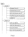
- FIG. 2 shows a part of a directory structure of a DVD system.
- FIG. 2 shows a directory structure of real time recording (RTR) DVD of the DVD system, and a directory structure of an audio file.
- RTR real time recording
- directories for respective standards exist, and directory names are "VIDEO_TS” in DVD-video, "AUDIO_TS” in DVD-audio, and "DVD_RTAV” in RTR-DVD.
- FIG. 2 shows "DVD_RTAV” and "AUDIO_TS”. Recorded data exists in each directory.
- the data is stored in a normal file form in the DVD.
- a title corresponds, for example, to one movie, and a plurality of titles can be recorded on one disc.
- a group of titles is called a title set, and the title set is constituted of a plurality of files.
- VMG video manager
- the DVD-video title set includes video title set information (VTSI) for managing the title set, and is constituted of the VTSI, video file constituted of video data, and a backup of the VTSI.
- VTSI video title set information
- VMG disc information
- VTSI title set
- VMGI new video manager information
- VR_MANGR.IFO as a video manager (VMG) file
- VR_MOVIE as a movie video file
- VR_STILL.VRO as a still picture video file
- VR_AUDIO.VRO as a still picture audio video file
- VR_MANAGR.BUP as a backup of video manager
- AUDIO_TS.IFO as an audio manager information (AMGI) file
- AUDIO_TS.BUP as an audio manager information (AMGI) backup file
- ATS_01_0.IFO as an audio title set information (ATSI) file
- ATS_01_0.AOB as an audio title set (ATS) audio object file
- Navigation data is recorded in the VR_MANEGER.IFO file, and is data for advancing a program set, program, entry point, play list, and the like.
- the VR_MOVIE.VRO file is a so-called movie AV file for recording a movie video object (movie VOB).
- the VR_STILL.VRO is a still picture AV file for recording a still picture VOB.
- the VR_AUDIO.VRO is a still picture additional audio file for recording an additional audio stream for a still picture.
- the VR_MOVIE.VRO is used to record an original VOB constituted of a video part including an arbitrary sub picture unit. Moreover, in this case, an audio part associated with the video part is also included in the original VOB.
- the VR_AUDIO.VRO is a file for use in recording the additional audio part, and the additional audio part indicates an audio stream recorded by after-recording.
- the audio part recorded in the VR_AUDIO.VRO is used in combination with several video parts recorded in the VR_STILL.VRO.
- the VR_MANGR.BUP is a backup file of VR_MANGR.IFO.
- FIG. 3A shows a file structure of VR_MOVIE.VRO as the movie video file.
- the video file has a hierarchical structure, one file is constituted of a plurality of video objects (VOB), one VOB is constituted of a plurality of video object units (VOBU), and one VOBU is constituted of a plurality of packs.
- the plurality of packs include an RDI pack, V pack, A pack, and the like.
- the V pack is constituted by compressing video data in an MPEG2 system, and is constituted of a pack header, packet header, and video data section.
- the A pack is constituted by processing the audio data, for example, by a linear PCM, MPEG, or AC3 system, and is constituted of a pack header, packet header, and audio data section.
- FIG. 3B shows data in the V pack and a format of video data based on the MPEG2 system.
- a group of pictures is a compressed unit using a plurality of video frames, and a sequence header is added to the top of the unit.
- a start code (SHC) of the sequence header a start code (SHC) of the sequence header, number (HS) of longitudinal lines of a pixel, number (VS) of lateral lines of the pixel, aspect ratio (PAR), and the like are described.
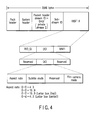
- An RDI pack shown in FIG. 4 is a real time data information pack (RDI_PCK), and includes real time general information (RDI_GI), display control information (DCI), manufacturer information (MNFI), and the like.
- RDI_PCK real time data information pack
- RDI_GI real time general information
- DCI display control information
- MNFI manufacturer information
- the real time general information includes information indicating a start time for reproducing a first field of VOBU to which the information belongs, that is, VOBU_S_PTM, and information indicating a recording time of the VOBU, that is, VOBU_REC_TM.
- the display control information includes information (DCI_SS) indicating statuses of display control information (DCI), and display control information (DCI) itself.
- the display control information status (DCI_SS) in (DCI_SS) is a first area, and a case (01b) in which only effective aspect ratio information exists, and a case (11b) in which an effective aspect ratio, subtitle mode, and film camera mode exist are identified.
- the display control information includes aspect ratio information, subtitle mode information, and film camera mode.
- the aspect ratio information indicates an aspect ratio of 4:3 (000b), and aspect ratio of 16:9 (0001b). Furthermore, when a source picture is a letter box, 1000b (letter box (14:9) disposed in a screen center), 0100b (letter box (14:9) disposed in a screen top), 1101b (letter box (16:9) disposed in the screen center), 0010b (letter box (16:9) disposed in the screen top), 1010b (letter box (>16:9) disposed in the screen center), and 0111b (14:9, full format, disposed in the center) are identified.
- a subtitle which does not open (00b), a subtitle which is in an active image area (01b), and a subtitle which is outside the active image area (10b) are identified.
- a data reproducing order recorded in the video file is defined by a program chain (PGC).
- PPC program chain
- a cell is defined in the program chain (PGC)
- VOB as an object to be reproduced is defined in the cell.
- a portion in which concrete information of PGC is recorded is a program chain information (PGCI) portion of VMG file.
- PGCI program chain information
- ORG_PGCI original PGCI
- U_PGCIT user defined PGC table
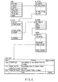
- a reproducing processing in the recording/ reproducing apparatus shown in FIG. 1 is performed according to PGCI, a plurality of programs can be designated in PGC, and the cell is defined in the program. Moreover, VOB as the object to be reproduced is designated by the cell. Moreover, a special PGC for reproducing the object in order of recording is referred to as an original PGC, and information of the original PGC is recorded as ORG_PGCI. Furthermore, attribute information of the video data (resolution information, aspect information, sound attribute information, and the like) is recorded in stream information (STI) in VMGI. Additionally, the pack is a minimum unit for performing a data transfer processing. Moreover, a minimum unit for performing a logic processing is a cell unit, and the logic processing is performed by the unit. Therefore, during recording, a recording signal is converted to a form which is compatible with the aforementioned format.
- the information recording/reproducing apparatus comprises: a hard disk drive 2001; a disc drive 35 for rotating/driving an optical disc 1001 as an information storage medium which can construct a video file, and reading/writing information with respect to the optical disc 1001; an encoder section 50 constituting a recording side; a decoder section 60 constituting a reproducing side; and a microcomputer block 30 for controlling the whole operation of the apparatus as main constituting elements.
- the encoder section 50 comprises: an analog-to-digital converter (ADC) 52; an encoder group 53 including a video (V) encoder, audio (A) encoder, and sub picture (SP) encoder; a formatter 56 for setting an output of each encoder to a predetermined format; and a buffer memory 57.
- ADC analog-to-digital converter
- V video
- A audio
- SP sub picture
- an external analog video signal + external analog audio signal from an AV input section 42, or an analog video signal + analog sound signal from a television (TV) tuner 44 are inputted.
- the ADC 52 digitizes the inputted analog video signal, for example, while a sampling frequency is 13.5 MHz and number of quantizing bits is eight. That is, a luminance component Y, color-difference component Cr (or Y-R) and color-difference component Cb (or Y-B) are quantized with eight bits, respectively.
- the ADC 52 digitizes the inputted analog audio signal, for example, while the sampling frequency is 48 kHz and the number of quantizing bits is 16.
- the digital video signal or the digital audio signal is inputted to the ADC 52, the digital video signal or the digital audio signal is passed through the ADC 52. Moreover, a jitter reduction processing, sampling rate change processing, and the like may also be performed with respect to these digital video and audio signals without changing contents.
- the digital video signal outputted from the ADC 52 is sent to the formatter 56 via the V encoder.
- the digital audio signal outputted from the ADC 52 is sent to the formatter 56 via the A encoder.
- the V encoder has a function for converting the inputted digital video signal to a compressed digital signal at a variable bit rate based on the MPEG2 or MPEG1 standard.
- the A encoder has a function for converting the inputted digital audio signal to the digital signal compressed at a fixed bit rate or a digital signal of a linear PCM based on the MPEG or AC-3 standard.
- the sub picture signal (sub picture pack) in the DVD video signal is inputted to the SP encoder.
- the sub picture signal inputted to the SP encoder is arranged into a predetermined signal mode, and sent to the formatter 56.
- the formatter 56 uses the buffer memory 57 as a work area to perform a predetermined signal processing with respect to the inputted video signal, audio signal, sub picture signal, and the like. Thereby, the recorded data which is compatible with the format (file structure) described above with reference to FIGS. 3 and 4 is outputted to a data processor 36.
- the present apparatus can supply the information encoded by the encoder section 50, and prepared management information to the hard disk drive 2001 via the data processor 36, and record the information on a hard disk. Moreover, the information recorded on the hard disk can also be recorded on the optical disc 1001 via the data processor 36 and disc drive 35. Furthermore, the information encoded by the encoder section 50, and prepared management information can be recorded on the optical disc 1001 via the data processor 36 and disc drive 35.
- the information recorded on the hard disk of the hard disk apparatus 2001 has the same data format as that of the optical disc 1001
- the information of the hard disk can be recorded on the optical disc without any encode processing.
- the encoder section 50 encodes the information read from the hard disk. Subsequently, the encoded information can be recorded on the optical disc 1001.
- the encode processed main picture data, audio data and sub picture data are combined, and converted to a structure of video object set VOBS.
- the cell is set as the minimum unit of the main picture data (video data), and cell information is prepared as shown in FIG. 5. Subsequently, the constitution of the cell constituting the program chain PGC, and main picture, sub picture and audio attributes are set (information obtained during encoding of the respective data is utilized as a part of these attribute information), and here a VMG file including various information is prepared.
- the encode-processed main picture data, audio data and sub picture data are finely divided into constant-size (2048 bytes) packs (FIG. 3). A dummy pack is appropriately inserted into these packs. Additionally, time stamps such as a presentation time stamp (PTS) indicating a reproducing time, and a decoding time stamp (DTS) indicating a decoding time are described in the pack other than the dummy pack. For PTS of the sub picture, the main picture data of the same reproducing time zone, or an arbitrarily delayed time from PTS of the audio data can be described.
- PTS presentation time stamp
- DTS decoding time stamp
- RDI pack (corresponding to a navigation pack) is disposed on top of the unit of the video object unit VOBU and the respective cells are disposed so that the respective data can be reproduced in order of a time code.
- a video object set VOBS constituted of one or more video objects VOB is recorded in the movie video file.
- a section for executing reading/writing (recording and/or reproducing) of the information with respect to the optical disc 1001 comprises the disc drive 35 having optical and driving systems, the data processor 36, a temporary storage 37, and a system time counter or a system time clock (STC) 38.
- STC system time clock
- the temporary storage 37 is utilized to buffer a constant amount of data written into the optical disc 1001 via the data processor 36 and disc drive 35 (data outputted from the encoder section 50), or buffer a constant amount of data reproduced from the optical disc 1001 via the disc drive 35 and data processor 36 (data inputted to the decoder section 60).
- the disc drive 35 includes a rotation control system, laser driving system, optical system, and the like for the optical disc.
- the temporary storage 37 when the temporary storage 37 is constituted of a 4 Mbyte semiconductor memory (DRAM), it is possible to buffer the recorded or reproduced data for about eight seconds at a recording rate of 4 Mbits per second (Mbps) on average. Moreover, when the temporary storage 37 is constituted of a 16 Mbyte electrically erasable and programmable (EEP) flash memory (ROM), it is possible to buffer the recorded or reproduced data for about 30 seconds at a recording rate of 4 Mbps on average.
- DRAM 4 Mbyte semiconductor memory
- EEP electrically erasable and programmable
- the temporary storage 37 is constituted of a 100 Mbyte micro hard disk drive (HDD), it is possible to buffer the recorded or reproduced data for three minutes or more at the recording rate of 4 Mbps on average.
- HDD micro hard disk drive
- the temporary storage 37 can also be utilized to temporarily store the recorded information for a short time until replacement of the optical disc 1001 with a new disc, when the optical disc 1001 is used up during recording.
- the hard disk drive 2001 having a large capacity is disposed, this drive can be utilized.
- the temporary storage 37 can also be utilized to temporarily store the data excessively read from a usual drive in a constant time, when a high-speed drive (double or more speed) is employed as the disc drive 35.
- a high-speed drive double or more speed
- the reproduced data buffered in the temporary storage 37 is changed/used, and the reproduced picture can be prevented from being interrupted.
- the data processor 36 follows control of the microcomputer block 30 to supply DVD recorded data outputted from the encoder section 50 to the disc drive 35, extract DVD reproduced signal reproduced from he optical disc 1001 from the disc drive 35, rewrite the management information recorded on the optical disc 1001, or to delete the data (file or video object) recorded on the optical disc 1001.
- the microcomputer block 30 includes a microprocessing unit (MPU) or a central processing unit (CPU), ROM with control program written therein, and RAM for providing a work area necessary for executing the program.
- MPU microprocessing unit
- CPU central processing unit
- ROM read-only memory
- RAM random access memory
- the MPU of the microcomputer block 30 follows the control program stored in the ROM and uses the RAM as the work area to execute detection of a defective place, detection of an unrecorded area, setting of a video recorded information recording position, UDF recording, and setting of an AV address.
- the microcomputer block 30 has an information processing section necessary for controlling the whole system, and includes a copy information detector/setter, directory detector, and VMG management information generator.
- a content to be notified to a user of the disc drive 35 is displayed in a display 48 of the DVD video recorder, or on-screen displayed (OSD) on a monitor display.
- OSD on-screen displayed
- timings of the microcomputer block 30 for controlling the disc drive 35, data processor 36, encoder section 50 and/or decoder section 60, and the like can be determined based on time data from the STC 38.
- a recording or reproducing operation is usually executed in synchronization with a time clock from the STC 38, but other processings may be executed at a timing independent of the STC 38.
- the decoder section 60 comprises: a separator 62 for separating and extracting each pack from picture information having the pack structure shown in FIG. 3; a memory 63 for use in separating the pack or executing other signal processing; a decoder group 64 including a V decoder for decoding main picture data (content of the video pack) separated by the separator 62, SP decoder for decoding sub picture data (content of the sub picture pack) separated by the separator 62, and A decoder for decoding audio data (content of the audio pack) separated by the separator 62; and a video processor 66 for appropriately combining the main picture data obtained from the V decoder with the sub picture data obtained from the SP decoder, and superposing and outputting sub pictures such as menu, highlight button, and subtitle on the main picture.
- a decoder group 64 including a V decoder for decoding main picture data (content of the video pack) separated by the separator 62, SP decoder for decoding sub picture data (content of the sub picture pack) separated
- An output of the video processor 66 is inputted to a video mixer 71.
- the video mixer 71 text data is synthesized.
- the video mixer 71 is also connected to a line for directly extracting the signal from the TV tuber 44 and A/V input section 42.
- the video mixer 71 is connected to a frame memory 72 for use as a buffer.
- the video mixer 71 emits a digital output, the output is transmitted to the outside via an interface (I/F) 73.
- An analog output of the mixer is outputted to the outside via a DAC 74.
- the output is transmitted to the outside via an interface (I/F) 75.
- An analog output of the decoder is analog-converted by a DAC 77 via a selector 76 and outputted to the outside.
- the selector 76 can also select the output from the ADC 52, when the signal from the TV tuber 44 or the A/V input section 42 is directly monitored in response to a select signal from the microcomputer block 30.
- An analog audio signal is supplied to a not-shown external component (multichannel (two to six channels) stereo apparatus).
- an inputted AV signal is digital-converted by the ADC 52.
- the video signal is inputted to the V encoder, the audio signal is inputted to the A encoder, and character data such as character broadcasting is inputted to the SP encoder.
- the video signal is subjected to MPEG compression, the audio signal is subjected to AC3 or MPEG audio compression, and the character data is subjected to run length compression.
- the compressed data from each encoder is packeted to indicate 2048 bytes in a packed state, and inputted to the formatter 56.
- each packet is packed, further multiplexed, and sent to the data processor 36.
- the formatter 56 prepares RDI pack based on the information from an aspect information detector 43, and disposes the pack on the top of the video object unit (VOBU).
- VOBU video object unit
- the data processor 36 forms ECC block for every 16 packs, attaches error correction data, and records the output into the optical disc 1001 via the disc drive 35.
- the output is stored in the temporary storage 37 (e.g., HDD buffer section), until DVD-RAM drive section (disc drive 35) is prepared.
- the temporary storage 37 e.g., HDD buffer section
- the formatter 56 prepares each segmenting information, and periodically sends the information to the MPU of the microcomputer block 30 (information of a time for GOP top interruption).
- Examples of the segmenting information include the number of packs of VOBU, end address of one picture from the top of VOBU, reproducing time of VOBU, and the like.
- the information from the aspect information detector 43 is sent to the MPU at the start of recording, and the MPU prepares VOB stream information (STI).
- STI VOB stream information
- resolution data, aspect data, and the like are stored, and each decoder performs initial setting based on the information during reproducing.
- one file is stored in one video in video reproducing DVD.
- a contiguous sector is necessary at minimum for accessing the data in order to reproduce the data without being interrupted during accessing (seeking). This unit is called a contiguous data area (CDA).
- CDA contiguous data area
- the CDA preferably has an ECC block unit. Therefore, a CDA size is a multiple of 16 sectors, and the data is recorded by the CDA unit in the file system. Additionally, in this case, when there is no vacant area fit for the size of CDA in the disc, a short sector used by another file is permitted to enter the CDA. Thereby, it is possible to record the data by the CDA unit.
- the apparatus has a time slip (TS) function.
- TS time slip
- the hard disk drive 2001 is effectively utilized. That is, the hard disk drive 2001 records the information on air from the A/V input section or the TV tuner into the hard disk. While this recording is continued, the recorded information may be read, decoded and monitored. Alternatively, it is possible to record the information read from the hard disk in the optical disc 1001. Moreover, while the recorded information is decoded and monitored, it is possible to record the information being monitored in the hard disk.
- the hard disk drive 2001 is built into the apparatus, and the optical disc 1001 is removable and can freely be changed by the user.
- FIG. 8 mainly shows a function of recording data in the hard disk during a time slip operation.
- the microcomputer block 30 determines writing address and length of the data for use in the hard disk drive 2001, and issues a writing command via the data processor 36.
- the microcomputer block 30 checks whether or not there is an interrupt for extracting the segmenting information. Subsequently, if there is an interrupt, the segmenting information is taken from the formatter 56 (steps A8, A9). It is next checked whether or not there is input information of a time slip end key. With no information, it is checked whether or not the recorded data for one CDA as the next recording unit is accumulated in the formatter 56 (returning to step A6 from step A12).
- the encoder section 50 receives the aspect information from the AV input section 42, and sets the information (by the V encoder) in the sequence header (see FIG. 3B) of the MPEG video data according to an aspect information code. Furthermore, the same information is also set to the RDI pack in the formatter.
- a recorded video storage mode is set (step A13).
- the recorded data of the hard disk is deleted, and recorded data address information is deleted from the work RAM.
- the segmenting information is also deleted from the work RAM, and the processing ends (steps A14, A15).
- the recorded data address information is information prepared in the step A11.
- step A13 When the recorded video storage mode is confirmed in the step A13, the processing shifts to a recorded data storage processing of step A16.
- An operation flow of recording/storing processing is shown in detail in FIG. 9.
- interrupt information When interrupt information is detected, a factor for the interrupt is checked, the data for one pack is transferred to the data processor 36, and the number of recorded packs starts to be counted up. Moreover, every time one piece of segmenting information is taken for the pack successively processed by the formatter 56, an interrupt flag is set. This processing is performed until the interrupt is canceled. When the interrupt is canceled, the processing shifts to the step A9. It is then judged from the number of recorded packs whether or not there is data for one CDA. Moreover, the interrupt flag is simultaneously deleted. Therefore, even when the interrupt processing is executed, the segmenting information for preparing the cell, VOBU, PG, PGC, and the like is not lost.
- FIG. 9 shows a content of the step A16 of FIG. 7 in detail.
- a recorded data storage flow is indicated as a flow operated after the time slip end key is pressed.
- the microcomputer block 30 takes the segmenting information from the formatter 56, and initializes the encoder section. Moreover, the area of the data to be stored (or transferred) is determined from the recorded data address information (step B1).
- the area of the data to be stored (or transferred) is determined by the information selected by the user who views a reproducing screen as described later. Alternatively, the area may be determined by an automatic storing (or transferring) function of automatically storing (or transferring) all data subjected to time slip recording.
- a processing method for the data to be stored (or transferred) differs with recording media such as DVD-RAM, and hard disk. Therefore, it is judged whether the recording medium is designated as DVD-RAM or hard disk (step B2).
- an address of VOBU as an object to be recorded is checked from the segmenting information (step B3). It is then checked whether there is an RDI pack (step B4). With presence of the RDI pack, information indicating whether the RDI pack can be copied is checked. It is therefore judged whether or not the pack can be copied (step B5). When there is no RDI pack, and copying is permitted, the VOBU data having the address read based on the address of the VOBU is stored (step B6).
- step B7 it is checked whether the area of the data to be recorded (stored) ends.
- the processing returns to the step B3 to check the address of the VOBU as the next object from the segmenting information.
- the steps B4 to B7 are repeatedly executed.
- step B7 an operation of registering the VOBU's to be stored in the file system in the hard disk is performed according to the recorded data address information (step B8). That is, the management information of the image data of VMG of the hard disk is updated, so that the VOBU to be stored can be managed by the management information. Furthermore, image data reproducing information (cell, and the like) is further added after original PGC. Additionally, the segmenting information is utilized to add video object information (VOBI) such as search pointer.
- VOBI video object information
- the management data for the recorded data is updated, prepared, and added, and a real recording state is obtained in which the recorded VOB data is stored as it is.
- an area for recording data to be temporarily recorded on the hard disk (or a buffer area for the time slip) is provided.
- the portion of the buffer area used to store this recorded data is removed from the designation as the buffer area for time slip, so that this recorded data becomes archives.
- a supplementary buffer area is added to compensate for the decrease in the buffer area for time slip.
- the area of the recorded data to be temporarily recorded on the hard disk (buffer area for time slip) is secured.
- the image data to be stored may be copied in a position different from the buffer area for time slip. In this case, it is unnecessary to correct the buffer area for time slip.
- step B9 When DVD is designated as the recording medium in the step B2, data for each VOBU is read (step B9), and presence/absence of RDI pack is checked (step B10). When the RDI pack exists, copy enable/disable information is checked (step B11).
- the VOBU read in the step B9 is selected from the image data recorded on the hard disk, and specified when the user designates desired image data in the step B1.
- the read VOBU is stored in the DVD-RAM. It is judged with respect to the recorded data of the hard disk whether or not the area of the data to be recorded (transferred) is ended (step B13). When the area is ended (yes at step B13), the processing advances to step B14.
- the management information of the VOBU to be stored is registered in the file system of DVD-RAM based on the recorded data address information. That is, the management information of the image data in the video manager (VMG) of DVD-RAM is updated. Furthermore, image data reproducing information (cell, and the like) is added after the original PGC. Additionally, the segmenting information is utilized to add the video object information such as search pointer (VOBI).
- FIG. 10 is a flow chart showing a reproducing operation to which the operation flow can be shifted, for example, by monitor operation or reproducing operation performed during the time slip.
- step C3 initial setting of the decoder section 60 is performed (steps C1, C2). Subsequently, data to be reproduced in the recorded data on a hard disk side is determined, and an address for starting reproducing is determined by the address information and segmenting information (step C3).
- step C4 The flow next shifts to a cell reproducing processing (step C4), and reproducing is performed. It is next checked whether or not the reproducing ends (step C5). When cell reproducing does not end, the next cell is determined (step C6), and the cell reproducing processing is continued. On the other hand, the cell reproducing ends, and it is then checked whether the reproducing is ended by an error (step C7). When the error is a read error, a reproducing end processing is performed and the flow returns to start. When there is no error, the flow shifts to other processing during reproducing end, and ends.
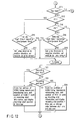
- FIGS. 11, 12 show a content of the cell reproducing processing in the step C4 of FIG. 10 in detail.
- a start entry point (EP(LBN)) and end entry point of the cell are determined (start EP, end EP) in accordance with contents of program chain information (PGCI) and time map information (TMAPI).
- the cell start entry point is set as a read entry point.
- a remaining cell length is obtained by subtracting a start address from an end address (step D1).
- step D2 the start address and reading length of CDA to be read are set (step D2). It is next judged whether CDA length is smaller than a remaining cell length (step D3).
- the remaining cell length can be updated (step D4).
- a reading command is set to the drive 35 based on the length of CDA to be read (step D6).
- the present reading length is set to the remaining cell length, and the updated remaining cell length is set to 0 (step D5).
- step D6 When the reading command is set to the drive 35 (step D6), transfer is started (step D7). It is next judged whether or not a seamless connection flag is set (step D8).
- the seamless connection flag is included as seamless information (SMLI) in M_VOBU, and indicates whether or not the reproducing is to be performed in a seamless manner with respect to the previous VOB.
- step D10 it is judged whether or not the transfer ends. However, in the seamless state, the read length is added to the read entry point, and the next read entry point is determined (step D9).
- step D12 key input is judged (step D12. With the key input, it is judged whether there is a fast-forward command (step D13) or a reverse command (step D14).
- the time slip and monitor are being performed. Therefore, it is judged whether the reproducing time (time slip reproducing position) is the same as a recording time (present recording position) (step D15). Alternatively, it is judged whether there is a certain degree of difference between the times.
- a jump direction is set to a positive direction
- a reading position is set in accordance with a jump amount, and the reproducing processing is performed by jumping to the reading position (step D17).
- step D16 it is judged whether a time slip start time (time slip recording start position) is the same as the recording time (present recording position) (step D16).
- the jump direction is set to a negative direction
- the reading position (reading file entry point; read_fp) is set in accordance with the jump amount
- the reproducing processing is performed by jumping to the reading position (step D18).
- This reading file entry point is determined based on the jump amount and time map information. That is, even with a large jump amount, when desired time information described in time map information is insufficient, the jump amount is automatically limited in order to avoid an inadvertently excess jump.
- the fast-forward and reverse operations performed in the reproducing during time slip have been described above.
- the recording operation is performed as follows.
- a recording start key is operated (step D21), a top address of VOBU being reproduced, reproducing time, and position of VOBI in a work are stored as recording (storage) start information (step D22), and the flow shifts to the step D10.
- a recording end key is operated (step D23), the top address of VOBU being reproduced, reproducing time, and position of VOBI in the work are stored as recording (storage) end information (step D24), and the flow shifts to the step D10.
- FIG. 13 shows a basic operation processing flow of the present apparatus.
- the apparatus is started, the encoder and decoder sections are initialized, and a command input from an operation key is waited for (steps E1, E2).
- a content of the command of the key input is interpreted (steps E3, E4), and the flow shifts to a time slip recording processing (step E5) and/or a reproducing processing (step E6).
- the recording processing and reproducing processing are performed in a time sharing manner for each disc, and the disc is processed in parallel.
- the reproducing processing includes a reproducing processing in a time slip mode and a usual reproducing processing.
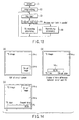
- FIG. 14A shows a situation in which a time slip image 14-a and on-air image 14-b are displayed on a monitor screen.
- time difference 14-c between on-air time (present time) and time slip image is displayed.
- the difference is numerically displayed as 20 minutes as shown in FIG. 14B.
- the time difference between an image reproduced by time slip and on-air image may be displayed by a time bar. That is, point P1 indicates an image point reproduced by the time slip, and point P2 indicates an on-air image point.
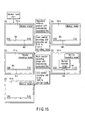
- FIG. 15A shows a screen example in the monitor mode during the time slip.
- a time bar BA is displayed.
- the image data recorded on the hard disk is reproduced, and the reproducing position is displayed, for example, as a movement mark MK with a different color midway in the time bar.
- the position of the movement mark MK can be moved to an arbitrary position on the time bar BA (FIG. 15B).
- a recording time of the recorded data by the time slip is displayed in minutes on the left end of the time bar BA.
- a shown example indicates that it takes two minutes to shift to a screen of FIG. 15B from FIG. 15A.
- FIG. 16 shows an example in which the movement mark MK is operated as described above, and two places (range RA1, RA2) are recorded.
- the recorded position setting is performed as a part of a key processing in the reproducing processing flow.
- information of a recording start or end position is stored in a work memory.
- the start position is set by a gap of VOBU. With no gap, the start position is set as a top or end address of VOBU to which the image belongs.
- the recording start (end) position information is information which indicates a recording area in the recording storage processing.
- the present invention comprises a first recording/reproducing medium (hard disk) for the time slip.
- a removable second recording/reproducing medium (recordable DVD, recordable/reproducible DVD, and the like) can be controlled.
- means for recording information in the first recording/reproducing medium and means for reproducing the recorded information with a time difference.
- means for recording information in the second recording/reproducing medium and means for reproducing the recorded information.
- display signal deriving means video processor, video mixer, digital/analog processor, interface, and the like
- system control means microcomputer block
- the time slip mode management information of the image data being recorded and monitored are monitored. As a result, a difference between the recording position (recording time) of the recorded image and the reproducing position (reproducing time) of the reproduced signal can be grasped.
- the difference is small based on the difference information, the key input of high-speed reverse is effective, but the high-speed forward is prohibited.
- both the high-speed reverse and the high-speed forward are effective.
- the hard disk is built into the apparatus in such a manner that the user cannot easily attach/detach the disc. Therefore, when the DVD system is combined as in the present invention, not only simple recording/ reproducing but also various utilization vales can be fulfilled. When the information temporarily recorded on the hard disk is transferred and stored in the DVD, a storage capacity of the hard disk can infinitely be utilized.
- the present invention is not limited to the aforementioned embodiment, and the format of DVD-RAM is employed in the encode system of the encoder section 30. However, this is not limited, and a desired program packet may be extracted from a digital broadcast signal and recorded as it is by a processing circuit. In this case, as the reproducing processing, decoding of the packet is performed once by a given decoder.
- DVD-RAM and another recordable medium are used together with the hard disk built in the apparatus.
- the function of the hard disk can effectively be utilized.
- the format recorded on the hard disk is set to be the same as formats of other recording media (DVD-RAM, and the like), the data read from the hard disk can easily be transferred and decoded.
Landscapes
- Engineering & Computer Science (AREA)
- Multimedia (AREA)
- Signal Processing (AREA)
- Signal Processing For Digital Recording And Reproducing (AREA)
- Management Or Editing Of Information On Record Carriers (AREA)
- Optical Recording Or Reproduction (AREA)
- Indexing, Searching, Synchronizing, And The Amount Of Synchronization Travel Of Record Carriers (AREA)
Abstract
Description
- The present invention relates to a recording/ reproducing apparatus which can simultaneously operate a plurality of recordable/reproducible mediums such as a hard disk(s), and recordable/reproducible digital versatile disc(s) (DVD).
- In recent years, optical disc players, for playing back optical discs with image, sound and other recorded data have been developed. These players, for LD or video CD, for example, have been widely utilized for the purpose of viewing movies, singing at Karaoke bars, etc.
- At present, a DVD standard has been proposed in which an internationally standardized moving image coding expert group (MPEG2) system is used, and further an AC3 audio compression system is employed.
- This DVD standard supports the MPEG2 scheme for a moving picture compression method according to the system layer of MPEG2, and also supports the AC3 audio compression scheme as well as the MPEG audio compression scheme for an audio compression method. Further, in this DVD standard, control data (Navigation pack) is additionally adapted so that a special reproduction such as a fast-forward or reverse reproduction etc. can be performed. Furthermore, in this DVD standard, the standard of IS09660 and Micro UDF is supported so that the data of a disc can be read by a computer.
- Moreover, as an own standard of media, subsequent to the standard of DVD-ROM which is the media of DVD-video, the standard of DVD-RAM (storage capacity of about 4.7GB) is also completed, and DVD-RAM drives are beginning to spread as computer peripherals.
- Additionally, at present, a DVD video standard which utilizes DVD-RAM and realizes a system capable of recording/reproducing information in real time, that is, a real time recording (RTR)-DVD standard is being completed, and a verification operation is also scheduled to end in the near future.
- The standard is developed based on the DVD video standard now on the market. Furthermore, a file system corresponding to the RTR-DVD is also standardized.
- On the other hand, a system is also considered in which a hard disk drive (HDD) built in the recording/reproducing apparatus is utilized to record/reproduce a broadcast signal. In the hard disk drive, data of 100 Gbytes or more can be recorded.
- When the hard disk drive and DVD system are individually considered, both have advantages and disadvantages.
- The hard disk drive is built into the recording/ reproducing apparatus in a normal use mode, and cannot be removed. Therefore, it is impossible to store data infinitely. The amount of recording space sometime runs short. Moreover, a user cannot easily remove the drive out of the recording/reproducing apparatus. Therefore, it is impossible to take out the disk and reproduce the data recorded on the disk with another apparatus.
- On the other hand, a recordable/reproducible DVD has a small storage capacity as compared with a hard disk. Moreover, it is impossible to record copy-protected information.
- An object of the present invention is to provide a recording/reproducing apparatus which can compensate for disadvantages of a DVD system and hard disk system, and can sufficiently derive advantages of the DVD system and hard disk system.
- To achieve the object, according to an embodiment of the present invention, there is provided a recording/reproducing apparatus comprising: a first recording/reproducing medium built into the apparatus for use as a temporary storage; a first recording/ reproducing section which can record information on or reproduce information from the first recording/ reproducing section; a second recording/reproducing section which can record information on or reproduce information from a second recording/reproducing medium; a display signal output section for supplying an external device with a reproduction signal from the first or second recording/reproducing section; and a system control section for controlling an operation of the apparatus.
- The apparatus may further comprise a section which composes input information, being subjected to recording processing of the first recording/reproducing section, with a reproduction signal, being reproduced by the first recording/reproducing section, to provide a result of composition, and outputs the composition result to the display signal output section, when a time slip command and monitor command are given to the system control section.
- This summary of the invention does not necessarily describe all necessary features so that the invention may also be a sub-combination of these described features.
- The invention can be more fully understood from the following detailed description when taken in conjunction with the accompanying drawings, in which:
- FIG. 1 is a diagram showing a basic constitution of a recording/reproducing apparatus according to an embodiment of the present invention.
- FIG. 2 is a diagram showing an example of a directory structure of a DVD.
- FIG. 3 is an explanatory view showing a video object set (VOBS) in a DVD standard, hierarchy of a data structure in an MPEG standard, and content of the hierarchy.
- FIG. 4 is an explanatory view of a RDI pack.
- FIG. 5 is an explanatory view showing a hierarchical structure of VMG in the DVD standard, particularly a hierarchical structure of a program chain.
- FIG. 6 is an explanatory view showing the hierarchical structure of VMG in the DVD standard, particularly a hierarchical structure of an AV file information table.
- FIG. 7 is a flowchart showing a recording operation of the apparatus according to the present invention.
- FIG. 8 shows a part of a flowchart.
- FIG. 9 is a flowchart showing a recorded data storage operation of the apparatus according to the present invention.
- FIG. 10 is a flowchart showing a cell reproducing operation in a reproducing operation in a time slip mode of the apparatus according to an embodiment of the present invention.
- FIG. 11 is a flowchart showing an operation during reproduction of a cell of FIG. 10.
- FIG. 12 is a flowchart continued from FIG. 11.
- FIG. 13 is an explanatory view showing the overall functional operations of the apparatus according to an embodiment of the present invention.
- FIG. 14 is an explanatory view showing a display example on a display screen in the time slip mode of the apparatus according to an embodiment of the present invention.
- FIG. 15 is an explanatory view continued from FIG. 14.
- FIG. 16 is an explanatory view continued from FIG. 15.
-
- An embodiment of the present invention will be described hereinafter with reference to the drawings.
- FIG. 1 is a diagram showing one embodiment of a recording/reproducing apparatus to which the present invention is applied. The blocks of FIG. 1 can be roughly divided into those of a recording section, shown on the left side, and those of a reproducing section, shown on the right side. The blocks of each section of FIG. 1 will be described later in detail.
- FIG. 2 shows a part of a directory structure of a DVD system. Particularly, FIG. 2 shows a directory structure of real time recording (RTR) DVD of the DVD system, and a directory structure of an audio file. In DVD, directories for respective standards exist, and directory names are "VIDEO_TS" in DVD-video, "AUDIO_TS" in DVD-audio, and "DVD_RTAV" in RTR-DVD. FIG. 2 shows "DVD_RTAV" and "AUDIO_TS". Recorded data exists in each directory.
- Moreover, the data is stored in a normal file form in the DVD. A title corresponds, for example, to one movie, and a plurality of titles can be recorded on one disc. Moreover, a group of titles is called a title set, and the title set is constituted of a plurality of files.
- Information for managing the disc information is recorded on one disc in DVD-video. The management information is recorded as a file, and referred to as a video manager (VMG).
- Furthermore, the DVD-video title set (VTS) includes video title set information (VTSI) for managing the title set, and is constituted of the VTSI, video file constituted of video data, and a backup of the VTSI.
- On the other hand, the information for managing the disc information (VMG) and information for managing the title set (VTSI) are unified in RTR-DVD, and defined as new video manager information (VMGI).
- In the directory "DVD-RTAV", respective files, that is, VR_MANGR.IFO as a video manager (VMG) file, VR_MOVIE as a movie video file, VR_STILL.VRO as a still picture video file, VR_AUDIO.VRO as a still picture audio video file, and VR_MANAGR.BUP as a backup of video manager exist.
- Moreover, in the directory "AUDIO_TS", AUDIO_TS.IFO as an audio manager information (AMGI) file, AUDIO_TS.BUP as an audio manager information (AMGI) backup file, ATS_01_0.IFO as an audio title set information (ATSI) file, and ATS_01_0.AOB as an audio title set (ATS) audio object file exist.
- Navigation data is recorded in the VR_MANEGER.IFO file, and is data for advancing a program set, program, entry point, play list, and the like.
- The VR_MOVIE.VRO file is a so-called movie AV file for recording a movie video object (movie VOB).
- The VR_STILL.VRO is a still picture AV file for recording a still picture VOB.
- Moreover, the VR_AUDIO.VRO is a still picture additional audio file for recording an additional audio stream for a still picture.
- The VR_MOVIE.VRO is used to record an original VOB constituted of a video part including an arbitrary sub picture unit. Moreover, in this case, an audio part associated with the video part is also included in the original VOB.
- The VR_AUDIO.VRO is a file for use in recording the additional audio part, and the additional audio part indicates an audio stream recorded by after-recording. The audio part recorded in the VR_AUDIO.VRO is used in combination with several video parts recorded in the VR_STILL.VRO.
- The VR_MANGR.BUP is a backup file of VR_MANGR.IFO.
- FIG. 3A shows a file structure of VR_MOVIE.VRO as the movie video file.
- The video file has a hierarchical structure, one file is constituted of a plurality of video objects (VOB), one VOB is constituted of a plurality of video object units (VOBU), and one VOBU is constituted of a plurality of packs. Examples of the plurality of packs include an RDI pack, V pack, A pack, and the like.
- The V pack is constituted by compressing video data in an MPEG2 system, and is constituted of a pack header, packet header, and video data section. The A pack is constituted by processing the audio data, for example, by a linear PCM, MPEG, or AC3 system, and is constituted of a pack header, packet header, and audio data section.
- FIG. 3B shows data in the V pack and a format of video data based on the MPEG2 system.
- A group of pictures (GOP) is a compressed unit using a plurality of video frames, and a sequence header is added to the top of the unit. In the sequence header, a start code (SHC) of the sequence header, number (HS) of longitudinal lines of a pixel, number (VS) of lateral lines of the pixel, aspect ratio (PAR), and the like are described.
- An RDI pack shown in FIG. 4 is a real time data information pack (RDI_PCK), and includes real time general information (RDI_GI), display control information (DCI), manufacturer information (MNFI), and the like.
- The real time general information (RDI_GI) includes information indicating a start time for reproducing a first field of VOBU to which the information belongs, that is, VOBU_S_PTM, and information indicating a recording time of the VOBU, that is, VOBU_REC_TM.
- The display control information (DCI) includes information (DCI_SS) indicating statuses of display control information (DCI), and display control information (DCI) itself.
- The display control information status (DCI_SS) in (DCI_SS) is a first area, and a case (01b) in which only effective aspect ratio information exists, and a case (11b) in which an effective aspect ratio, subtitle mode, and film camera mode exist are identified.
- The display control information (DCI) includes aspect ratio information, subtitle mode information, and film camera mode.
- The aspect ratio information indicates an aspect ratio of 4:3 (000b), and aspect ratio of 16:9 (0001b). Furthermore, when a source picture is a letter box, 1000b (letter box (14:9) disposed in a screen center), 0100b (letter box (14:9) disposed in a screen top), 1101b (letter box (16:9) disposed in the screen center), 0010b (letter box (16:9) disposed in the screen top), 1010b (letter box (>16:9) disposed in the screen center), and 0111b (14:9, full format, disposed in the center) are identified.
- In the subtitle mode, a subtitle which does not open (00b), a subtitle which is in an active image area (01b), and a subtitle which is outside the active image area (10b) are identified.
- In the film camera mode, a camera mode (0b), and film mode (1b) are identified.
- A data reproducing order recorded in the video file is defined by a program chain (PGC). A cell is defined in the program chain (PGC), and VOB as an object to be reproduced is defined in the cell. A portion in which concrete information of PGC is recorded is a program chain information (PGCI) portion of VMG file. There are two types of PGCI, one is original PGCI (ORG_PGCI), and the other is a user defined PGC table (UD_PGCIT).
- Turning back to FIG. 1, the recording/reproducing apparatus of the disc standardized as described above will be described.
- A reproducing processing in the recording/ reproducing apparatus shown in FIG. 1 is performed according to PGCI, a plurality of programs can be designated in PGC, and the cell is defined in the program. Moreover, VOB as the object to be reproduced is designated by the cell. Moreover, a special PGC for reproducing the object in order of recording is referred to as an original PGC, and information of the original PGC is recorded as ORG_PGCI. Furthermore, attribute information of the video data (resolution information, aspect information, sound attribute information, and the like) is recorded in stream information (STI) in VMGI. Additionally, the pack is a minimum unit for performing a data transfer processing. Moreover, a minimum unit for performing a logic processing is a cell unit, and the logic processing is performed by the unit. Therefore, during recording, a recording signal is converted to a form which is compatible with the aforementioned format.
- The information recording/reproducing apparatus comprises: a
hard disk drive 2001; adisc drive 35 for rotating/driving anoptical disc 1001 as an information storage medium which can construct a video file, and reading/writing information with respect to theoptical disc 1001; anencoder section 50 constituting a recording side; adecoder section 60 constituting a reproducing side; and amicrocomputer block 30 for controlling the whole operation of the apparatus as main constituting elements. - The
encoder section 50 comprises: an analog-to-digital converter (ADC) 52; anencoder group 53 including a video (V) encoder, audio (A) encoder, and sub picture (SP) encoder; aformatter 56 for setting an output of each encoder to a predetermined format; and abuffer memory 57. - To the
ADC 52, an external analog video signal + external analog audio signal from anAV input section 42, or an analog video signal + analog sound signal from a television (TV)tuner 44 are inputted. - The
ADC 52 digitizes the inputted analog video signal, for example, while a sampling frequency is 13.5 MHz and number of quantizing bits is eight. That is, a luminance component Y, color-difference component Cr (or Y-R) and color-difference component Cb (or Y-B) are quantized with eight bits, respectively. - Similarly, the
ADC 52 digitizes the inputted analog audio signal, for example, while the sampling frequency is 48 kHz and the number of quantizing bits is 16. - Additionally, when the digital video signal or the digital audio signal is inputted to the
ADC 52, the digital video signal or the digital audio signal is passed through theADC 52. Moreover, a jitter reduction processing, sampling rate change processing, and the like may also be performed with respect to these digital video and audio signals without changing contents. - The digital video signal outputted from the
ADC 52 is sent to theformatter 56 via the V encoder. Moreover, the digital audio signal outputted from theADC 52 is sent to theformatter 56 via the A encoder. - The V encoder has a function for converting the inputted digital video signal to a compressed digital signal at a variable bit rate based on the MPEG2 or MPEG1 standard. Moreover, the A encoder has a function for converting the inputted digital audio signal to the digital signal compressed at a fixed bit rate or a digital signal of a linear PCM based on the MPEG or AC-3 standard.
- When sub picture information is inputted from the AV input section 42 (e.g., signal from DVD video player with an independent output terminal of a sub picture signal), or when a DVD video signal having this data constitution is broadcast and received by the
TV tuner 44, the sub picture signal (sub picture pack) in the DVD video signal is inputted to the SP encoder. The sub picture signal inputted to the SP encoder is arranged into a predetermined signal mode, and sent to theformatter 56. - The
formatter 56 uses thebuffer memory 57 as a work area to perform a predetermined signal processing with respect to the inputted video signal, audio signal, sub picture signal, and the like. Thereby, the recorded data which is compatible with the format (file structure) described above with reference to FIGS. 3 and 4 is outputted to adata processor 36. - Here, the present apparatus can supply the information encoded by the
encoder section 50, and prepared management information to thehard disk drive 2001 via thedata processor 36, and record the information on a hard disk. Moreover, the information recorded on the hard disk can also be recorded on theoptical disc 1001 via thedata processor 36 anddisc drive 35. Furthermore, the information encoded by theencoder section 50, and prepared management information can be recorded on theoptical disc 1001 via thedata processor 36 anddisc drive 35. - Moreover, in the present invention, when the information recorded on the hard disk of the
hard disk apparatus 2001 has the same data format as that of theoptical disc 1001, the information of the hard disk can be recorded on the optical disc without any encode processing. - Furthermore, when the data format of the information recorded on the hard disk of the
hard disk drive 2001 is different from that of theoptical disc 1001, theencoder section 50 encodes the information read from the hard disk. Subsequently, the encoded information can be recorded on theoptical disc 1001. - Here, a standard encode processing for preparing the data to be recorded into the
optical disc 1001 will briefly be described. That is, when the encode processing starts in theencoder section 50, parameters necessary for subjecting video (main picture) data and audio data to the encode processing are set. - Subsequently, when the set parameter is used to subject the main picture data to a pre-encode processing, distribution of a code amount optimum for a set average transfer rate (recording rate) is calculated. The encode processing of the main picture data is executed based on the code amount distribution obtained by the pre-encode processing. In this case, the encode processing of the audio data is also executed. Similarly, a parameter necessary for subjecting the sub picture data to the encode processing is set, and the sub picture data subjected to the encode processing is prepared.
- The encode processed main picture data, audio data and sub picture data are combined, and converted to a structure of video object set VOBS.
- That is, the cell is set as the minimum unit of the main picture data (video data), and cell information is prepared as shown in FIG. 5. Subsequently, the constitution of the cell constituting the program chain PGC, and main picture, sub picture and audio attributes are set (information obtained during encoding of the respective data is utilized as a part of these attribute information), and here a VMG file including various information is prepared.
- The encode-processed main picture data, audio data and sub picture data are finely divided into constant-size (2048 bytes) packs (FIG. 3). A dummy pack is appropriately inserted into these packs. Additionally, time stamps such as a presentation time stamp (PTS) indicating a reproducing time, and a decoding time stamp (DTS) indicating a decoding time are described in the pack other than the dummy pack. For PTS of the sub picture, the main picture data of the same reproducing time zone, or an arbitrarily delayed time from PTS of the audio data can be described.
- Moreover, RDI pack (corresponding to a navigation pack) is disposed on top of the unit of the video object unit VOBU and the respective cells are disposed so that the respective data can be reproduced in order of a time code. This constitutes the video object VOB of a plurality of cells. A video object set VOBS constituted of one or more video objects VOB is recorded in the movie video file.
- Additionally, when a DVD reproducing signal is digitally copied from a DVD video player, the contents of the cell, program chain, management table, time stamp, and the like are predetermined, and it is therefore unnecessary to prepare these.
- A section for executing reading/writing (recording and/or reproducing) of the information with respect to the
optical disc 1001 comprises thedisc drive 35 having optical and driving systems, thedata processor 36, atemporary storage 37, and a system time counter or a system time clock (STC) 38. - The
temporary storage 37 is utilized to buffer a constant amount of data written into theoptical disc 1001 via thedata processor 36 and disc drive 35 (data outputted from the encoder section 50), or buffer a constant amount of data reproduced from theoptical disc 1001 via thedisc drive 35 and data processor 36 (data inputted to the decoder section 60). Thedisc drive 35 includes a rotation control system, laser driving system, optical system, and the like for the optical disc. - For example, when the
temporary storage 37 is constituted of a 4 Mbyte semiconductor memory (DRAM), it is possible to buffer the recorded or reproduced data for about eight seconds at a recording rate of 4 Mbits per second (Mbps) on average. Moreover, when thetemporary storage 37 is constituted of a 16 Mbyte electrically erasable and programmable (EEP) flash memory (ROM), it is possible to buffer the recorded or reproduced data for about 30 seconds at a recording rate of 4 Mbps on average. - Furthermore, when the
temporary storage 37 is constituted of a 100 Mbyte micro hard disk drive (HDD), it is possible to buffer the recorded or reproduced data for three minutes or more at the recording rate of 4 Mbps on average. - The
temporary storage 37 can also be utilized to temporarily store the recorded information for a short time until replacement of theoptical disc 1001 with a new disc, when theoptical disc 1001 is used up during recording. - However, in the apparatus according to an embodiment of the present invention, since the
hard disk drive 2001 having a large capacity is disposed, this drive can be utilized. - Moreover, the
temporary storage 37 can also be utilized to temporarily store the data excessively read from a usual drive in a constant time, when a high-speed drive (double or more speed) is employed as thedisc drive 35. When the data read during reproducing is buffered in thetemporary storage 37, and even when an optical head (not shown) causes a reading error by vibration shock, the reproduced data buffered in thetemporary storage 37 is changed/used, and the reproduced picture can be prevented from being interrupted. - The
data processor 36 follows control of themicrocomputer block 30 to supply DVD recorded data outputted from theencoder section 50 to thedisc drive 35, extract DVD reproduced signal reproduced from heoptical disc 1001 from thedisc drive 35, rewrite the management information recorded on theoptical disc 1001, or to delete the data (file or video object) recorded on theoptical disc 1001. - The
microcomputer block 30 includes a microprocessing unit (MPU) or a central processing unit (CPU), ROM with control program written therein, and RAM for providing a work area necessary for executing the program. - The MPU of the
microcomputer block 30 follows the control program stored in the ROM and uses the RAM as the work area to execute detection of a defective place, detection of an unrecorded area, setting of a video recorded information recording position, UDF recording, and setting of an AV address. - Moreover, the
microcomputer block 30 has an information processing section necessary for controlling the whole system, and includes a copy information detector/setter, directory detector, and VMG management information generator. - For an execution result of the MPU, a content to be notified to a user of the
disc drive 35 is displayed in adisplay 48 of the DVD video recorder, or on-screen displayed (OSD) on a monitor display. - Additionally, timings of the
microcomputer block 30 for controlling thedisc drive 35,data processor 36,encoder section 50 and/ordecoder section 60, and the like can be determined based on time data from theSTC 38. A recording or reproducing operation is usually executed in synchronization with a time clock from theSTC 38, but other processings may be executed at a timing independent of theSTC 38. - The
decoder section 60 comprises: aseparator 62 for separating and extracting each pack from picture information having the pack structure shown in FIG. 3; amemory 63 for use in separating the pack or executing other signal processing; adecoder group 64 including a V decoder for decoding main picture data (content of the video pack) separated by theseparator 62, SP decoder for decoding sub picture data (content of the sub picture pack) separated by theseparator 62, and A decoder for decoding audio data (content of the audio pack) separated by theseparator 62; and avideo processor 66 for appropriately combining the main picture data obtained from the V decoder with the sub picture data obtained from the SP decoder, and superposing and outputting sub pictures such as menu, highlight button, and subtitle on the main picture. - An output of the
video processor 66 is inputted to avideo mixer 71. In thevideo mixer 71, text data is synthesized. Moreover, thevideo mixer 71 is also connected to a line for directly extracting the signal from theTV tuber 44 and A/V input section 42. Thevideo mixer 71 is connected to aframe memory 72 for use as a buffer. When thevideo mixer 71 emits a digital output, the output is transmitted to the outside via an interface (I/F) 73. An analog output of the mixer is outputted to the outside via aDAC 74. - When the A decoder emits the digital output, the output is transmitted to the outside via an interface (I/F) 75. An analog output of the decoder is analog-converted by a
DAC 77 via aselector 76 and outputted to the outside. Theselector 76 can also select the output from theADC 52, when the signal from theTV tuber 44 or the A/V input section 42 is directly monitored in response to a select signal from themicrocomputer block 30. An analog audio signal is supplied to a not-shown external component (multichannel (two to six channels) stereo apparatus). - A flow of a video signal in the aforementioned apparatus will briefly be described hereinafter.
- First, an inputted AV signal is digital-converted by the
ADC 52. The video signal is inputted to the V encoder, the audio signal is inputted to the A encoder, and character data such as character broadcasting is inputted to the SP encoder. The video signal is subjected to MPEG compression, the audio signal is subjected to AC3 or MPEG audio compression, and the character data is subjected to run length compression. - The compressed data from each encoder is packeted to indicate 2048 bytes in a packed state, and inputted to the
formatter 56. In theformatter 56, each packet is packed, further multiplexed, and sent to thedata processor 36. - Here, the
formatter 56 prepares RDI pack based on the information from an aspect information detector 43, and disposes the pack on the top of the video object unit (VOBU). - The
data processor 36 forms ECC block for every 16 packs, attaches error correction data, and records the output into theoptical disc 1001 via thedisc drive 35. - Here, with the
disc drive 35 in a busy state for seeking or track jump, the output is stored in the temporary storage 37 (e.g., HDD buffer section), until DVD-RAM drive section (disc drive 35) is prepared. - Furthermore, during recording, the
formatter 56 prepares each segmenting information, and periodically sends the information to the MPU of the microcomputer block 30 (information of a time for GOP top interruption). - Examples of the segmenting information include the number of packs of VOBU, end address of one picture from the top of VOBU, reproducing time of VOBU, and the like.
- Additionally, the information from the aspect information detector 43 is sent to the MPU at the start of recording, and the MPU prepares VOB stream information (STI). Here, for the STI, resolution data, aspect data, and the like are stored, and each decoder performs initial setting based on the information during reproducing.
- Moreover, for the video file, one file is stored in one video in video reproducing DVD.
- Here, in a real time video reproducing machine using DVD, it should be noted that a contiguous sector is necessary at minimum for accessing the data in order to reproduce the data without being interrupted during accessing (seeking). This unit is called a contiguous data area (CDA).
- The CDA preferably has an ECC block unit. Therefore, a CDA size is a multiple of 16 sectors, and the data is recorded by the CDA unit in the file system. Additionally, in this case, when there is no vacant area fit for the size of CDA in the disc, a short sector used by another file is permitted to enter the CDA. Thereby, it is possible to record the data by the CDA unit.
- The apparatus according to an embodiment of the present invention has a time slip (TS) function.
- Therefore, the
hard disk drive 2001 is effectively utilized. That is, thehard disk drive 2001 records the information on air from the A/V input section or the TV tuner into the hard disk. While this recording is continued, the recorded information may be read, decoded and monitored. Alternatively, it is possible to record the information read from the hard disk in theoptical disc 1001. Moreover, while the recorded information is decoded and monitored, it is possible to record the information being monitored in the hard disk. - The
hard disk drive 2001 is built into the apparatus, and theoptical disc 1001 is removable and can freely be changed by the user. - Here, the recording and reproducing functions of the whole apparatus according to an embodiment of the present invention will be described.
- FIG. 8 mainly shows a function of recording data in the hard disk during a time slip operation.
- Here, with respect to the meaning of the time slip operation, there are:
- the time slip operation is activated, for example, by a timer recording reservation function, or by a time slip recording operation, so that an external input signal is encoded and recorded on the whole hard disk or on the preset buffer area, to thereby achieve rewinding and playing back of the on-air program having been recorded; and
- the time slip operation is activated to achieve
a playback of the recorded data during the recording
operation.
- (a) The file system of the optical disc (DVD-RAM) is checked. If there is no file system, the file system is constructed.
- (b) The directory of the DVD-RAM is checked. If there is no real time recording (RTR) directory, the directory is prepared.
- (c) The video manager information (VMGI) is read into the work RAM from the DVD-RAM. If there is no information, the information is generated inside, and a VMGI table is constructed (this step is not shown). The processing (a), (b), (c) is a so-called preprocessing performed mainly by the microcomputer block 30.In the processing, while the DVD-RAM is inserted in the recording/reproducing apparatus, the file system, or the vacant area is checked. When the file system already exists, the data is read (steps A1, A2). Additionally, here, it is assumed that the hard disk is initialized. Subsequently, the VMG is prepared, and a writing processing is performed in a management area (step A3).
- (d) A recording initial setting is performed with
respect to the
encoder section 50, and recording is started/set (step A4). That is, themicrocomputer block 30 confirms a state in which recording is possible, and then performs recording initial setting. Furthermore, to reset the STC, set a writing start address to each drive, set a writing command, initially set the formatter, and set an align processing, division (segmenting information) of the cell, VOB, VOBU, program (PG), and program chain (PGC) is prepared/set. - (e) Furthermore, at the start of recording, a
recording command is set to the
encoder section 50, and the segmenting information in theformatter 56 is registered as VOB, VOBU (step A5). Thereby, when the recording starts, the frame of the input video signal is compressed by a GOP unit, the GOP is packed, and the packs are collected into a VOBU unit in theencoder section 50. Furthermore, aspect ratio information is inserted in the sequence header of GOP (see FIG. 3B). Moreover, the RDI pack is disposed as the top pack of VOBU (see FIGS. 3B and 4). In this case, as shown in FIG. 3A, the audio pack, sub picture pack, and the like are collected. The segmenting information indicates each group of the aforementioned data. - (f) When one CDA of encoded data is accumulated,
the data is set to each drive section and recorded in
the vacant area of the
hard disk drive 2001, and link information of the sector to be recorded is stored in the work RAM (A6). - (g) When the segmenting information is
accumulated in the
formatter 56, the segmenting information is read and taken as the VOB and VOBU management information in the work RAM, and steps (e) to (g) are repeated until issuance of a time slip end command (steps A7, A8, A9, A10, A11). - That is, when one CDA (recording unit) of data is collected, the
microcomputer block 30 determines writing address and length of the data for use in thehard disk drive 2001, and issues a writing command via thedata processor 36. - Moreover, the
microcomputer block 30 checks whether or not there is an interrupt for extracting the segmenting information. Subsequently, if there is an interrupt, the segmenting information is taken from the formatter 56 (steps A8, A9). It is next checked whether or not there is input information of a time slip end key. With no information, it is checked whether or not the recorded data for one CDA as the next recording unit is accumulated in the formatter 56 (returning to step A6 from step A12). - Here, the
encoder section 50 receives the aspect information from theAV input section 42, and sets the information (by the V encoder) in the sequence header (see FIG. 3B) of the MPEG video data according to an aspect information code. Furthermore, the same information is also set to the RDI pack in the formatter. - With operation of a time slip mode cancel key (step A12), it is judged whether or not a recorded video storage mode is set (step A13). When the recorded video storage mode is not set, the recorded data of the hard disk is deleted, and recorded data address information is deleted from the work RAM. Moreover, the segmenting information is also deleted from the work RAM, and the processing ends (steps A14, A15). The recorded data address information is information prepared in the step A11.
- When the recorded video storage mode is confirmed in the step A13, the processing shifts to a recorded data storage processing of step A16. An operation flow of recording/storing processing is shown in detail in FIG. 9.
- Prior to description of the operation flow of FIG. 9, a processing for an interrupt in the step A8 of FIG. 7 will briefly be described with reference to FIG. 8.
- When interrupt information is detected, a factor for the interrupt is checked, the data for one pack is transferred to the
data processor 36, and the number of recorded packs starts to be counted up. Moreover, every time one piece of segmenting information is taken for the pack successively processed by theformatter 56, an interrupt flag is set. This processing is performed until the interrupt is canceled. When the interrupt is canceled, the processing shifts to the step A9. It is then judged from the number of recorded packs whether or not there is data for one CDA. Moreover, the interrupt flag is simultaneously deleted. Therefore, even when the interrupt processing is executed, the segmenting information for preparing the cell, VOBU, PG, PGC, and the like is not lost. - FIG. 9 shows a content of the step A16 of FIG. 7 in detail.
- A recorded data storage flow is indicated as a flow operated after the time slip end key is pressed.
- In the recorded data storage flow, the
microcomputer block 30 takes the segmenting information from theformatter 56, and initializes the encoder section. Moreover, the area of the data to be stored (or transferred) is determined from the recorded data address information (step B1). - The area of the data to be stored (or transferred) is determined by the information selected by the user who views a reproducing screen as described later. Alternatively, the area may be determined by an automatic storing (or transferring) function of automatically storing (or transferring) all data subjected to time slip recording.
- A processing method for the data to be stored (or transferred) differs with recording media such as DVD-RAM, and hard disk. Therefore, it is judged whether the recording medium is designated as DVD-RAM or hard disk (step B2).
- When the recording medium is designated as the hard disk, an address of VOBU as an object to be recorded (stored) is checked from the segmenting information (step B3). It is then checked whether there is an RDI pack (step B4). With presence of the RDI pack, information indicating whether the RDI pack can be copied is checked. It is therefore judged whether or not the pack can be copied (step B5). When there is no RDI pack, and copying is permitted, the VOBU data having the address read based on the address of the VOBU is stored (step B6).
- Subsequently, it is checked whether the area of the data to be recorded (stored) ends (step B7). When the area of the data to be recorded (stored) does not end, the processing returns to the step B3 to check the address of the VOBU as the next object from the segmenting information. The steps B4 to B7 are repeatedly executed.
- When the data area to be recorded (stored) ends (yes at step B7), an operation of registering the VOBU's to be stored in the file system in the hard disk is performed according to the recorded data address information (step B8). That is, the management information of the image data of VMG of the hard disk is updated, so that the VOBU to be stored can be managed by the management information. Furthermore, image data reproducing information (cell, and the like) is further added after original PGC. Additionally, the segmenting information is utilized to add video object information (VOBI) such as search pointer.
- Therefore, when the user designates the area of the data to be recorded (stored) from the video data recorded on the hard disk by the time slip in the recording mode, a storage object is determined, and real recording is performed.
- In the aforementioned description, in order to store the recorded data, the management data for the recorded data is updated, prepared, and added, and a real recording state is obtained in which the recorded VOB data is stored as it is.
- However, the invention is not limited to the aforementioned embodiment, and the following function may be further provided. That is, an area for recording data to be temporarily recorded on the hard disk (or a buffer area for the time slip) is provided. When the recorded data in the buffer area is to be stored as described above, the portion of the buffer area used to store this recorded data is removed from the designation as the buffer area for time slip, so that this recorded data becomes archives. In this case, a supplementary buffer area is added to compensate for the decrease in the buffer area for time slip.
- Alternatively, the following system may be used.
- That is, the area of the recorded data to be temporarily recorded on the hard disk (buffer area for time slip) is secured. Moreover, when the recorded image data is stored in the buffer area as described above, the image data to be stored may be copied in a position different from the buffer area for time slip. In this case, it is unnecessary to correct the buffer area for time slip.
- Turning back to FIG. 9, the operation flow will be described.
- When DVD is designated as the recording medium in the step B2, data for each VOBU is read (step B9), and presence/absence of RDI pack is checked (step B10). When the RDI pack exists, copy enable/disable information is checked (step B11).
- The VOBU read in the step B9 is selected from the image data recorded on the hard disk, and specified when the user designates desired image data in the step B1.
- When the copy enable/disable information of the RDI pack indicates permission for copying, the read VOBU is stored in the DVD-RAM. It is judged with respect to the recorded data of the hard disk whether or not the area of the data to be recorded (transferred) is ended (step B13). When the area is ended (yes at step B13), the processing advances to step B14. In the step B14, the management information of the VOBU to be stored is registered in the file system of DVD-RAM based on the recorded data address information. That is, the management information of the image data in the video manager (VMG) of DVD-RAM is updated. Furthermore, image data reproducing information (cell, and the like) is added after the original PGC. Additionally, the segmenting information is utilized to add the video object information such as search pointer (VOBI).
- FIG. 10 is a flow chart showing a reproducing operation to which the operation flow can be shifted, for example, by monitor operation or reproducing operation performed during the time slip.
- First, initial setting of the
decoder section 60 is performed (steps C1, C2). Subsequently, data to be reproduced in the recorded data on a hard disk side is determined, and an address for starting reproducing is determined by the address information and segmenting information (step C3). - The flow next shifts to a cell reproducing processing (step C4), and reproducing is performed. It is next checked whether or not the reproducing ends (step C5). When cell reproducing does not end, the next cell is determined (step C6), and the cell reproducing processing is continued. On the other hand, the cell reproducing ends, and it is then checked whether the reproducing is ended by an error (step C7). When the error is a read error, a reproducing end processing is performed and the flow returns to start. When there is no error, the flow shifts to other processing during reproducing end, and ends.
- FIGS. 11, 12 show a content of the cell reproducing processing in the step C4 of FIG. 10 in detail.
- A start entry point (EP(LBN)) and end entry point of the cell are determined (start EP, end EP) in accordance with contents of program chain information (PGCI) and time map information (TMAPI). The cell start entry point is set as a read entry point. A remaining cell length is obtained by subtracting a start address from an end address (step D1).
- Moreover, the start address and reading length of CDA to be read are set (step D2). It is next judged whether CDA length is smaller than a remaining cell length (step D3).
- Subsequently, when the CDA length is smaller, and the length of the CDA to be read is subtracted from the remaining cell length, the remaining cell length can be updated (step D4). Moreover, a reading command is set to the
drive 35 based on the length of CDA to be read (step D6). When the length of the CDA to be read is larger than the remaining cell length in the step D4, the present reading length is set to the remaining cell length, and the updated remaining cell length is set to 0 (step D5). - When the reading command is set to the drive 35 (step D6), transfer is started (step D7). It is next judged whether or not a seamless connection flag is set (step D8). The seamless connection flag is included as seamless information (SMLI) in M_VOBU, and indicates whether or not the reproducing is to be performed in a seamless manner with respect to the previous VOB.
- In a non-seamless state, it is judged whether or not the transfer ends (step D10). However, in the seamless state, the read length is added to the read entry point, and the next read entry point is determined (step D9).
- At the end of the transfer, it is judged whether or not the remaining cell length is 0. When the remaining cell length is 0, the flow shifts to the step C4 of FIG. 11. When there is a remaining cell length, the flow returns to the step D2. When the transfer does not end in the step D10, key input is judged (step D12. With the key input, it is judged whether there is a fast-forward command (step D13) or a reverse command (step D14).
- With the fast-forward command, the time slip and monitor are being performed. Therefore, it is judged whether the reproducing time (time slip reproducing position) is the same as a recording time (present recording position) (step D15). Alternatively, it is judged whether there is a certain degree of difference between the times. When a condition for the fast-forward is obtained as a result of judgment, a jump direction is set to a positive direction, a reading position (reading file entry point; read_fp) is set in accordance with a jump amount, and the reproducing processing is performed by jumping to the reading position (step D17).
- Moreover, with the reverse command, it is judged whether a time slip start time (time slip recording start position) is the same as the recording time (present recording position) (step D16). When a condition for the reverse is obtained as the result of judgment, the jump direction is set to a negative direction, the reading position (reading file entry point; read_fp) is set in accordance with the jump amount, and the reproducing processing is performed by jumping to the reading position (step D18). This reading file entry point is determined based on the jump amount and time map information. That is, even with a large jump amount, when desired time information described in time map information is insufficient, the jump amount is automatically limited in order to avoid an inadvertently excess jump.
- The fast-forward and reverse operations performed in the reproducing during time slip (monitor mode) have been described above. The recording operation is performed as follows.
- As shown in FIG. 12, a recording start key is operated (step D21), a top address of VOBU being reproduced, reproducing time, and position of VOBI in a work are stored as recording (storage) start information (step D22), and the flow shifts to the step D10. Moreover, a recording end key is operated (step D23), the top address of VOBU being reproduced, reproducing time, and position of VOBI in the work are stored as recording (storage) end information (step D24), and the flow shifts to the step D10.
- FIG. 13 shows a basic operation processing flow of the present apparatus.
- The apparatus is started, the encoder and decoder sections are initialized, and a command input from an operation key is waited for (steps E1, E2). When there is a key input, a content of the command of the key input is interpreted (steps E3, E4), and the flow shifts to a time slip recording processing (step E5) and/or a reproducing processing (step E6). Subsequently, the recording processing and reproducing processing are performed in a time sharing manner for each disc, and the disc is processed in parallel. The reproducing processing includes a reproducing processing in a time slip mode and a usual reproducing processing.
- These reproducing processing contents are selected and determined in accordance with a key operation state. When the reproducing operation of the monitor mode is performed in the time slip mode, a time-slipped recorded image is reproduced. Moreover, in this case, when a sub screen display and on-air display key is selected, a screen is obtained as shown in FIG. 14A. FIG. 14A shows a situation in which a time slip image 14-a and on-air image 14-b are displayed on a monitor screen.
- Furthermore, when the reproducing operation is performed in the time slip mode, the time-slipped recorded image is reproduced. Subsequently, when operation input of time difference display is performed, time difference 14-c between on-air time (present time) and time slip image is displayed. For example, the difference is numerically displayed as 20 minutes as shown in FIG. 14B. Alternatively, as shown in FIG. 14C, the time difference between an image reproduced by time slip and on-air image may be displayed by a time bar. That is, point P1 indicates an image point reproduced by the time slip, and point P2 indicates an on-air image point.
- FIG. 15A shows a screen example in the monitor mode during the time slip. In this case, for example, a time bar BA is displayed. Moreover, in the monitor screen, the image data recorded on the hard disk is reproduced, and the reproducing position is displayed, for example, as a movement mark MK with a different color midway in the time bar.
- In this case, when a high-speed forward or reverse operation is performed, the position of the movement mark MK can be moved to an arbitrary position on the time bar BA (FIG. 15B). A recording time of the recorded data by the time slip is displayed in minutes on the left end of the time bar BA. A shown example indicates that it takes two minutes to shift to a screen of FIG. 15B from FIG. 15A.
- When a recording operation is next performed in a time slip state, an edge MK1 of the movement mark MK is fixed onto the time bar, the movement mark MK moves with time on the time bar, and a monitor recorded range RA1 is indicated as shown in FIGS. 15C and 15D. Here, when a stop operation is performed, the range RA1 does not extend as shown in FIG. 15E. Subsequently, the movement mark MK appears. This means that an image of the division shown by the range RA1 is recorded (DVD) or stored (HDD). Furthermore, in this case, the mode shifts to the monitor mode. When the reproducing of the time slip advances, the movement mark MK moves on the time bar. In this case, for the movement mark MK, when the high-speed forward or reverse operation is performed as described above, the position of the movement mark MK can be moved to the arbitrary position on the time bar BA.
- FIG. 16 shows an example in which the movement mark MK is operated as described above, and two places (range RA1, RA2) are recorded.
- Additionally, the recorded position setting is performed as a part of a key processing in the reproducing processing flow. In the processing, information of a recording start or end position is stored in a work memory. The start position is set by a gap of VOBU. With no gap, the start position is set as a top or end address of VOBU to which the image belongs.
- When a setting other than the gap is permitted as the division setting (i.e., when a portion other than the gap is permitted as the reproducing starting or end position), the data is encoded again in the recording start position. For the recording end position, a processing of reproducing up to a designated frame and not reproducing subsequent frames needs to be performed. Moreover, a sequence code is attached to a last position, and the subsequent frame data (data of and after the recording end position) is deleted. The recording start (end) position information is information which indicates a recording area in the recording storage processing.
- As described above, the present invention comprises a first recording/reproducing medium (hard disk) for the time slip. Moreover, a removable second recording/reproducing medium (recordable DVD, recordable/reproducible DVD, and the like) can be controlled. Moreover, there are provided means for recording information in the first recording/reproducing medium, and means for reproducing the recorded information with a time difference. Furthermore, there are provide means for recording information in the second recording/reproducing medium, and means for reproducing the recorded information. These recording/reproducing means are realized by controlling the encoder and decoder sections.
- Moreover, there is provided display signal deriving means (video processor, video mixer, digital/analog processor, interface, and the like) for supplying the reproducing signal from the reproducing means to the display. Moreover, there is provided system control means (microcomputer block) for controlling the whole. Here, when the first recording means shifts to the time slip mode for performing the recording processing, the input information is encoded, and the recording processing of the first recording processing means is continued. Additionally, the position different from the recording position is reproduced by the first reproducing processing means, and the processing information can be supplied to the display signal deriving means. Moreover, in the reproducing information, the on-air image is combined and displayed as a sub screen.
- Furthermore, in the time slip mode, management information of the image data being recorded and monitored are monitored. As a result, a difference between the recording position (recording time) of the recorded image and the reproducing position (reproducing time) of the reproduced signal can be grasped. When the difference is small based on the difference information, the key input of high-speed reverse is effective, but the high-speed forward is prohibited. Moreover, when the difference is sufficient, both the high-speed reverse and the high-speed forward are effective.
- The hard disk is built into the apparatus in such a manner that the user cannot easily attach/detach the disc. Therefore, when the DVD system is combined as in the present invention, not only simple recording/ reproducing but also various utilization vales can be fulfilled. When the information temporarily recorded on the hard disk is transferred and stored in the DVD, a storage capacity of the hard disk can infinitely be utilized.
- Additionally, the present invention is not limited to the aforementioned embodiment, and the format of DVD-RAM is employed in the encode system of the
encoder section 30. However, this is not limited, and a desired program packet may be extracted from a digital broadcast signal and recorded as it is by a processing circuit. In this case, as the reproducing processing, decoding of the packet is performed once by a given decoder. - Moreover, various operations in the aforementioned apparatus are realized by operating a cursor operation lever, mode selection key, jog dial, and various other keys in a remote control apparatus.
- As described above, according to one embodiment of the present invention, DVD-RAM and another recordable medium are used together with the hard disk built in the apparatus. In this constitution, the function of the hard disk can effectively be utilized.
- Moreover, when the format recorded on the hard disk is set to be the same as formats of other recording media (DVD-RAM, and the like), the data read from the hard disk can easily be transferred and decoded.
Claims (16)
- A recording/reproducing apparatus characterized by comprising:a first recording/reproducing medium (2001);first recording/reproducing processing means (36, 37, 50, 60) for recording information on or reproducing information from said first recording/reproducing medium (2001);second recording/reproducing processing means (35-37, 50, 60) for recording information on or reproducing information from a second recording/reproducing medium (1001);display signal output means (73, 74) for supplying an external device with a reproduction signal from at least one of said first (36, 37, 50, 60) and second (35-37, 50, 60) recording/reproducing processing means;system control means (30) for controlling an operation of the apparatus; andmeans (71) for composing input information, being subjected to recording processing (HDD recording) of said first recording/reproducing processing means (36, 37, 50), with a reproduction signal (HDD reproduction), being reproduced by said first recording/reproducing processing means (36, 37, 60), to provide a result of composition, and outputting the composition result to said display signal output means (73, 74).
- A recording/reproducing apparatus according to claim 1, characterized in that said first recording/ reproducing medium (2001) is formed of a temporary storage medium (HDD and/or temporary memory) which is installed in the apparatus.
- A recording/reproducing apparatus according to claim 1 or 2, characterized in that a data recording format (e.g., HDD recording format) of said first recording/reproducing medium (2001) has a same structure as a data recording format (e.g., DVD-RAM recording format) of said second recording/reproducing medium (1001).
- A recording/reproducing apparatus according to any one of claims 1 to 3, characterized in that, if a time slip mode (C1 of FIG. 10) is activated in response to a given time slip instruction signal, said system control means (30) enables a fast forward (FF) operation when a time difference between a recording time (recording position) at which the input information is recorded and a reproducing time (reproduction time) of recorded information corresponding to the input information is equal to or less than a predetermined value (no at D15 of FIG. 12),and that the fast forward (FF) operation or a fast reverse (FR) operation is enabled (yes at D13, and yes at D14) when the time difference is larger than the predetermined value (no at D15, and no at D16).
- A recording/reproducing apparatus according to any one of claims 1 to 4, characterized in that, if a time slip mode (C1 of FIG. 10) is activated in response to a given time slip instruction signal, said system control means (30) enables a normal reproduction operation when a recording time (recording position) at which recording of the input information starts matches a reproducing time (reproduction time) of recorded information corresponding to the input information.
- A recording/reproducing apparatus according to any one of claims 1 to 5, characterized in that said input information includes image information, that when a time slip instruction signal is given (E3-E5 of FIG. 13), said system control means (30) supplies said display signal output means (73, 74) with the input information and reproduction information reproduced by said first recording/reproducing processing means (36, 37, 60), and that either of the input information and the reproduction information is displayed on a child screen (FIG. 14).
- A recording/reproducing apparatus according to any one of claims 1 to 6, characterized in that said input information includes image information,and that when a time slip instruction signal is given (E3-E5 of FIG. 13), said system control means (30)calculates (D15 or D16 of FIG. 12) a time difference between a recording screen of the input information and a reproducing screen which may be used for monitoring,generates (D22 or D24 of FIG. 12) a time bar or display text data corresponding to the calculated time difference, andsupplies the generated time bar or display text data to said display signal output means (73, 74).
- A recording/reproducing apparatus according to any one of claims 1 to 7, characterized in that said input information includes image information,that when a time slip instruction signal is given (E3-E5 of FIG. 13), said system control means (30) controls said first (36, 37, 50, 60) or second (35-37, 50, 60) recording/reproducing processing means such that when recording instruction information is given (E3 of FIG. 13), image data being currently reproduced is recorded on said first (2001) or second (1001) recording/reproducing medium,and that when time slip end information is given (E3 of FIG. 13), management information (FIG. 6) required to reproduce the recorded data is created (B1-B14 of FIG. 9), and the created management information is recorded on the corresponding recording/reproducing medium (2001 or 1001).
- A recording/reproducing apparatus according to claim 8, characterized in that said management information (FIG. 6) includes original program chain information (ORG_PGCI) as a part of video manager information.
- A recording/reproducing apparatus according to any one of claims 1 to 9, characterized in that said input information includes image information,and that when at least said second recording/reproducing processing means (35-37, 50, 60) encodes data output from said first recording/reproducing processing means (36, 37, 50, 60), and if the encoded data is to be recorded on said second recording/reproducing medium (1001), said system control means (30)discriminates copy control information contained in a predetermined unit (VOBU) of the encoded data (B5, B11 of FIG. 9),records the encoded data in the predetermined unit (VOBU) (B6, B12 of FIG. 9) only if a copy is allowed (yes at B5, yes at B11), andstops recording processing of said second recording/reproducing processing means (35-37, 50, 60) if the copy is inhibited (no at B5, no at B11).
- A recording/reproducing apparatus according to claim 10, characterized in that said predetermined unit (VOBU) is a unit including:a control pack (RDI pack of FIG. 3A) containing control data, said control pack being located at a head of the unit (VOBU), andone or more video packs (V packs of FIG. 3A) subsequent to the control pack.
- A recording/reproducing apparatus according to any one of claims 1 to 11, characterized in that said input information includes image information,and that when a time slip instruction signal is given (E3-E5 of FIG. 13), and if recording instruction information and recording time information are input (E3 of FIG. 13), said system control means (30)stops an output from said display signal output means (73, 74),controls said first (36, 37, 50, 60) or second (35-37, 50, 60) recording/reproducing processing means such that data of a currently reproduced image is recorded as a data file (FIG. 2) on said first (2001) or second (1001) recording/reproducing medium, andcreates (B8, B14 of FIG. 9), when recording is completed, management information (FIG. 6) required to reproduce the data recorded as the data file, wherein the created management information is recorded on the corresponding recording/reproducing medium (2001 or 1001).
- A recording/reproducing apparatus according to claim 12, characterized in that said data file (FIG. 2) is added to video object data, and that said management information (FIG. 6) includes a new program chain information (UD_PGCIT) to be added to an already existing original program chain information (ORG_PGCI).
- A recording/reproducing apparatus according to any one of claims 1 to 13, assuming that a time slip instruction signal is given (E3-E5 of FIG. 13), that recording time information as well as recording specifying information for specifying data to be stored from the recorded data are input, and that said first recording/reproducing medium (2001) is selected for storing the specified data,
characterized in that said system control means (30) excludes a portion of management for the specified data from management information (FIG. 6) recorded in a buffer area provided for a purpose of time slipping in said first recording/reproducing medium (2001),
and that a lack of the buffer area caused by the above exclusion is compensated for by other area of said first recording/reproducing medium (2001). - A recording/reproducing apparatus according to any one of claims 1 to 14, characterized in that a data format (e.g., DVD video recording format) of recording on said first recording/reproducing medium (2001) is selected to be equal to that of recording on said second recording/reproducing medium (1001),and that when data being recorded on said first recording/reproducing medium (2001) is recorded on said second recording/reproducing medium (1001), this recording is performed without a format conversion.
- A recording/reproducing method which can be used in an apparatus comprising a first recording/reproducing medium (2001); a first recording/reproducing processing section (36, 37, 50, 60) for recording information on or reproducing information from the first recording/reproducing medium (2001); a second recording/reproducing processing section (35-37, 50, 60) for recording information on or reproducing information from a second recording/ reproducing medium (1001); a display signal output section (73, 74) for supplying an external device with a reproduction signal from at least one of the first (36, 37, 50, 60) and second (35-37, 50, 60) recording/reproducing processing sections; a system control section (30) for controlling an operation of the apparatus,said method is characterized by comprising:composing input information, being subjected to recording processing (HDD recording) of said first recording/reproducing processing section (36, 37, 50), with a reproduction signal (HDD reproduction), being reproduced by said first recording/reproducing processing section (36, 37, 60), to provide a result of composition, andoutputting the composition result to said display signal output section (73, 74).
Applications Claiming Priority (2)
| Application Number | Priority Date | Filing Date | Title |
|---|---|---|---|
| JP2000300447A JP2002109831A (en) | 2000-09-29 | 2000-09-29 | Recording and playback device |
| JP2000300447 | 2000-09-29 |
Publications (2)
| Publication Number | Publication Date |
|---|---|
| EP1195766A2 true EP1195766A2 (en) | 2002-04-10 |
| EP1195766A3 EP1195766A3 (en) | 2004-08-18 |
Family
ID=18782133
Family Applications (1)
| Application Number | Title | Priority Date | Filing Date |
|---|---|---|---|
| EP01121657A Withdrawn EP1195766A3 (en) | 2000-09-29 | 2001-09-13 | Digital recording/reproducing apparatus |
Country Status (3)
| Country | Link |
|---|---|
| US (1) | US7224888B2 (en) |
| EP (1) | EP1195766A3 (en) |
| JP (1) | JP2002109831A (en) |
Cited By (2)
| Publication number | Priority date | Publication date | Assignee | Title |
|---|---|---|---|---|
| WO2005059910A1 (en) * | 2003-12-18 | 2005-06-30 | Matsushita Electric Industrial Co., Ltd. | Recording apparatus, integrated circuit for recording apparatus, recording method, computer program, and recording medium which facilitates content recording |
| EP1692598A4 (en) * | 2003-12-08 | 2007-05-16 | Sony Corp | MULTIMEDIA DOMESTIC NETWORK COMPUTER |
Families Citing this family (16)
| Publication number | Priority date | Publication date | Assignee | Title |
|---|---|---|---|---|
| JP2002170324A (en) * | 2000-11-30 | 2002-06-14 | Toshiba Corp | Internal storage media appendix |
| JP3825682B2 (en) * | 2001-11-09 | 2006-09-27 | 株式会社東芝 | Information recording apparatus and information processing apparatus for performing format conversion |
| KR100890305B1 (en) | 2001-11-29 | 2009-03-26 | 파나소닉 주식회사 | Recording device, recording medium and recording method |
| JP4224690B2 (en) * | 2002-12-27 | 2009-02-18 | ソニー株式会社 | Recording method, recording apparatus, reproducing method, reproducing apparatus, and imaging apparatus |
| JP2004220638A (en) * | 2003-01-09 | 2004-08-05 | Funai Electric Co Ltd | Video recording reproducing apparatus |
| JPWO2004102561A1 (en) * | 2003-05-13 | 2006-07-13 | 松下電器産業株式会社 | Content recording / reproducing apparatus and method |
| JP2005086480A (en) * | 2003-09-09 | 2005-03-31 | Funai Electric Co Ltd | Disk apparatus incorporated television receiver and reproducing apparatus incorporated television receiver |
| JP4269870B2 (en) * | 2003-10-02 | 2009-05-27 | ソニー株式会社 | Recording / reproducing apparatus and recording method |
| CN101534406B (en) * | 2004-03-31 | 2011-08-10 | 松下电器产业株式会社 | Video recording device for recording variable frame rate |
| JP4358081B2 (en) * | 2004-03-31 | 2009-11-04 | パナソニック株式会社 | Video recording device |
| US7471598B2 (en) | 2004-05-26 | 2008-12-30 | Nero Ag | Apparatus and method for copying data |
| JP4813370B2 (en) * | 2004-12-02 | 2011-11-09 | ソニー株式会社 | Video signal processing apparatus, video signal processing method, program, and recording medium |
| KR100691064B1 (en) * | 2005-04-18 | 2007-03-09 | 엘지전자 주식회사 | Navigation information recording method of optical disc |
| JP2007280447A (en) * | 2006-04-03 | 2007-10-25 | Toshiba Corp | Video / audio playback apparatus and video / audio playback method |
| KR101537702B1 (en) * | 2009-03-02 | 2015-07-20 | 엘지전자 주식회사 | Method of generating video file of video recording apparatus and video recording apparatus |
| JP5493531B2 (en) * | 2009-07-17 | 2014-05-14 | 三菱電機株式会社 | Video / audio recording / reproducing apparatus and video / audio recording / reproducing method |
Family Cites Families (16)
| Publication number | Priority date | Publication date | Assignee | Title |
|---|---|---|---|---|
| US5107481A (en) * | 1988-03-16 | 1992-04-21 | Matsushita Electric Industrial Co., Ltd. | Recording area management system for writable type optional disk |
| JPH06342580A (en) | 1993-05-31 | 1994-12-13 | Sony Corp | Editing device |
| US5438423C1 (en) * | 1993-06-25 | 2002-08-27 | Grass Valley Us Inc | Time warping for video viewing |
| US5701383A (en) * | 1994-05-20 | 1997-12-23 | Gemstar Development Corporation | Video time-shifting apparatus |
| JPH07336630A (en) | 1994-06-10 | 1995-12-22 | Hitachi Ltd | Video or audio recording / reproducing apparatus and video display system including the same |
| US6252732B1 (en) * | 1994-12-01 | 2001-06-26 | International Business Machines Corporation | Method and apparatus for correcting systematic errors in timing pattern generation |
| JP3435277B2 (en) | 1996-01-30 | 2003-08-11 | 株式会社東芝 | Copy protection device |
| CN1144455C (en) | 1996-02-08 | 2004-03-31 | 松下电器产业株式会社 | television receiver |
| US6005564A (en) * | 1996-12-05 | 1999-12-21 | Interval Research Corporation | Display pause with elastic playback |
| JP2956757B2 (en) | 1997-04-21 | 1999-10-04 | 日本電気株式会社 | Optical disk drive |
| JP4447669B2 (en) | 1997-04-25 | 2010-04-07 | ソニー株式会社 | Video display apparatus and method |
| US6480667B1 (en) | 1997-12-23 | 2002-11-12 | Intel Corporation | Method of time shifting to simultaneously record and play a data stream |
| JPH11328867A (en) | 1998-05-13 | 1999-11-30 | Sony Corp | Information recording medium, dubbing device, reproducing device, recording device, method for restricting duplication of information recording medium, method for collecting and distributing charges related to royalty, and network using the same |
| JP3107073B2 (en) | 1998-12-03 | 2000-11-06 | 日本電気株式会社 | Information recording and playback system |
| JP3715533B2 (en) * | 1999-02-05 | 2005-11-09 | 株式会社東芝 | Information storage medium for stream information, recording method, reproducing method, recording apparatus, and reproducing apparatus |
| CN100479512C (en) * | 1999-07-09 | 2009-04-15 | 松下电器产业株式会社 | Optical disc, and recorder, player, recording method and reproducing method therefor |
-
2000
- 2000-09-29 JP JP2000300447A patent/JP2002109831A/en active Pending
-
2001
- 2001-09-13 EP EP01121657A patent/EP1195766A3/en not_active Withdrawn
- 2001-09-14 US US09/951,773 patent/US7224888B2/en not_active Expired - Fee Related
Non-Patent Citations (1)
| Title |
|---|
| No Search * |
Cited By (4)
| Publication number | Priority date | Publication date | Assignee | Title |
|---|---|---|---|---|
| EP1692598A4 (en) * | 2003-12-08 | 2007-05-16 | Sony Corp | MULTIMEDIA DOMESTIC NETWORK COMPUTER |
| US7734155B2 (en) | 2003-12-08 | 2010-06-08 | Sony Corporation | Multimedia home network computer |
| WO2005059910A1 (en) * | 2003-12-18 | 2005-06-30 | Matsushita Electric Industrial Co., Ltd. | Recording apparatus, integrated circuit for recording apparatus, recording method, computer program, and recording medium which facilitates content recording |
| CN1918646B (en) * | 2003-12-18 | 2010-05-26 | 松下电器产业株式会社 | Recording device, integrated circuit for recording device, recording method, computer program, and recording medium facilitating content recording |
Also Published As
| Publication number | Publication date |
|---|---|
| US20020041754A1 (en) | 2002-04-11 |
| US7224888B2 (en) | 2007-05-29 |
| EP1195766A3 (en) | 2004-08-18 |
| JP2002109831A (en) | 2002-04-12 |
Similar Documents
| Publication | Publication Date | Title |
|---|---|---|
| US7136573B2 (en) | Recording rate automatic setting recording device and recording rate automatic setting recording method | |
| US7212725B2 (en) | Recording/reproducing apparatus and picture recording reservation method of recording/reproducing apparatus | |
| US6577812B1 (en) | Digital recording system using variable recording rate | |
| US7289723B2 (en) | Digital recording system using variable recording rate | |
| JP3631430B2 (en) | Recording / playback device with automatic chapter creation function | |
| JP3677205B2 (en) | Information recording apparatus for multiple recording surfaces and information recording method for multiple recording surfaces | |
| CN100566399C (en) | recorder, replayer, record method and replay method | |
| US7224888B2 (en) | Digital recording/reproducing apparatus | |
| JP2004295947A (en) | Information recording medium, information recording / reproducing method, and information recording / reproducing device | |
| JP3637275B2 (en) | Information immediate recording apparatus and information immediate recording method | |
| JP3688573B2 (en) | Recording / playback device | |
| EP1213927B1 (en) | Digital recording/reproducing apparatus with built-in storage medium | |
| JP3607630B2 (en) | Video recording / reproducing method and apparatus for a plurality of recording media | |
| JP3631422B2 (en) | DVD recording / reproducing apparatus | |
| EP1206133A2 (en) | Recording device which handles recording reservations and recording method which handles recording reservations | |
| US8059938B2 (en) | Picture recording apparatus | |
| JP3607596B2 (en) | Recording / playback device with chapter creation guide function | |
| JP4071750B2 (en) | Recording / playback device with playlist creation guide function | |
| JP3981099B2 (en) | Recording rate automatic setting recording device | |
| JP4005989B2 (en) | DVD recording / reproducing method | |
| JP3987513B2 (en) | Video recording / reproducing apparatus and method for recording media | |
| JP2004364328A (en) | Information recording device | |
| JP2004274788A (en) | Recording device for recording reservation |
Legal Events
| Date | Code | Title | Description |
|---|---|---|---|
| PUAI | Public reference made under article 153(3) epc to a published international application that has entered the european phase |
Free format text: ORIGINAL CODE: 0009012 |
|
| 17P | Request for examination filed |
Effective date: 20010913 |
|
| AK | Designated contracting states |
Kind code of ref document: A2 Designated state(s): AT BE CH CY DE DK ES FI FR GB GR IE IT LI LU MC NL PT SE TR |
|
| AX | Request for extension of the european patent |
Free format text: AL;LT;LV;MK;RO;SI |
|
| PUAL | Search report despatched |
Free format text: ORIGINAL CODE: 0009013 |
|
| AK | Designated contracting states |
Kind code of ref document: A3 Designated state(s): AT BE CH CY DE DK ES FI FR GB GR IE IT LI LU MC NL PT SE TR |
|
| AX | Request for extension of the european patent |
Extension state: AL LT LV MK RO SI |
|
| 17Q | First examination report despatched |
Effective date: 20050323 |
|
| AKX | Designation fees paid |
Designated state(s): DE FR GB |
|
| RBV | Designated contracting states (corrected) |
Designated state(s): DE FR GB |
|
| STAA | Information on the status of an ep patent application or granted ep patent |
Free format text: STATUS: THE APPLICATION IS DEEMED TO BE WITHDRAWN |
|
| 18D | Application deemed to be withdrawn |
Effective date: 20100401 |