EP1195554A1 - Guide optique destiné à la transmission d'un faisceau d'ondes électromagnétiques à l'intérieur d'un appareil électroménager et appareil électroménager equipe d'un tel guide - Google Patents
Guide optique destiné à la transmission d'un faisceau d'ondes électromagnétiques à l'intérieur d'un appareil électroménager et appareil électroménager equipe d'un tel guide Download PDFInfo
- Publication number
- EP1195554A1 EP1195554A1 EP01420191A EP01420191A EP1195554A1 EP 1195554 A1 EP1195554 A1 EP 1195554A1 EP 01420191 A EP01420191 A EP 01420191A EP 01420191 A EP01420191 A EP 01420191A EP 1195554 A1 EP1195554 A1 EP 1195554A1
- Authority
- EP
- European Patent Office
- Prior art keywords
- guide
- base
- upper face
- household appliance
- projection
- Prior art date
- Legal status (The legal status is an assumption and is not a legal conclusion. Google has not performed a legal analysis and makes no representation as to the accuracy of the status listed.)
- Granted
Links
- 230000005540 biological transmission Effects 0.000 title claims description 12
- 230000003287 optical effect Effects 0.000 claims abstract description 14
- 238000005485 electric heating Methods 0.000 claims 1
- 230000002452 interceptive effect Effects 0.000 claims 1
- 239000000835 fiber Substances 0.000 abstract 2
- 238000010438 heat treatment Methods 0.000 description 16
- XLYOFNOQVPJJNP-UHFFFAOYSA-N water Substances O XLYOFNOQVPJJNP-UHFFFAOYSA-N 0.000 description 6
- 230000035515 penetration Effects 0.000 description 3
- 238000010586 diagram Methods 0.000 description 2
- 230000007935 neutral effect Effects 0.000 description 2
- 230000001105 regulatory effect Effects 0.000 description 2
- 238000009835 boiling Methods 0.000 description 1
- 238000010411 cooking Methods 0.000 description 1
- 230000000593 degrading effect Effects 0.000 description 1
- 230000008030 elimination Effects 0.000 description 1
- 238000003379 elimination reaction Methods 0.000 description 1
- 230000006870 function Effects 0.000 description 1
- 235000000396 iron Nutrition 0.000 description 1
- 238000000034 method Methods 0.000 description 1
- 230000004048 modification Effects 0.000 description 1
- 238000012986 modification Methods 0.000 description 1
- 230000005693 optoelectronics Effects 0.000 description 1
- 230000003647 oxidation Effects 0.000 description 1
- 238000007254 oxidation reaction Methods 0.000 description 1
- 238000005498 polishing Methods 0.000 description 1
- 229920000515 polycarbonate Polymers 0.000 description 1
- 239000004417 polycarbonate Substances 0.000 description 1
- 230000009993 protective function Effects 0.000 description 1
- 238000007789 sealing Methods 0.000 description 1
- 230000008054 signal transmission Effects 0.000 description 1
Images

Classifications
-
- G—PHYSICS
- G02—OPTICS
- G02B—OPTICAL ELEMENTS, SYSTEMS OR APPARATUS
- G02B6/00—Light guides; Structural details of arrangements comprising light guides and other optical elements, e.g. couplings
- G02B6/0001—Light guides; Structural details of arrangements comprising light guides and other optical elements, e.g. couplings specially adapted for lighting devices or systems
-
- G—PHYSICS
- G02—OPTICS
- G02B—OPTICAL ELEMENTS, SYSTEMS OR APPARATUS
- G02B6/00—Light guides; Structural details of arrangements comprising light guides and other optical elements, e.g. couplings
- G02B6/0001—Light guides; Structural details of arrangements comprising light guides and other optical elements, e.g. couplings specially adapted for lighting devices or systems
- G02B6/0011—Light guides; Structural details of arrangements comprising light guides and other optical elements, e.g. couplings specially adapted for lighting devices or systems the light guides being planar or of plate-like form
- G02B6/0013—Means for improving the coupling-in of light from the light source into the light guide
- G02B6/0015—Means for improving the coupling-in of light from the light source into the light guide provided on the surface of the light guide or in the bulk of it
- G02B6/002—Means for improving the coupling-in of light from the light source into the light guide provided on the surface of the light guide or in the bulk of it by shaping at least a portion of the light guide, e.g. with collimating, focussing or diverging surfaces
- G02B6/0021—Means for improving the coupling-in of light from the light source into the light guide provided on the surface of the light guide or in the bulk of it by shaping at least a portion of the light guide, e.g. with collimating, focussing or diverging surfaces for housing at least a part of the light source, e.g. by forming holes or recesses
Definitions
- the invention relates to the field of household appliances. It aims more precisely household appliances with a movable element removable from a base in which information must be transmitted from the movable part to the base. It relates more specifically to a guide optical allowing the transmission of information in optical form from the movable element to the base for a plurality of positions of the element movable relative to the base.
- the invention finds a very particular application for so-called “cordless” kettles, and therefore described in more detail for this application, but is in no way limited to it.
- the pot contains a heating element, typically a resistance electric, which when powered can heat the water contained in the pot.
- the heating resistance is supplied by a connector located at the contact area between the pot and the basement. This connector typically has three poles, namely a phase, neutral and earth.
- the heating control device When the heating control device is located in the base, it may be interesting to transmit information relating to the temperature of the water or the heating element, from the pot and plinth direction. This information allows for example to stop the heating when the boiling point has been reached, or when the heating element reaches a temperature such that it risks degrading or to degrade its neighborhood.
- a problem which the invention therefore proposes to solve is that of allow an optical transmission of a signal between the mobile part at pot and the base, while retaining the possibility of placing the pot on the base in a plurality of angular positions.
- the invention therefore relates to an optical guide which is intended for the transmission of a beam of electromagnetic waves inside a appliance.
- part of the transmitted beam is refracted towards outside the guide at the projection, regardless of the point of incidence of the incident beam on the upper face of the guide.
- the light beam or more generally the wave electromagnetic which carries the signal containing the information desired, can penetrate inside the guide at any point of the upper side.
- the beam which has entered the guide is reflected on the various walls of this guide, and is thus routed to the projection on the underside.
- the light-emitting diode or the like component which emits the representative beam of information can adopt a plurality of positions relative to the guide.
- This transmitter can be found in any point on the upper surface of the guide that forms a substantially circular crown.
- the receiver On the underside of the guide, therefore that the receiver is located in front of the projection, it must receive a fraction of the beam circulating inside the guide, regardless of the area through which the emitted beam entered the guide.
- the thickness of the guide measured between its upper and lower faces is increasing along the circumference of the guide, and has a discontinuity at the level of the projection.
- This break or the projection constitutes the fraction of the surface of the underside by which part of the transmitted ray leaves the guide.
- the underside of the guide can have the shape of a helical ramp, corresponding to a variation thickness proportional to the angle of travel of the circumference.
- the upper face of the guide is frosted, while the other faces of the guide are on the contrary polished.
- the frosting of the upper surface allows penetration of one of the incident beams for a large value range of the angle of incidence.
- the polishing of the other faces of the guide allows the beam transmitted inside the guide to be totally reflected on the walls it encounter during its journey to the projection.
- the upper face of the guide can further include radial grooves.
- the upper face presents with respect to the incident beam, zones forming different angles, facilitating the penetration of this incident beam.
- the lateral faces inner and outer connecting the upper and lower faces are cylindrical.
- the invention also relates to an apparatus household appliances comprising a mobile element capable of being put in place removably on a base while retaining a rotation capacity by report to said base in which the movable element comprises a resistance electric heater powered by an electric power source associated with the base, via a connector located in the contact area of the movable element and the base.
- the mobile element has a transmitter, which whatever either the angular position of the movable element relative to the base, is found in the eyes of the guide, since the latter has, seen from above, a circular geometry.
- the receiver located in the base has a fixed position and receives part of the beam emitted by the transmitter and transmitted by the guide.
- the transmission of the beam emitted was optimal when the maximum angle of incidence of the beam emitted by the emitter, measured with respect to a perpendicular to the upper face of the guide is between 60 ° and 80 °.
- the transmitted signal can be an alternating signal of variable duty cycle, depending on a quantity physics of part of the moving element, for example of the temperature of the water or the heating element when it is a kettle.
- the invention relates to an optical guide which can be used in particular in cordless kettles.
- FIG. 1 An example of such a kettle is illustrated in Figure 1.
- This kettle has a base (1) on which a pot can be placed removable (2).
- This pot has a gripping area (3).
- the pot (2) also includes a heating resistor (4) located at near the bottom of the pot.
- This heating resistor (4) is connected to a concentric connector (5), located on the pot area opposite the base (1).
- This concentric connector (5) has three poles, namely a phase, ground and neutral.
- This connector (5) allows the supply of the heating resistance (4) from the mains voltage.
- the base (1) includes a power cord (7).
- the base (1) comprises a module electronic (8) capable of regulating the supply of the electrical resistance (4), as well as a protective function.
- the module electronic (8) can thus supply the resistance heating (4) via a contactor (9) controlled so appropriate.
- the pot (2) is equipped with means specific electronics intended to ensure the optical transmission of a information about the temperature of the water (or the heating element of the pot), in the direction of the base, and intended for the regulation means (8).
- the electronic means (10) present on the pot have in the illustrated form an optoelectronic component (12) ensuring the emission of an infrared signal from the underside of the pot (2) towards the area opposite the base (1).
- the electronic means (10) on board the mobile pot may include an infrared diode (12) controlled by example by a signal with variable duty cycle.
- the duty cycle is variable depending on the resistance value of a thermistor located near the heating element, this thermistor being sensitive to water temperature as well as that of the heating element.
- the pot (2) is mounted on the base (1) of in such a way that the connector (5) is engaged regardless of the angular position of the pot (2) relative to the base.
- the base (1) comprises an optical guide particular (20), which allows the transmission of the signal emitted by the diode infrared (12) present under the pot, intended for a receiver (21) itself connected to the electronic regulation means (8) integrated in the base (1).
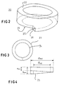
- the guide (20) placed in the base (1) is illustrated in Figures 2 to 4.
- Such a guide (20) has a geometry generally substantially annular. Its upper face (22), which has a circular crown shape is visible from above the base (1).
- the average diameter of the guide (20) corresponds substantially to the distance from which the infrared diode (12) of the pot is spaced relative to the axis (13) of this last. In other words, the infrared diode sits directly above the guide.
- the infrared diode (12) present under the pot is oriented in such a way so that the beam it emits has a certain incidence, close to 20 ° with respect to the upper face (22) of the guide. More precisely, the beam (15) emitted by the infrared diode is slightly conical, and the axis of revolution (16) of the cone forms an angle close to 70 ° with a perpendicular to the upper face (22) of the guide. The half opening angle of the cone is about 15 °.
- the upper side of the guide (22) is frosted to form micro-asperities which allow good refraction of the incident beam inside the guide. This refraction is further improved by the presence of radial micro grooves.
- Guide (20) has exterior and interior surfaces substantially cylindrical.
- the underside (25) of the guide illustrated in Figure 2 follows a shape of a helical ramp.
- the thickness of the guide i.e. the distance measured between the upper face (22) and the face lower (25) therefore varies gradually along the circumference of the guide.
- the underside (25) of the guide (20) has a discontinuity thick forming a projection (26).
- This projection (26) constitutes a pan inclined (27) substantially perpendicular to the underside (25) or the upper face (22).
- the lower faces (25) and upper (22) are not exactly parallel, but form between them, at least locally a slight angle.
- the guide has an outside diameter ⁇ ext of 58 millimeters and an inner diameter of 42 millimeters.
- the minimum thickness e min of the guide, at the level of the projection (26) is 10 millimeters and the maximum thickness e max , taking into account the projection (26) is 15 millimeters.
- the outer (23), inner (24) and lower (25) sides of the guide (20) are polished to ensure a regular surface finish, and allow the total reflection of the beam circulating inside the guide.
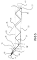
- Figure 5 illustrates an approximate path of several incident beams entering the guide from its face higher.
- a beam penetrates with a similar incidence (i) 70 °, in a first place (31) of the upper face (22) of the guide, it refracts inside the guide to give the beam (32). Then, this beam (32) reaches the underside (22) of the guide.
- the incidence (r) of this beam on the wall of the lower face (22) is sufficient high, the beam (32) is fully reflected to give the beam (33).
- this angle of incidence (r) must be greater than 42.16 °.
- the beam (33) continues to progress in the guide by reflecting on the exterior, interior, bottom and higher.
- FIG. 5 illustrates another beam (35), shown in dotted lines, which also reaches the receiver (40), although it enters the guide at another point of incidence (36).
- the receiver (40) integral with the base (1) receives a fraction of the light emitted from the pot (2).
- the information emitted by the pot representative of the temperature of water or the heating element, which can for example be coded as form of variable duty cycle, reaches the receiver and is therefore further analyzed, regardless of the position in which the pot is placed place on the base.
- the kettle or more generally the household appliances comprising a base and a movable part may include regulating means located in the base, and which function thanks to information emitted by the pot, without indexing of the angular position of the pot relative to the base. Consequently, electronic regulation means can be implemented in the base, which is not subjected to high temperatures, and for which the sealing constraints are less important than for the pot.
- the invention is described in more detail for its application to cordless kettles but it can also find a advantage in other types of household appliance such as including coffee makers, teapots, heated wax applicators, cooking appliances or irons.
Landscapes
- Physics & Mathematics (AREA)
- General Physics & Mathematics (AREA)
- Optics & Photonics (AREA)
- Cookers (AREA)
- Laser Surgery Devices (AREA)
- Electric Stoves And Ranges (AREA)
- Optical Measuring Cells (AREA)
- Optical Fibers, Optical Fiber Cores, And Optical Fiber Bundles (AREA)
- Optical Integrated Circuits (AREA)
- Light Guides In General And Applications Therefor (AREA)
- Endoscopes (AREA)
Abstract
Description
- une face supérieure sensiblement plane, destinée à recevoir un faisceau incident et en réfracter une partie à l'intérieur du guide en un faisceau transmis ;
- une face inférieure qui présente un ressaut formant un pan sensiblement perpendiculaire auxdites surfaces inférieures et supérieures.
- l'élément mobile comporte un émetteur d'une onde électromagnétique, apte à émettre un signal représentatif d'une grandeur physique d'une partie de l'élément mobile ;
- le socle comporte un guide optique tel que décrit ci-avant, dont la face supérieure est en regard de l'émetteur situé sur l'élément mobile, et un récepteur d'ondes électromagnétiques situé en regard du ressaut du guide.
Claims (9)
- Guide optique (20) destiné à la transmission d'un faisceau d'ondes électromagnétiques à l'intérieur d'un appareil électroménager, caractérisé en ce qu'il épouse une forme générale annulaire, et en ce qu'il comporte :une face supérieure (22) sensiblement plane, destinée à recevoir un faisceau incident (30) et en réfracter une partie à l'intérieur du guide en un faisceau transmis (32);une face inférieure (25) qui présente un ressaut (26) formant un pan (27) sensiblement perpendiculaire auxdites surfaces inférieure (25) et supérieure (22), de telle sorte qu'une partie (34) du faisceau transmis est réfracté vers l'extérieur du guide au niveau dudit ressaut (26), quel que soit le point d'incidence ( 31, 36) du faisceau incident sur la face supérieure (22) du guide.
- Guide selon la revendication 1, caractérisé en ce que l'épaisseur mesurée entre les faces supérieure (22) et inférieure (25) est croissante selon la circonférence du guide, et présente une discontinuité au niveau du ressaut (26).
- Guide selon la revendication 2, caractérisé en ce que la face inférieure (25) forme une rampe hélicoïdale.
- Guide selon la revendication 1, caractérisé en ce que la face supérieure (22) est dépolie, toutes les autres faces (23, 24, 25) du guide étant polies.
- Guide selon la revendication 4, caractérisé en ce que la face supérieure (22) comporte des rainures radiales.
- Guide selon la revendication 1, caractérisé en ce que les faces latérales intérieure (24) et extérieure (23), reliant les faces supérieure (22) et inférieure (25) sont cylindriques.
- Appareil électroménager, comprenant un élément mobile (2) apte à être mis en place de façon amovible sur un socle (1) en conservant une capacité de rotation par rapport audit socle (1), dans lequel l'élément mobile (2) comporte une résistance électrique chauffante (4) alimentée par une source d'énergie électrique associée au socle (2) via un connecteur (5) situé dans la zone de contact entre l'élément mobile (2) et le socle (1), caractérisé en ce que :l'élément mobile (2) comporte un émetteur (12) d'une onde électromagnétique, apte à émettre un signal représentatif d'une grandeur physique d'une partie de l'élément mobile (2) ;le socle (1) comporte un guide optique (20) selon l'une des revendications 1 à 6, dont la face supérieure (22) est en regard de l'émetteur (12) situé sur l'élément mobile (2), et un récepteur (40) d'ondes électromagnétiques situé en regard du ressaut (26) du guide (20).
- Appareil électroménager selon la revendication 7, caractérisé en ce que l'angle d'incidence maximal (i) du faisceau (30) émis par l'émetteur (12), mesuré par rapport à une perpendiculaire à la face supérieure (22) du guide est compris entre 60° et 80°.
- Appareil selon la revendication 7, caractérisé en ce que le signal transmis est un signal interactif dont le rapport cyclique est variable, en fonction d'une grandeur physique d'une partie de l'élément mobile.
Applications Claiming Priority (2)
| Application Number | Priority Date | Filing Date | Title |
|---|---|---|---|
| FR0012692A FR2814818B1 (fr) | 2000-10-04 | 2000-10-04 | Guide optique destine a la transmission d'un faisceau d'ondes electromagnetiques a l'intrerieur d'un appareil electromenager equipe d'un tel guide |
| FR0012692 | 2000-10-04 |
Publications (2)
| Publication Number | Publication Date |
|---|---|
| EP1195554A1 true EP1195554A1 (fr) | 2002-04-10 |
| EP1195554B1 EP1195554B1 (fr) | 2006-10-18 |
Family
ID=8855004
Family Applications (1)
| Application Number | Title | Priority Date | Filing Date |
|---|---|---|---|
| EP01420191A Expired - Lifetime EP1195554B1 (fr) | 2000-10-04 | 2001-09-11 | Appareil électroménager comprenant un guide optique |
Country Status (5)
| Country | Link |
|---|---|
| EP (1) | EP1195554B1 (fr) |
| AT (1) | ATE343090T1 (fr) |
| DE (1) | DE60123904T2 (fr) |
| FR (1) | FR2814818B1 (fr) |
| HK (1) | HK1045724A1 (fr) |
Cited By (1)
| Publication number | Priority date | Publication date | Assignee | Title |
|---|---|---|---|---|
| DE102007057941A1 (de) * | 2007-12-01 | 2009-07-02 | Preh Gmbh | Verbessertes, segmentiertes Lichtleitelement |
Citations (2)
| Publication number | Priority date | Publication date | Assignee | Title |
|---|---|---|---|---|
| EP0732679A1 (fr) * | 1995-03-16 | 1996-09-18 | Hayashi Telempu Co., Ltd. | Panneau d'affichage pour instrument d'un tableau de bord d'un véhicule |
| GB2324599A (en) * | 1997-04-22 | 1998-10-28 | Ford Motor Co | Looped light pipe illuminator for illuminating dials etc. |
-
2000
- 2000-10-04 FR FR0012692A patent/FR2814818B1/fr not_active Expired - Fee Related
-
2001
- 2001-09-11 DE DE60123904T patent/DE60123904T2/de not_active Expired - Lifetime
- 2001-09-11 EP EP01420191A patent/EP1195554B1/fr not_active Expired - Lifetime
- 2001-09-11 AT AT01420191T patent/ATE343090T1/de not_active IP Right Cessation
-
2002
- 2002-10-03 HK HK02107259.9A patent/HK1045724A1/zh unknown
Patent Citations (2)
| Publication number | Priority date | Publication date | Assignee | Title |
|---|---|---|---|---|
| EP0732679A1 (fr) * | 1995-03-16 | 1996-09-18 | Hayashi Telempu Co., Ltd. | Panneau d'affichage pour instrument d'un tableau de bord d'un véhicule |
| GB2324599A (en) * | 1997-04-22 | 1998-10-28 | Ford Motor Co | Looped light pipe illuminator for illuminating dials etc. |
Cited By (1)
| Publication number | Priority date | Publication date | Assignee | Title |
|---|---|---|---|---|
| DE102007057941A1 (de) * | 2007-12-01 | 2009-07-02 | Preh Gmbh | Verbessertes, segmentiertes Lichtleitelement |
Also Published As
| Publication number | Publication date |
|---|---|
| FR2814818A1 (fr) | 2002-04-05 |
| HK1045724A1 (zh) | 2002-12-06 |
| DE60123904T2 (de) | 2007-06-14 |
| ATE343090T1 (de) | 2006-11-15 |
| FR2814818B1 (fr) | 2002-12-06 |
| DE60123904D1 (de) | 2006-11-30 |
| EP1195554B1 (fr) | 2006-10-18 |
Similar Documents
| Publication | Publication Date | Title |
|---|---|---|
| EP0931496B1 (fr) | Ustensile culinaire comprenant un capteur pour mesurer la température de cet ustensile | |
| EP2434933B1 (fr) | Appareil electromenager de preparation culinaire comportant un socle de reception d'un recipient de travail comprenant une plaque chauffante | |
| FR2794193A3 (fr) | Carter chauffant de pompe pour le chauffage d'un liquide | |
| FR2743287A1 (fr) | Appareil de grillage du type grille-pain avec controle visuel | |
| EP1900315B1 (fr) | Mixeur ménager de type plongeant comportant un outil de travail présentant la forme d'une vis d'archimède | |
| EP2240054A2 (fr) | Recipient chauffant et dispositif chauffant pour un appareil electromenager de preparation d'aliments et/ou de boissons | |
| EP2398364B1 (fr) | Grille-pain | |
| FR2877083A1 (fr) | Capteur optique de proximite pour instrument de projection de liquide et instrument de projection de liquide equipe d'un tel capteur | |
| EP1195554B1 (fr) | Appareil électroménager comprenant un guide optique | |
| EP1590633B1 (fr) | Dispositif de detection optique pour compteur | |
| WO1992009182A1 (fr) | Table de cuisson a chauffage par induction | |
| EP2429359A1 (fr) | Appareil electromenager de preparation culinaire comportant un recipient de travail en contact thermique avec un element chauffant | |
| FR2522242A1 (fr) | Plaque de cuisson electrique, de preference cavite de chauffage en vitroceramique | |
| BE1026104B1 (fr) | Luminaire connecté | |
| CA2324300A1 (fr) | Dispositif indicateur de position pour appareil portable a usage domestique | |
| FR3062893A1 (fr) | Dispositif optique pour eclairage et signalisation | |
| EP3985165B1 (fr) | Fer a repasser comprenant un dispositif d'eclairage | |
| FR2750848A1 (fr) | Appareil electrique de cuisson | |
| EP3626137A1 (fr) | Dispositif d'agitation rotatif de machine de préparation de boissons équipe d'un dispositif d'accouplement magnétique | |
| FR2523394A1 (fr) | Dispositif de regulation de temperature et application aux bacs chauffants pour culture hors sol | |
| BE1026102B1 (fr) | Luminaire connecté | |
| FR2784861A1 (fr) | Appareil de controle de l'evolution d'une masse de pate en cours de fermentation | |
| EP3454702B1 (fr) | Bol chauffant pour un systeme electromenager | |
| FR3147853A1 (fr) | Chauffe-eau electrique a immersion portatif a detection de chauffe a sec | |
| FR2824252A1 (fr) | Pelle a bruleur electrique |
Legal Events
| Date | Code | Title | Description |
|---|---|---|---|
| PUAI | Public reference made under article 153(3) epc to a published international application that has entered the european phase |
Free format text: ORIGINAL CODE: 0009012 |
|
| AK | Designated contracting states |
Kind code of ref document: A1 Designated state(s): AT BE CH CY DE DK ES FI FR GB GR IE IT LI LU MC NL PT SE TR |
|
| AX | Request for extension of the european patent |
Free format text: AL;LT;LV;MK;RO;SI |
|
| 17P | Request for examination filed |
Effective date: 20020917 |
|
| AKX | Designation fees paid |
Free format text: AT BE CH CY DE DK ES FI FR GB GR IE IT LI LU MC NL PT SE TR |
|
| GRAP | Despatch of communication of intention to grant a patent |
Free format text: ORIGINAL CODE: EPIDOSNIGR1 |
|
| RTI1 | Title (correction) |
Free format text: HOUSEHOLD APPLIANCE COMPRISING A LIGHT GUIDE |
|
| GRAS | Grant fee paid |
Free format text: ORIGINAL CODE: EPIDOSNIGR3 |
|
| GRAA | (expected) grant |
Free format text: ORIGINAL CODE: 0009210 |
|
| AK | Designated contracting states |
Kind code of ref document: B1 Designated state(s): AT BE CH CY DE DK ES FI FR GB GR IE IT LI LU MC NL PT SE TR |
|
| PG25 | Lapsed in a contracting state [announced via postgrant information from national office to epo] |
Ref country code: IT Free format text: LAPSE BECAUSE OF FAILURE TO SUBMIT A TRANSLATION OF THE DESCRIPTION OR TO PAY THE FEE WITHIN THE PRESCRIBED TIME-LIMIT;WARNING: LAPSES OF ITALIAN PATENTS WITH EFFECTIVE DATE BEFORE 2007 MAY HAVE OCCURRED AT ANY TIME BEFORE 2007. THE CORRECT EFFECTIVE DATE MAY BE DIFFERENT FROM THE ONE RECORDED. Effective date: 20061018 Ref country code: AT Free format text: LAPSE BECAUSE OF FAILURE TO SUBMIT A TRANSLATION OF THE DESCRIPTION OR TO PAY THE FEE WITHIN THE PRESCRIBED TIME-LIMIT Effective date: 20061018 Ref country code: IE Free format text: LAPSE BECAUSE OF FAILURE TO SUBMIT A TRANSLATION OF THE DESCRIPTION OR TO PAY THE FEE WITHIN THE PRESCRIBED TIME-LIMIT Effective date: 20061018 Ref country code: FI Free format text: LAPSE BECAUSE OF FAILURE TO SUBMIT A TRANSLATION OF THE DESCRIPTION OR TO PAY THE FEE WITHIN THE PRESCRIBED TIME-LIMIT Effective date: 20061018 |
|
| REG | Reference to a national code |
Ref country code: GB Ref legal event code: FG4D Free format text: NOT ENGLISH |
|
| REG | Reference to a national code |
Ref country code: CH Ref legal event code: EP Ref country code: IE Ref legal event code: FG4D Free format text: LANGUAGE OF EP DOCUMENT: FRENCH |
|
| REF | Corresponds to: |
Ref document number: 60123904 Country of ref document: DE Date of ref document: 20061130 Kind code of ref document: P |
|
| GBT | Gb: translation of ep patent filed (gb section 77(6)(a)/1977) |
Effective date: 20061213 |
|
| PG25 | Lapsed in a contracting state [announced via postgrant information from national office to epo] |
Ref country code: DK Free format text: LAPSE BECAUSE OF FAILURE TO SUBMIT A TRANSLATION OF THE DESCRIPTION OR TO PAY THE FEE WITHIN THE PRESCRIBED TIME-LIMIT Effective date: 20070118 Ref country code: SE Free format text: LAPSE BECAUSE OF FAILURE TO SUBMIT A TRANSLATION OF THE DESCRIPTION OR TO PAY THE FEE WITHIN THE PRESCRIBED TIME-LIMIT Effective date: 20070118 |
|
| PG25 | Lapsed in a contracting state [announced via postgrant information from national office to epo] |
Ref country code: ES Free format text: LAPSE BECAUSE OF FAILURE TO SUBMIT A TRANSLATION OF THE DESCRIPTION OR TO PAY THE FEE WITHIN THE PRESCRIBED TIME-LIMIT Effective date: 20070129 |
|
| PG25 | Lapsed in a contracting state [announced via postgrant information from national office to epo] |
Ref country code: PT Free format text: LAPSE BECAUSE OF FAILURE TO SUBMIT A TRANSLATION OF THE DESCRIPTION OR TO PAY THE FEE WITHIN THE PRESCRIBED TIME-LIMIT Effective date: 20070319 |
|
| REG | Reference to a national code |
Ref country code: IE Ref legal event code: FD4D |
|
| PLBE | No opposition filed within time limit |
Free format text: ORIGINAL CODE: 0009261 |
|
| STAA | Information on the status of an ep patent application or granted ep patent |
Free format text: STATUS: NO OPPOSITION FILED WITHIN TIME LIMIT |
|
| 26N | No opposition filed |
Effective date: 20070719 |
|
| BERE | Be: lapsed |
Owner name: SEB S.A. Effective date: 20070930 |
|
| PG25 | Lapsed in a contracting state [announced via postgrant information from national office to epo] |
Ref country code: GR Free format text: LAPSE BECAUSE OF FAILURE TO SUBMIT A TRANSLATION OF THE DESCRIPTION OR TO PAY THE FEE WITHIN THE PRESCRIBED TIME-LIMIT Effective date: 20070119 Ref country code: MC Free format text: LAPSE BECAUSE OF NON-PAYMENT OF DUE FEES Effective date: 20070930 |
|
| REG | Reference to a national code |
Ref country code: CH Ref legal event code: PL |
|
| PG25 | Lapsed in a contracting state [announced via postgrant information from national office to epo] |
Ref country code: CH Free format text: LAPSE BECAUSE OF NON-PAYMENT OF DUE FEES Effective date: 20070930 Ref country code: LI Free format text: LAPSE BECAUSE OF NON-PAYMENT OF DUE FEES Effective date: 20070930 |
|
| PG25 | Lapsed in a contracting state [announced via postgrant information from national office to epo] |
Ref country code: BE Free format text: LAPSE BECAUSE OF NON-PAYMENT OF DUE FEES Effective date: 20070930 |
|
| REG | Reference to a national code |
Ref country code: HK Ref legal event code: WD Ref document number: 1045724 Country of ref document: HK |
|
| PG25 | Lapsed in a contracting state [announced via postgrant information from national office to epo] |
Ref country code: CY Free format text: LAPSE BECAUSE OF FAILURE TO SUBMIT A TRANSLATION OF THE DESCRIPTION OR TO PAY THE FEE WITHIN THE PRESCRIBED TIME-LIMIT Effective date: 20061018 Ref country code: LU Free format text: LAPSE BECAUSE OF NON-PAYMENT OF DUE FEES Effective date: 20070911 |
|
| PG25 | Lapsed in a contracting state [announced via postgrant information from national office to epo] |
Ref country code: TR Free format text: LAPSE BECAUSE OF FAILURE TO SUBMIT A TRANSLATION OF THE DESCRIPTION OR TO PAY THE FEE WITHIN THE PRESCRIBED TIME-LIMIT Effective date: 20061018 |
|
| PGFP | Annual fee paid to national office [announced via postgrant information from national office to epo] |
Ref country code: NL Payment date: 20090818 Year of fee payment: 9 |
|
| PGFP | Annual fee paid to national office [announced via postgrant information from national office to epo] |
Ref country code: DE Payment date: 20090911 Year of fee payment: 9 |
|
| REG | Reference to a national code |
Ref country code: NL Ref legal event code: V1 Effective date: 20110401 |
|
| REG | Reference to a national code |
Ref country code: DE Ref legal event code: R119 Ref document number: 60123904 Country of ref document: DE Effective date: 20110401 |
|
| PG25 | Lapsed in a contracting state [announced via postgrant information from national office to epo] |
Ref country code: DE Free format text: LAPSE BECAUSE OF NON-PAYMENT OF DUE FEES Effective date: 20110401 |
|
| PG25 | Lapsed in a contracting state [announced via postgrant information from national office to epo] |
Ref country code: NL Free format text: LAPSE BECAUSE OF NON-PAYMENT OF DUE FEES Effective date: 20110401 |
|
| REG | Reference to a national code |
Ref country code: FR Ref legal event code: PLFP Year of fee payment: 15 |
|
| REG | Reference to a national code |
Ref country code: FR Ref legal event code: PLFP Year of fee payment: 16 |
|
| PGFP | Annual fee paid to national office [announced via postgrant information from national office to epo] |
Ref country code: GB Payment date: 20160916 Year of fee payment: 16 |
|
| PGFP | Annual fee paid to national office [announced via postgrant information from national office to epo] |
Ref country code: FR Payment date: 20160928 Year of fee payment: 16 |
|
| REG | Reference to a national code |
Ref country code: FR Ref legal event code: CA Effective date: 20170322 |
|
| GBPC | Gb: european patent ceased through non-payment of renewal fee |
Effective date: 20170911 |
|
| REG | Reference to a national code |
Ref country code: FR Ref legal event code: ST Effective date: 20180531 |
|
| PG25 | Lapsed in a contracting state [announced via postgrant information from national office to epo] |
Ref country code: GB Free format text: LAPSE BECAUSE OF NON-PAYMENT OF DUE FEES Effective date: 20170911 |
|
| PG25 | Lapsed in a contracting state [announced via postgrant information from national office to epo] |
Ref country code: FR Free format text: LAPSE BECAUSE OF NON-PAYMENT OF DUE FEES Effective date: 20171002 |