EP1195320B1 - Boat control unit - Google Patents
Boat control unit Download PDFInfo
- Publication number
- EP1195320B1 EP1195320B1 EP01203750A EP01203750A EP1195320B1 EP 1195320 B1 EP1195320 B1 EP 1195320B1 EP 01203750 A EP01203750 A EP 01203750A EP 01203750 A EP01203750 A EP 01203750A EP 1195320 B1 EP1195320 B1 EP 1195320B1
- Authority
- EP
- European Patent Office
- Prior art keywords
- control unit
- boat
- accordance
- control knob
- navicular
- Prior art date
- Legal status (The legal status is an assumption and is not a legal conclusion. Google has not performed a legal analysis and makes no representation as to the accuracy of the status listed.)
- Expired - Lifetime
Links
- 230000007935 neutral effect Effects 0.000 claims abstract description 10
- 238000006073 displacement reaction Methods 0.000 claims abstract description 5
- 230000033001 locomotion Effects 0.000 claims description 39
- 230000001939 inductive effect Effects 0.000 claims description 21
- 230000003019 stabilising effect Effects 0.000 claims description 8
- 238000000034 method Methods 0.000 claims description 6
- 210000002105 tongue Anatomy 0.000 claims description 3
- 230000002411 adverse Effects 0.000 description 3
- 230000002349 favourable effect Effects 0.000 description 2
- 238000003032 molecular docking Methods 0.000 description 2
- 241001492414 Marina Species 0.000 description 1
- 230000009977 dual effect Effects 0.000 description 1
- 238000005516 engineering process Methods 0.000 description 1
- 231100001261 hazardous Toxicity 0.000 description 1
- 230000003278 mimic effect Effects 0.000 description 1
- 238000007789 sealing Methods 0.000 description 1
- 210000003813 thumb Anatomy 0.000 description 1
Images








Classifications
-
- B—PERFORMING OPERATIONS; TRANSPORTING
- B63—SHIPS OR OTHER WATERBORNE VESSELS; RELATED EQUIPMENT
- B63H—MARINE PROPULSION OR STEERING
- B63H21/00—Use of propulsion power plant or units on vessels
- B63H21/21—Control means for engine or transmission, specially adapted for use on marine vessels
- B63H21/213—Levers or the like for controlling the engine or the transmission, e.g. single hand control levers
-
- B—PERFORMING OPERATIONS; TRANSPORTING
- B63—SHIPS OR OTHER WATERBORNE VESSELS; RELATED EQUIPMENT
- B63H—MARINE PROPULSION OR STEERING
- B63H25/00—Steering; Slowing-down otherwise than by use of propulsive elements; Dynamic anchoring, i.e. positioning vessels by means of main or auxiliary propulsive elements
-
- B—PERFORMING OPERATIONS; TRANSPORTING
- B63—SHIPS OR OTHER WATERBORNE VESSELS; RELATED EQUIPMENT
- B63H—MARINE PROPULSION OR STEERING
- B63H25/00—Steering; Slowing-down otherwise than by use of propulsive elements; Dynamic anchoring, i.e. positioning vessels by means of main or auxiliary propulsive elements
- B63H25/02—Initiating means for steering, for slowing down, otherwise than by use of propulsive elements, or for dynamic anchoring
- B63H2025/026—Initiating means for steering, for slowing down, otherwise than by use of propulsive elements, or for dynamic anchoring using multi-axis control levers, or the like, e.g. joysticks, wherein at least one degree of freedom is employed for steering, slowing down, or dynamic anchoring
-
- B—PERFORMING OPERATIONS; TRANSPORTING
- B63—SHIPS OR OTHER WATERBORNE VESSELS; RELATED EQUIPMENT
- B63H—MARINE PROPULSION OR STEERING
- B63H25/00—Steering; Slowing-down otherwise than by use of propulsive elements; Dynamic anchoring, i.e. positioning vessels by means of main or auxiliary propulsive elements
- B63H25/46—Steering or dynamic anchoring by jets or by rudders carrying jets
-
- H—ELECTRICITY
- H01—ELECTRIC ELEMENTS
- H01H—ELECTRIC SWITCHES; RELAYS; SELECTORS; EMERGENCY PROTECTIVE DEVICES
- H01H2217/00—Facilitation of operation; Human engineering
- H01H2217/04—Mimics of controlled apparatus or symbol
-
- H—ELECTRICITY
- H01—ELECTRIC ELEMENTS
- H01H—ELECTRIC SWITCHES; RELAYS; SELECTORS; EMERGENCY PROTECTIVE DEVICES
- H01H2221/00—Actuators
- H01H2221/008—Actuators other then push button
-
- H—ELECTRICITY
- H01—ELECTRIC ELEMENTS
- H01H—ELECTRIC SWITCHES; RELAYS; SELECTORS; EMERGENCY PROTECTIVE DEVICES
- H01H25/00—Switches with compound movement of handle or other operating part
- H01H25/008—Operating part movable both angularly and rectilinearly, the rectilinear movement being perpendicular to the axis of angular movement
Definitions
- This invention relates to a boat manoevering control unit for operating multiple electrical switches for controlling marine power units, such as bow and stern thrusters and other propulsion units for boats.
- Bow and stern thrusters have for several years been used as a means for maneuvering large and small watercraft in situations where the watercraft speed is too low to enable adequate rudder control. Particularly in connection with docking and setting off, or other low speed operations, have such thrusters proven very useful.
- Bow and stern thrusters may be electrically- or hydraulically driven, and have traditionally been controlled by means of various joystick configurations mounted on the boat control panel, and operated by the person actually steering the boat.
- thrusters are commonly controlled and operated by means of various joystick arrangements.
- One configuration consists of a dual joy stick unit; one providing lateral bow control and one controlling the stem thruster.
- Another configuration employs a single joystick with a toggle (thumb) switch mounted on top of the joystick. The operator may then switch back and forth between forward and aft thrusters.
- FIG. 2a and b and WO 97/27103 show illustrations of such prior art thrust control units.
- the present invention solves the above need, in that it provides a novel means for controlling multiple electrical switches, such as marine boat manoeuvring control switches. It furthermore alleviates the need for multiple joysticks in order to controlling the thrusters.
- the boat manoeuvring control unit in accordance with the invention is based on field proved technology, but has a shape and function which is fail safe and "fool proof' even in the most adverse conditions, is easy and logical to use even for the inexperienced boater and is technically reliable.
- a control unit which comprises a boat shaped, or navicular, control knob mounted over a switch panel affixed to a base plate.
- the boat shape is essential, in that the shape and function of this knob is logical, fail safe and "fool proof' even in the most adverse conditions, and is easy to use even for the inexperienced boater.
- the base plate lower housing is of a standard size and fits standard control panels.
- the switch panel has a number of boat manoeuvring control switches, either micro switches or switches embedded in the panel, below a sealing film.
- the navicular control knob is fastened (snapped on) to a pair of guide elements riding on each end of a pin which extends through a plug mounted on the base plate.
- the control knob is thus movable in a horizontal plane over the switch panel.
- the boat manoeuvring control unit of the invention comprises the features of claim 1.
- the coil spring may be guided by means of a guide pin, coaxially located within the spring.
- plug springs could be employed, but it has been found advantageous to have only one plug spring extending through the plug bore.
- One plug spring facilitates an easier transverse movement and contributes in a favourable manner to keeping one knob end stationary, when the other is being moved. Such movement of a first control knob end will compress the plug spring axially and thus increase the pressure of the plug pin at the second end, which in turn applies a pressure towards its associated guide element; contributing to keeping the second end in a stationary position.
- Each of the guide elements carry an actuator peg, generally vertically oriented.
- a spring biases the peg in downward direction, such that the peg is held in a position proximal to the panel.
- the control knob may be horizontally aligned with the switch panel by means of a number of stabilising knobs which are disposed symmetrically along the control knob lower edge, being proximal with the said panel.
- the control knob- and guide element assembly is movably attached to the plug by means of forward and aft plug pins being longitudinally aligned with said plug and where the plug pins have outer ends each being movably received into respective ones of forward and aft guide element cavities, and the plug pins have inner bores for receiving opposite ends of the coil spring and (optionally) the guide pin.
- the plug pins, guide pin (optional) and spring are slidably disposed in the plug longitudinal bore.
- the navicular control knob In a non-actuated state, the navicular control knob remains in a neutral position in which position no one of the control switches are operated.
- the forward and aft actuator pegs are also moved to selective locations over or near the afore mentioned control switches.
- the peg downward acting forces activate the switches correspondingly by depression or other form of impact.
- control knob may selectively be displaced about either end while the other end remains at rest, the knob may be rotated, and the knob automatically returns to a neutral position released.
- any boat propulsion unit such as bow and stern thrusters, may be controlled by a method to be described in the detailed description.
- control unit of the present invention comprises:
- the control knob is equipped with a number of pairs of forward- and aft tongues 501, 502, forward and aft snap locks 503, 504, a number of stabilising knobs 505, and a number of corrugated or serrated fields 520 for providing a secure grip of the knob.
- the control knob is generally mounted on the base plate by means of a plug 300 and a pair of forward and aft guide elements 400.
- the plug 300 has a longitudinal bore 301 for slidably receiving a guide pin 312 (optional) and a coil spring 310.
- the optional guide pin is coaxially located within the (coil) spring.
- the lower structure of the plug extends through the opening or aperture in the switch panel and is mounted in the socket.
- the pair of forward and aft guide elements 400 are mounted on the outer ends 311a of forward and aft plug pins 311.
- the navicular control knob is mounted onto the pair of guide elements by means of the forward and aft snap locks engaging into respective ones of the forward and aft guide elements.
- the knob is aligned and supported on the guide elements by means of the forward and aft tongues being received into respective pairs of grooves 401 on the forward and aft guide elements.
- the knob is horizontally aligned with the switch panel by means of a number of stabilising knobs symmetrically disposed along the control knob lower edge, and proximal with the upper surface of the panel.
- the control knob- and guide element assembly is movably attached to the plug by means of forward and aft plug pins 311 being longitudinally aligned with the plug.
- the plug pins have outer ends 311a each being movably received into respective ones of forward and aft guide element cavities 403, and the plug pins have inner bores 311b for receiving opposite ends of the coil spring and guide pin assembly, the plug pins, guide pin and spring being slidably disposed in the plug longitudinal bore.
- Each guide element comprises a lower housing 402 coaxial with vertical axis z 1 , for slidably receiving a one of an actuator spring 420 and a one of an actuator peg 425, each said spring being interposed between each said lower housing inner face and each said peg upper end, and where each said actuator peg is in slidable contact with said switch panel.
- the actuator springs exert respective downward acting forces on said respective actuator peg, and the downward acting force is transmitted to the switch panel.
- the navicular control knob In a non-actuated state, the navicular control knob remains in a neutral position in which position no one of said control switches are operated.
- the forward and aft actuator pegs activate the forward and aft embedded boat manoeuvring control switches respectively in a manner corresponding with a selective displacement of said navicular control knob.
- any part of the navicular control knob is selectively rotably displaceable about a control knob vertical axis (z 2 ), by selective application of a laterally directed force. Any part of the knob is selectively laterally displaceable by selective application of a laterally directed force.
- the navicular control knob automatically returns to a said neutral position when said control knob is released.
- the cavity radius (k) is generally equal to a plug pin radius (t).
- plug spring extending through the plug bore, instead of two individual spring associated with each plug pin.
- One plug spring facilitates an easier transverse movement and contributes in a favourable manner to keeping one knob end stationary, when the other is being moved. Such movement of a first control knob end will compress the plug spring axially and thus increase the pressure of the plug pin at the second end, which in turn applies a pressure towards its associated guide element; contributing to keeping the second end in a stationary position.
- the stabilising knobs symmetrically disposed along the control knob lower edge are proximal with the upper surface of said panel but do not come into contact with the boat manoeuvring control switches.
- the stabilising knobs prevent said control knob lower edge from engaging said switch panel and said embedded boat manoeuvring control switches.
- the plug guides said plug pins in axially opposing longitudinal directions.
- the plug outer ends have respective radii (r) corresponding to one half the minimum distance between said guide element rear vertical surfaces 404.
- the navicular control knob is selectively rotable about a vertical axis (z 2 ).
- the control knob is selectively rotable about a one of a pair of guide element vertical axes (z 1 ).
- the knob is selectively laterally displaceable.
- Each one of the embedded boat manoeuvring control switches is selectively individually slidably actuated by means of a respective one of said actuator peg.
- Each one of the embedded boat manoeuvring control switches is selectively individually actuated by means of selective manipulation of said navicular control knob.
- the navicular control knob longitudinal displacement when said control knob is rotated an angle ( ⁇ ), is limited by said radii (r) and said plug longitudinal dimension.
- the navicular control knob is axially fixed in a longitudinal direction when said control knob is in a non-actuated position.
- the navicular control knob is axially fixed in a longitudinal direction when said control knob is selectively laterally displaced.
- Each one of said downward acting forces on said respective actuator peg is sufficient to retain a one of said actuator peg in a said neutral position when said other of said actuator peg is selectively laterally displaced.
- the forward and aft guide elements are integral with the control knob.
- the number of actuator pegs corresponds to the number of boat manoeuvring control switches.
- the panel boat manoeuvring control switches may comprise any number of switches.
- the boat manoeuvring control switch means are a plurality of micro switches mounted on said panel.
- the boat manoeuvring control switches are micro switches disposed inside each one of said guide element cavity, for actuation by said plug pins.
- the control unit may also control the forward and aft motion of a boat 10.
- the control unit may also be a main propulsion control unit of said boat, if additional switches controlling the main propulsion systems, are added - internally or externally - to the control knob.
- Bow and stern thrusters 11, 12 on a boat 10 may be controlled by means of the boat manoeuvring control unit in accordance with the invention, where the method comprises a selection of one or more of the following steps:
- the boat manoeuvring control unit in accordance with the invention may be used to control thrusters on a boat.
- any boat propulsion unit may be controlled by the control unit according to the invention, e.g. any number of bow and stern thrusters, main and/or auxiliary propulsion units.
- the invented control unit allows for a method for controlling a boat, employing not only conventional thrusters, but any number of a plurality of any other boat propulsion unit.
- the boat manoeuvring control unit in accordance with accordance with the invention may be used for controlling any plurality of propulsion units on a boat.
- the boat manoeuvring control unit in accordance with accordance with the invention may be used for controlling the main of propulsion units on a boat.
Landscapes
- Chemical & Material Sciences (AREA)
- Engineering & Computer Science (AREA)
- Combustion & Propulsion (AREA)
- Mechanical Engineering (AREA)
- Ocean & Marine Engineering (AREA)
- Mechanical Control Devices (AREA)
- Braking Arrangements (AREA)
- Braking Elements And Transmission Devices (AREA)
- Air-Conditioning For Vehicles (AREA)
- Electrical Discharge Machining, Electrochemical Machining, And Combined Machining (AREA)
- Devices That Are Associated With Refrigeration Equipment (AREA)
- External Artificial Organs (AREA)
- Massaging Devices (AREA)
- Steering Control In Accordance With Driving Conditions (AREA)
- Input Circuits Of Receivers And Coupling Of Receivers And Audio Equipment (AREA)
Abstract
Description
- This invention relates to a boat manoevering control unit for operating multiple electrical switches for controlling marine power units, such as bow and stern thrusters and other propulsion units for boats.
- Bow and stern thrusters have for several years been used as a means for maneuvering large and small watercraft in situations where the watercraft speed is too low to enable adequate rudder control. Particularly in connection with docking and setting off, or other low speed operations, have such thrusters proven very useful.
- Bow and stern thrusters may be electrically- or hydraulically driven, and have traditionally been controlled by means of various joystick configurations mounted on the boat control panel, and operated by the person actually steering the boat.
- More recently, such bow thrusters and (later also) stern thrusters have become more commonplace on smaller vessels, such as pleasure boats down to say 20 feet. As public marinas are becoming more crowded, more and more pleasure boat owners are relying on lateral thrusters to avoid damages and accidents in connection with docking and setting off.
- As mentioned, thrusters are commonly controlled and operated by means of various joystick arrangements. One configuration consists of a dual joy stick unit; one providing lateral bow control and one controlling the stem thruster. Another configuration employs a single joystick with a toggle (thumb) switch mounted on top of the joystick. The operator may then switch back and forth between forward and aft thrusters. FIG. 2a and b and WO 97/27103 show illustrations of such prior art thrust control units.
- Common problems with the known existing joystick arrangements are that they may be awkward to operate and not configured entirely logically in regards the actual resulting boat motion. Existing configurations and arrangements may be particularly difficult to operate for the often little experienced pleasure boat owner.
- In situations involving for example strong winds, heavy waves or swell, poor visibility, darkness; particularly the lesser experienced pleasure boat owner is prone to making mistakes in operating the thruster, mistakes which close to quayside, shore or other boats may cause substantial damage and lead to hazardous scenarios.
- The document WO 97/27103 describes a control and manoeuvering stick for a boat, with a mimic handle.
- It is a long felt need for a boat manoeuvring control unit which is easy and logical to use even for the inexperienced boater, has a shape and function which is fail safe and "fool proof' even in the most adverse conditions, and is technically reliable.
- The present invention solves the above need, in that it provides a novel means for controlling multiple electrical switches, such as marine boat manoeuvring control switches. It furthermore alleviates the need for multiple joysticks in order to controlling the thrusters. The boat manoeuvring control unit in accordance with the invention is based on field proved technology, but has a shape and function which is fail safe and "fool proof' even in the most adverse conditions, is easy and logical to use even for the inexperienced boater and is technically reliable.
- These and other objects and features of the invention are provided by a control unit which comprises a boat shaped, or navicular, control knob mounted over a switch panel affixed to a base plate. The boat shape is essential, in that the shape and function of this knob is logical, fail safe and "fool proof' even in the most adverse conditions, and is easy to use even for the inexperienced boater.
- The base plate lower housing is of a standard size and fits standard control panels. The switch panel has a number of boat manoeuvring control switches, either micro switches or switches embedded in the panel, below a sealing film.
- The navicular control knob is fastened (snapped on) to a pair of guide elements riding on each end of a pin which extends through a plug mounted on the base plate. The control knob is thus movable in a horizontal plane over the switch panel.
- More specifically, the boat manoeuvring control unit of the invention comprises the features of
claim 1. - As an option, the coil spring may be guided by means of a guide pin, coaxially located within the spring.
- As an option, two separate plug springs could be employed, but it has been found advantageous to have only one plug spring extending through the plug bore. One plug spring facilitates an easier transverse movement and contributes in a favourable manner to keeping one knob end stationary, when the other is being moved. Such movement of a first control knob end will compress the plug spring axially and thus increase the pressure of the plug pin at the second end, which in turn applies a pressure towards its associated guide element; contributing to keeping the second end in a stationary position.
- Each of the guide elements carry an actuator peg, generally vertically oriented. A spring biases the peg in downward direction, such that the peg is held in a position proximal to the panel. The control knob may be horizontally aligned with the switch panel by means of a number of stabilising knobs which are disposed symmetrically along the control knob lower edge, being proximal with the said panel.
- The control knob- and guide element assembly is movably attached to the plug by means of forward and aft plug pins being longitudinally aligned with said plug and where the plug pins have outer ends each being movably received into respective ones of forward and aft guide element cavities, and the plug pins have inner bores for receiving opposite ends of the coil spring and (optionally) the guide pin. The plug pins, guide pin (optional) and spring are slidably disposed in the plug longitudinal bore.
- In a non-actuated state, the navicular control knob remains in a neutral position in which position no one of the control switches are operated.
- When the control knob is selectively and manually moved in a horizontal plane, the forward and aft actuator pegs are also moved to selective locations over or near the afore mentioned control switches. The peg downward acting forces activate the switches correspondingly by depression or other form of impact..
- Due to certain geometric features of the guide element, plug and pins, the control knob may selectively be displaced about either end while the other end remains at rest, the knob may be rotated, and the knob automatically returns to a neutral position released.
- Other preferred embodiments are described by the accompanying independent claims.
- By means of the invented control unit, any boat propulsion unit, such as bow and stern thrusters, may be controlled by a method to be described in the detailed description.
-
- FIG. 1 is a schematic side view of a boat equipped with bow and stern thrusters.
- FIG. 2 illustrate two types of prior art control units; FIG. 2a showing a conventional thruster joystick comprising a toggle switch for alternating between bow and stern thrusters, and FIG. 2b showing a unit comprising two separate joysticks, one for the bow- and one for the stern thruster.
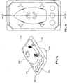
- FIG. 3a is a perspective drawing of the boat manoeuvring control unit according to an embodiment of the present invention.
- FIG. 3b is plan top view of the boat manoeuvring control unit of FIG. 2a, with a section line A-A in the vertical plane.
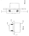
- FIG 4a is a rear view of the boat manoeuvring control unit of FIG. 2a.
- FIG 4b is a side view of the boat manoeuvring control unit of FIG. 2a, with a section line B-B in the horizontal plane.
- FIG. 5 shows the navicular control knob of the control unit according to an embodiment of the present invention, where:
- FIG. 5a is a rear view, showing a control knob vertical axis (z2).
- FIG. 5b is a side view, also showing said vertical axis (z2).
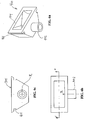
- FIG. 5c is a perspective drawing from below, showing alignment and locking features inside the control knob.
- FIG. 5d is a plan bottom view, also showing alignment and locking features.
- FIG. 6 shows the guide element according to an embodiment of the present invention, where:
- FIG. 6a is a perspective drawing from below.
- FIG. 6b is a front view, showing a guide element vertical axis (z1) and with a section line C-C in the horizontal plane.
- FIG. 6c is a plan top view, also showing said vertical axis (z1).
- FIG. 7 is a plan view along section C-C, as identified in FIG. 6b, showing a guide element cavity radius (k) and tangential angle (θ).
- FIG. 8 is an exploded view of the control unit according to an embodiment of the present invention.
- FIG. 9 is a cross sectional view along the section line A-A, as identified in FIG. 2b.
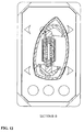
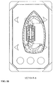
- FIGS. 10 through 17 are a plan section views along the section line B-B, as identified in FIG. 4b, where the control unit is shown in the following positions, inducing the following respective boat motions:
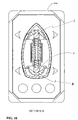
- FIG. 10: neutral; no motion.
- FIG. 11: forward part towards left hand side; bow motion towards port side.
- FIG. 12: forward part towards right hand side; bow motion towards starboard side.
- FIG. 13: aft part towards left hand side; stern motion towards port.
- FIG. 14: aft part towards right hand side; stern motion towards starboard.
- FIG. 15: forward part towards left hand side and aft part towards right hand side; bow motion towards port and stern motion towards starboard.
- FIG: 16: forward part towards right and aft part towards left; bow motion towards starboard and stern motion towards port.
- FIG. 17: sideways towards left; simultaneous bow and stern motion towards port.
- FIG. 18: sideways towards right; simultaneous bow and stern motion towards starboard.
- Referring to the FIGS. 1 - 18, the preferred embodiment of the control unit of the present invention comprises:
- a
base plate 100 with asocket 101, alower housing 110, and a number of attachment screws 102 andfairings 103; - a
switch panel 200 mounted on said base plate, where the switch panel has anopening 201 through which the plug extends, a number of on/off switches 202 (optional), and a number of embedded boat manoeuvring control switches 210; and - a boat shaped, or navicular,
control knob 500 mounted on the base plate such that it is displaceable over the switch panel. - The control knob is equipped with a number of pairs of forward- and
aft tongues knobs 505, and a number of corrugated orserrated fields 520 for providing a secure grip of the knob. - The control knob is generally mounted on the base plate by means of a
plug 300 and a pair of forward and aft guideelements 400. Theplug 300 has alongitudinal bore 301 for slidably receiving a guide pin 312 (optional) and acoil spring 310. The optional guide pin is coaxially located within the (coil) spring. The lower structure of the plug extends through the opening or aperture in the switch panel and is mounted in the socket. The pair of forward and aft guideelements 400 are mounted on the outer ends 311a of forward and aft plug pins 311. - The navicular control knob is mounted onto the pair of guide elements by means of the forward and aft snap locks engaging into respective ones of the forward and aft guide elements.
- The knob is aligned and supported on the guide elements by means of the forward and aft tongues being received into respective pairs of
grooves 401 on the forward and aft guide elements. The knob is horizontally aligned with the switch panel by means of a number of stabilising knobs symmetrically disposed along the control knob lower edge, and proximal with the upper surface of the panel. - The control knob- and guide element assembly is movably attached to the plug by means of forward and aft plug pins 311 being longitudinally aligned with the plug. The plug pins have outer ends 311a each being movably received into respective ones of forward and aft guide element cavities 403, and the plug pins have inner bores 311b for receiving opposite ends of the coil spring and guide pin assembly, the plug pins, guide pin and spring being slidably disposed in the plug longitudinal bore.
- Each guide element comprises a
lower housing 402 coaxial with vertical axis z1, for slidably receiving a one of anactuator spring 420 and a one of anactuator peg 425, each said spring being interposed between each said lower housing inner face and each said peg upper end, and where each said actuator peg is in slidable contact with said switch panel. - The actuator springs exert respective downward acting forces on said respective actuator peg, and the downward acting force is transmitted to the switch panel.
- In a non-actuated state, the navicular control knob remains in a neutral position in which position no one of said control switches are operated.
- By transmitting said downward acting force, the forward and aft actuator pegs activate the forward and aft embedded boat manoeuvring control switches respectively in a manner corresponding with a selective displacement of said navicular control knob.
- Any part of the navicular control knob is selectively rotably displaceable about a control knob vertical axis (z2), by selective application of a laterally directed force. Any part of the knob is selectively laterally displaceable by selective application of a laterally directed force.
- Due to the guide element having said cavity with a cavity radius (k), said plug having a plug end radius (r), and said plug spring having a spring constant (κ), the navicular control knob automatically returns to a said neutral position when said control knob is released. The cavity radius (k) is generally equal to a plug pin radius (t).
- It is advantageous to have employ one plug spring extending through the plug bore, instead of two individual spring associated with each plug pin. One plug spring facilitates an easier transverse movement and contributes in a favourable manner to keeping one knob end stationary, when the other is being moved. Such movement of a first control knob end will compress the plug spring axially and thus increase the pressure of the plug pin at the second end, which in turn applies a pressure towards its associated guide element; contributing to keeping the second end in a stationary position.
- The stabilising knobs symmetrically disposed along the control knob lower edge are proximal with the upper surface of said panel but do not come into contact with the boat manoeuvring control switches. The stabilising knobs prevent said control knob lower edge from engaging said switch panel and said embedded boat manoeuvring control switches.
- The plug guides said plug pins in axially opposing longitudinal directions. The plug outer ends have respective radii (r) corresponding to one half the minimum distance between said guide element rear
vertical surfaces 404. The navicular control knob is selectively rotable about a vertical axis (z2). The control knob is selectively rotable about a one of a pair of guide element vertical axes (z1). The knob is selectively laterally displaceable. - Each one of the embedded boat manoeuvring control switches is selectively individually slidably actuated by means of a respective one of said actuator peg. Each one of the embedded boat manoeuvring control switches is selectively individually actuated by means of selective manipulation of said navicular control knob. The navicular control knob longitudinal displacement when said control knob is rotated an angle (β), is limited by said radii (r) and said plug longitudinal dimension. The navicular control knob is axially fixed in a longitudinal direction when said control knob is in a non-actuated position. The navicular control knob is axially fixed in a longitudinal direction when said control knob is selectively laterally displaced.
- Each one of said downward acting forces on said respective actuator peg is sufficient to retain a one of said actuator peg in a said neutral position when said other of said actuator peg is selectively laterally displaced.
- In an alternative embodiment, the forward and aft guide elements are integral with the control knob.
- In one alternative embodiment, the number of actuator pegs corresponds to the number of boat manoeuvring control switches.
- In yet another embodiment of the invention, the panel boat manoeuvring control switches may comprise any number of switches.
- In yet another embodiment of the present invention, the boat manoeuvring control switch means are a plurality of micro switches mounted on said panel.
- In yet another embodiment of the present invention , the boat manoeuvring control switches are micro switches disposed inside each one of said guide element cavity, for actuation by said plug pins.
- The control unit may also control the forward and aft motion of a
boat 10. The control unit may also be a main propulsion control unit of said boat, if additional switches controlling the main propulsion systems, are added - internally or externally - to the control knob. - Bow and
stern thrusters 11, 12 on aboat 10 may be controlled by means of the boat manoeuvring control unit in accordance with the invention, where the method comprises a selection of one or more of the following steps: - displacing said navicular control knob forward part in a left hand direction to accomplish a bow thruster force inducing a port hand bow motion;
- displacing said navicular control knob forward part in a right hand direction to accomplish a bow thruster force inducing a starboard hand bow motion;
- displacing said navicular control knob aft part in a left hand direction to accomplish a stern thruster force inducing a port hand stern motion;
- displacing said navicular control knob aft part in a right hand direction to accomplish a stem thruster force inducing a starboard hand stern motion;
- displacing said navicular control knob forward part in a left hand direction and said navicular control knob aft part in a right hand direction to simultaneously accomplish respectively a bow thruster force inducing a port hand bow motion and a stern thruster force inducing a starboard hand stern motion;
- displacing said navicular control knob forward part in a right hand direction and said navicular control knob aft part in a left hand direction to simultaneously accomplish respectively a bow thruster force inducing a starboard hand bow motion and a stern thruster force inducing a port hand stern motion;
- laterally displacing said navicular control knob in a left hand direction to simultaneously accomplish a bow thruster force and a stern thruster force inducing a generally lateral port hand motion;
- laterally displacing said navicular control knob in a right hand direction to simultaneously accomplish a bow thruster force and a stern thruster force inducing a generally lateral starboard hand motion.
- Thus, the boat manoeuvring control unit in accordance with the invention may be used to control thrusters on a boat. Indeed, any boat propulsion unit may be controlled by the control unit according to the invention, e.g. any number of bow and stern thrusters, main and/or auxiliary propulsion units.
- The invented control unit allows for a method for controlling a boat, employing not only conventional thrusters, but any number of a plurality of any other boat propulsion unit.
- The boat manoeuvring control unit in accordance with accordance with the invention may be used for controlling any plurality of propulsion units on a boat. The boat manoeuvring control unit in accordance with accordance with the invention may be used for controlling the main of propulsion units on a boat.
- The foregoing description and the embodiments of the present invention are to be construed as mere illustrations of the application of the principles of the invention. The foregoing is not intended to limit the scope of the claims, but the scope of present invention is defined by the claims.
Claims (46)
- A boat manoeuvring control unit, comprising:- a base plate (100) having a socket (101), a lower housing (110), and attachment means (102, 103);- a switch panel (200) mounted on said base plate, said switch panel having a plug receiving aperture (201), and a number of boat manoeuvring control switch means (210); and- a navicular control knob (500) mounted on said base plate (100),characterized in that the control knob (500) is displaceable over said panel, said control knob (500) having a plurality of engagement means (501, 502, 503, 504), said control knob (500) having the general shape of a boat hull and being mounted on said base plate (100) by means of:- a plug (300) having a longitudinal bore (301) for slidably receiving a coil spring (310), said plug lower structure extending through said aperture (201) and being mounted in said socket (101); and- a pair of forward and aft guide elements (400) mounted on the outer ends of forward and aft plug pins (311) and engaging said engaging means (501, 502, 503, 504), respectively.
- The boat manoeuvring control unit in accordance with claim 1, wherein said control knob (500) further being mounted onto said pair of guide elements (400) by means of said engagement means (501, 502, 503, 504) engaging into respective said forward and aft guide elements (400) and aligned and supported on said guide elements by means of said engagement means being received on said forward and aft guide elements.
- The boat manoeuvring control unit in accordance with claims 1 and 2, wherein said control knob and guide element assembly (500-504) is movably attached to said plug (300) by means of forward and aft plug pins (311) being longitudinally aligned with said plug (300) and where said plug pins (311) having outer ends each being movably received into respective ones of forward and aft guide element cavities (403), said plug pins (311) having inner bores for receiving opposite ends of said coil spring (310), said plug pins and spring being slidably disposed in said plug longitudinal bore (301).
- The boat manoeuvring control unit in accordance with claims 1-3, wherein each of said guide elements (400) comprises a lower housing (402) coaxial with a vertical axis (Z1), for slidably receiving an actuator spring (420) and an actuator peg (425), said actuator spring (420) being interposed between the lower housing inner face and the peg upper end, and where said actuator peg (425) is proximal with the switch panel (200).
- The boat manoeuvring control unit in accordance with claim 4, wherein said actuator springs (420) exert respective downward acting forces on said respective actuator peg (425), and wherein said downward acting force is selectively transmitted to said switch (210).
- The boat manoeuvring control unit in accordance with claim 1, wherein said navicular control knob (500) in a non-actuated state remains in a neutral position in which position no one of said control switches (210) are operated.
- The boat manoeuvring control unit in accordance with claim 4, wherein the forward and aft actuator pegs (425) by transmitting said downward acting force, activate the forward and aft boat manoeuvring control switches (210), respectively, in a manner corresponding with a selective displacement of said navicular control knob (500).
- The boat manoeuvring control unit in accordance with claim 1, wherein any part of said navicular control knob (500) is selectively rotatably displaceable about a control knob vertical axis (Z2) by selective application of a laterally directed force.
- The boat manoeuvring control unit in accordance with claim 1, wherein any part of said navicular control knob (500) is selectively laterally displaceable by selective application of a laterally directed force.
- The boat manoeuvring control unit in accordance with claim 1, wherein said attachment means each comprise a number of attachment screws (102) and fairings (103).
- The boat manoeuvring control unit in accordance with claim 1, wherein said switch panel (200) is a diaphragm touch switch panel.
- The boat manoeuvring control unit in accordance with claim 1, wherein said boat manoeuvring control switch means (210) are a plurality of embedded boat manoeuvring control switches.
- The boat manoeuvring control unit in accordance with claim 1, wherein said boat manoeuvring control switch means (210) are a plurality of micro switches mounted on said panel.
- The boat manoeuvring control unit in accordance with any of the preceding claims, said engagement means comprising a plurality of pairs of forward and aft tongues (501, 502), and forward and aft snap locks (503, 504).
- The boat manoeuvring control unit in accordance with any of the preceding claims, wherein said navicular control knob (500) comprises horizontal alignment features (505).
- The boat manoeuvring control unit in accordance with claim 15, wherein said horizontal alignment features comprise a plurality of stabilising knobs (505) symmetrically disposed along said control knob lower edge to be proximal with the upper surface of said panel (200).
- The boat manoeuvring control unit in accordance with any of the preceding claims, wherein said navicular control knob (500) comprises a number of serrated or corrugated fields (520).
- The boat manoeuvring control unit in accordance with any of the preceding claims, wherein said navicular control knob (500) by means of said guide element (400) having said cavity with a cavity radius (k), said plug pins (311) having a plug pin end radius (r), and said plug spring (310) having a spring constant, automatically returns to a said neutral position when said control knob (500) is released.
- The boat manoeuvring control unit in accordance with claim 18, wherein said cavity radius (k) is generally equal to a plug pin radius (r).
- The boat manoeuvring control unit in accordance with claim 16, wherein said stabilising knobs (505) symmetrically disposed along said control knob lower edge are proximal with the upper surface of said panel (200) but not with said embedded boat manoeuvring control switches (210).
- The boat manoeuvring control unit in accordance with claim 20, wherein said stabilising knobs (505) prevent said control knob lower edge from engaging said switch panel (200) and said embedded boat manoeuvring control switches (210).
- The boat manoeuvring control unit in accordance with any of the preceding claims, wherein said plug (300) guides said plug pins (311) in axially opposing longitudinal directions.
- The boat manoeuvring control unit in accordance with any of claims 3-22, wherein said plug pin outer ends have respective radii (r) corresponding to one half of the minimum distance between said guide element rear vertical surfaces.
- The boat manoeuvring control unit in accordance with any of the preceding claims, wherein said navicular control knob (500) is selectively rotatable about a vertical axis (Z2).
- The boat manoeuvring control unit in accordance with any of the preceding claims, wherein said navicular control knob (500) is selectively rotatable about a respective of a pair of guide element vertical axes (Z1).
- The boat manoeuvring control unit in accordance with any of the preceding claims, wherein said navicular control knob (500) is selectively laterally displaceable.
- The boat manoeuvring control unit in accordance with claim 4, wherein each one of said embedded boat manoeuvring control switches (210) is selectively individually slidably actuated by means of a respective one of said actuator pegs (425).
- The boat manoeuvring control unit in accordance with any of the preceding claims, wherein each one of said embedded boat manoeuvring control switches (210) is selectively individually actuated by means of selective manipulation of said navicular control knob (500).
- The boat manoeuvring control unit in accordance with claim (23), wherein said navicular control knob longitudinal displacement when said control knob (500) is rotated an angle, is limited by said radii (r) and said plug longitudinal dimension.
- The boat manoeuvring control unit in accordance with any of the preceding claims, wherein said navicular control knob (500) is axially fixed in a longitudinal direction when said control knob is in a non-actuated position.
- The boat manoeuvring control unit in accordance with any of the preceding claims, wherein said navicular control knob (500) is axially fixed in a longitudinal direction when said control knob is selectively laterally displaced.
- The boat manoeuvring control unit in accordance with claim 5, wherein each one of the downward acting forces on said respective actuator peg (425) is sufficient to retain one of the actuator pegs in a neutral position when said other of said actuator pegs is selectively laterally displaced.
- The boat manoeuvring control unit in accordance with any of the preceding claims, wherein said control unit controls the forward and aft motion of a boat.
- The boat manoeuvring control unit in accordance with any of the preceding claims, wherein said control unit is a main propulsion control unit of said boat.
- The boat manoeuvring control unit in accordance with claim 1, wherein said coil spring (310) is longitudinally guided by a guide pin (312), said pin being coaxially located within said spring, and said plug longitudinal bore (301) slidably receiving said guide pin (312) and spring (310).
- The boat manoeuvring control unit in accordance with any of the preceding claims, wherein said control unit employs one coil spring (310).
- The boat manoeuvring control unit in accordance with any of the preceding claims, wherein said forward and aft guide elements are integral with said control knob.
- The boat manoeuvring control unit in accordance with any of the preceding claims, wherein said switch panel (200) comprise a plurality of on/off switches (202).
- The boat manoeuvring control unit in accordance with any of claims 3-38, wherein said boat manoeuvring control switches are micro switches disposed inside each one of said guide element cavities, for actuation by said plug pins (311).
- The boat manoeuvring control unit in accordance with claim 4 wherein said actuator pegs (425) in number correspond to the number of boat manoeuvring control switches (210).
- The boat manoeuvring control unit in accordance with any of the preceding claims, wherein said panel boat manoeuvring control switches (210) are any number of switches.
- A method for controlling bow and stem thrusters on a boat by means of a boat manoeuvring control unit in accordance with any of the preceding claims, the method comprising a selection of one or more of the following steps:- displacing said navicular control knob (500) forward part in a left hand direction to accomplish a bow thruster force inducing a port hand bow motion;- displacing said navicular control knob forward part in a right hand direction to accomplish a bow thruster force inducing a starboard hand bow motion;- displacing said navicular control knob aft part in a left hand to accomplish a stern thruster force inducing a port hand stem motion;- displacing said navicular control knob aft part in a right hand direction to accomplish a stem thruster force inducing a starboard hand stern motion;- displacing said navicular control knob forward part in a left hand direction and said navicular control knob aft part in a right hand direction to simultaneously accomplish respectively a bow thruster force inducing a port hand bow motion and a stem thruster force inducing a starboard hand stem motion;- displacing said navicular control knob forward part in a right hand direction and said navicular control knob aft part in a left hand direction to simultaneously accomplish respectively a bow thruster force inducing a starboard hand bow motion and a stem thruster force inducing a port hand stem motion;- laterally displacing said navicular control knob in a left hand direction to simultaneously accomplish a bow thruster force and a stern thruster force inducing a generally lateral port hand motion;- laterally displacing said navicular control knob in a right hand direction to simultaneously accomplish a bow thruster force and a stem thruster force inducing a generally lateral starboard hand motion.
- The method in accordance with claim 42, wherein said bow thruster force and stem thruster force individually and/or separately may be any number of a plurality of forces generated by any one of a plurality of any other boat propulsion unit.
- Use of a boat manoeuvring control unit in accordance with any of claims 1-41 for controlling thrusters (11, 12) on a boat (15).
- Use of a boat manoeuvring control unit in accordance with any of claims 1-41 for controlling any plurality of propulsion units on a boat.
- Use of a boat manoeuvring control unit in accordance with any of claims 1-41 for controlling the main of propulsion units on a boat.
Applications Claiming Priority (2)
| Application Number | Priority Date | Filing Date | Title |
|---|---|---|---|
| US09/679,803 US6538217B1 (en) | 2000-10-05 | 2000-10-05 | Manually operable suitable control unit for a boat |
| US679803 | 2000-10-05 |
Publications (3)
| Publication Number | Publication Date |
|---|---|
| EP1195320A2 EP1195320A2 (en) | 2002-04-10 |
| EP1195320A3 EP1195320A3 (en) | 2003-01-15 |
| EP1195320B1 true EP1195320B1 (en) | 2006-11-29 |
Family
ID=24728433
Family Applications (1)
| Application Number | Title | Priority Date | Filing Date |
|---|---|---|---|
| EP01203750A Expired - Lifetime EP1195320B1 (en) | 2000-10-05 | 2001-10-04 | Boat control unit |
Country Status (5)
| Country | Link |
|---|---|
| US (1) | US6538217B1 (en) |
| EP (1) | EP1195320B1 (en) |
| AT (1) | ATE346788T1 (en) |
| DE (1) | DE60124838D1 (en) |
| NO (1) | NO325001B1 (en) |
Cited By (2)
| Publication number | Priority date | Publication date | Assignee | Title |
|---|---|---|---|---|
| WO2014038953A1 (en) | 2012-09-06 | 2014-03-13 | Sleipner Motor As | Joystick, system and method for manoeuvring a boat |
| EP4714819A1 (en) | 2024-09-18 | 2026-03-25 | Ultraflex S.P.A. | Method and system for governing a vessel or the like provided with a single engine |
Families Citing this family (13)
| Publication number | Priority date | Publication date | Assignee | Title |
|---|---|---|---|---|
| US6957990B2 (en) * | 2002-08-21 | 2005-10-25 | Lowe Jerry W | Electric houseboat |
| US7121220B2 (en) * | 2003-04-04 | 2006-10-17 | Ie-Tec Licensing Limited | Steering mechanism for watercraft |
| WO2006062416A1 (en) * | 2004-12-07 | 2006-06-15 | Cwf Hamilton & Co Limited | Propulsion and control system for a marine vessel |
| WO2007055605A1 (en) * | 2005-11-12 | 2007-05-18 | Cwf Hamilton & Co Limited | Propulsion and control system for a marine vessel |
| WO2007055606A1 (en) * | 2005-11-12 | 2007-05-18 | Cwf Hamilton & Co Limited | Propulsion and control system for a marine vessel |
| US8126602B2 (en) * | 2006-12-19 | 2012-02-28 | Morvillo Robert A | Method and apparatus for controlling a water-jet driven marine vessel |
| ITRM20080124A1 (en) * | 2008-03-06 | 2009-09-07 | Stefano Bertazzoni | MANUAL CONTROL DEVICE TO CHECK THE MOVEMENT OF REAL OR VIRTUAL ITEMS |
| WO2010039952A1 (en) * | 2008-10-02 | 2010-04-08 | Zf Friedrichshafen Ag | Joystick controlled marine maneuvering system |
| JP5243978B2 (en) * | 2009-01-27 | 2013-07-24 | ヤマハ発動機株式会社 | Marine propulsion system and ship maneuvering method |
| US20120295501A1 (en) | 2010-11-05 | 2012-11-22 | Kennon Guglielmo | Apparatus and Method for the Control of Engine Throttle for Inboard and Outboard Boat Motors |
| US8888544B1 (en) | 2011-12-01 | 2014-11-18 | Enovation Controls, Llc | Versatile control handle for watercraft docking system |
| USD742418S1 (en) * | 2012-11-13 | 2015-11-03 | Wartsila Finland Oy | Propulsion control system for ship with a display |
| US11208181B1 (en) | 2019-04-30 | 2021-12-28 | Christopher J. Beall | Bow fishing illumination system |
Family Cites Families (11)
| Publication number | Priority date | Publication date | Assignee | Title |
|---|---|---|---|---|
| US3919510A (en) * | 1973-05-29 | 1975-11-11 | Brunswick Corp | Electrically controlled shift mechanism for marine propulsion units |
| US4180713A (en) * | 1975-06-25 | 1979-12-25 | Societe Anonyme Automobiles Citroen | Switch control unit for automobile vehicle |
| JPS6120000Y2 (en) * | 1978-12-06 | 1986-06-16 | ||
| FR2580240B1 (en) * | 1985-04-10 | 1987-07-10 | Citroen Maxime | GROUPING DEVICE CONSTITUTING A KEYBOARD OF CONTACTORS FOR CONTROLLING EQUIPMENT INSTALLED IN A MOTOR VEHICLE |
| US5446253A (en) * | 1994-04-21 | 1995-08-29 | Eaton Corporation | Switch actuator assembly |
| NO303112B1 (en) * | 1996-01-23 | 1998-06-02 | Kvaerner Asa | Steering and maneuvering connectors for a vessel |
| US5680927A (en) * | 1996-09-30 | 1997-10-28 | United Technologies Automotive, Inc. | Electrical switch |
| NO965218L (en) * | 1996-12-06 | 1998-06-08 | Kvaerner Asa | Steering and maneuvering plugs |
| US6142841A (en) | 1998-05-14 | 2000-11-07 | Brunswick Corporation | Waterjet docking control system for a marine vessel |
| US6280269B1 (en) * | 2000-03-01 | 2001-08-28 | Brunswick Corporation | Operator display panel control by throttle mechanism switch manipulation |
| US6273771B1 (en) * | 2000-03-17 | 2001-08-14 | Brunswick Corporation | Control system for a marine vessel |
-
2000
- 2000-10-05 US US09/679,803 patent/US6538217B1/en not_active Expired - Fee Related
-
2001
- 2001-09-28 NO NO20014732A patent/NO325001B1/en not_active IP Right Cessation
- 2001-10-04 AT AT01203750T patent/ATE346788T1/en not_active IP Right Cessation
- 2001-10-04 EP EP01203750A patent/EP1195320B1/en not_active Expired - Lifetime
- 2001-10-04 DE DE60124838T patent/DE60124838D1/en not_active Expired - Lifetime
Cited By (3)
| Publication number | Priority date | Publication date | Assignee | Title |
|---|---|---|---|---|
| WO2014038953A1 (en) | 2012-09-06 | 2014-03-13 | Sleipner Motor As | Joystick, system and method for manoeuvring a boat |
| US9387916B2 (en) | 2012-09-06 | 2016-07-12 | Sleipner Motor As | Joystick, system and method for manouvering a boat |
| EP4714819A1 (en) | 2024-09-18 | 2026-03-25 | Ultraflex S.P.A. | Method and system for governing a vessel or the like provided with a single engine |
Also Published As
| Publication number | Publication date |
|---|---|
| ATE346788T1 (en) | 2006-12-15 |
| EP1195320A3 (en) | 2003-01-15 |
| NO20014732L (en) | 2002-04-08 |
| US6538217B1 (en) | 2003-03-25 |
| EP1195320A2 (en) | 2002-04-10 |
| NO325001B1 (en) | 2008-01-14 |
| NO20014732D0 (en) | 2001-09-28 |
| DE60124838D1 (en) | 2007-01-11 |
Similar Documents
| Publication | Publication Date | Title |
|---|---|---|
| US6538217B1 (en) | Manually operable suitable control unit for a boat | |
| US6511354B1 (en) | Multipurpose control mechanism for a marine vessel | |
| US7467595B1 (en) | Joystick method for maneuvering a marine vessel with two or more sterndrive units | |
| US6357375B1 (en) | Boat thruster control apparatus | |
| US8387551B2 (en) | Double trim tab | |
| US9387916B2 (en) | Joystick, system and method for manouvering a boat | |
| JP2824072B2 (en) | Steering and steering system for water transport vessels | |
| US6234853B1 (en) | Simplified docking method and apparatus for a multiple engine marine vessel | |
| US3587512A (en) | Boat with secondary propulsion means | |
| AU2005312429A1 (en) | Propulsion and control system for a marine vessel | |
| JP2002137795A (en) | Remote control device for small ship | |
| US20180201354A1 (en) | Wireless controller | |
| US3848561A (en) | Boat | |
| US20120285355A1 (en) | Multi-function auxiliary rudder system for jet propelled watercrafts | |
| CN114126960A (en) | Water skis | |
| JP2000054705A (en) | Cover locking device | |
| US20110247539A1 (en) | Personal watercraft | |
| JPH0585471A (en) | Small-sized hydrovehicle | |
| US5425321A (en) | Sailboard and the like | |
| US12222718B2 (en) | Marine vessel maneuvering system, and marine vessel | |
| US7044815B1 (en) | Remotely steerable mount for boat propulsion motor | |
| JP3715710B2 (en) | Jet propulsion nozzle drive system for small vessels | |
| JPH07478B2 (en) | Left-right reversible operation lever | |
| JP4005493B2 (en) | Trim control device for small surface boat | |
| KR200262578Y1 (en) | tortoise-shaped ship |
Legal Events
| Date | Code | Title | Description |
|---|---|---|---|
| PUAI | Public reference made under article 153(3) epc to a published international application that has entered the european phase |
Free format text: ORIGINAL CODE: 0009012 |
|
| AK | Designated contracting states |
Kind code of ref document: A2 Designated state(s): AT BE CH CY DE DK ES FI FR GB GR IE IT LI LU MC NL PT SE TR |
|
| AX | Request for extension of the european patent |
Free format text: AL;LT;LV;MK;RO;SI |
|
| PUAL | Search report despatched |
Free format text: ORIGINAL CODE: 0009013 |
|
| AK | Designated contracting states |
Kind code of ref document: A3 Designated state(s): AT BE CH CY DE DK ES FI FR GB GR IE IT LI LU MC NL PT SE TR |
|
| AX | Request for extension of the european patent |
Free format text: AL;LT;LV;MK;RO;SI |
|
| RIC1 | Information provided on ipc code assigned before grant |
Free format text: 7B 63H 21/22 A, 7B 63H 25/02 B, 7B 63H 25/42 B, 7G 05G 9/047 B |
|
| 17P | Request for examination filed |
Effective date: 20030508 |
|
| AKX | Designation fees paid |
Designated state(s): AT BE CH CY DE DK ES FI FR GB GR IE IT LI LU MC NL PT SE TR |
|
| 17Q | First examination report despatched |
Effective date: 20030901 |
|
| GRAP | Despatch of communication of intention to grant a patent |
Free format text: ORIGINAL CODE: EPIDOSNIGR1 |
|
| GRAS | Grant fee paid |
Free format text: ORIGINAL CODE: EPIDOSNIGR3 |
|
| GRAA | (expected) grant |
Free format text: ORIGINAL CODE: 0009210 |
|
| AK | Designated contracting states |
Kind code of ref document: B1 Designated state(s): AT BE CH CY DE DK ES FI FR GB GR IE IT LI LU MC NL PT SE TR |
|
| PG25 | Lapsed in a contracting state [announced via postgrant information from national office to epo] |
Ref country code: LI Free format text: LAPSE BECAUSE OF FAILURE TO SUBMIT A TRANSLATION OF THE DESCRIPTION OR TO PAY THE FEE WITHIN THE PRESCRIBED TIME-LIMIT Effective date: 20061129 Ref country code: FI Free format text: LAPSE BECAUSE OF FAILURE TO SUBMIT A TRANSLATION OF THE DESCRIPTION OR TO PAY THE FEE WITHIN THE PRESCRIBED TIME-LIMIT Effective date: 20061129 Ref country code: CH Free format text: LAPSE BECAUSE OF FAILURE TO SUBMIT A TRANSLATION OF THE DESCRIPTION OR TO PAY THE FEE WITHIN THE PRESCRIBED TIME-LIMIT Effective date: 20061129 Ref country code: BE Free format text: LAPSE BECAUSE OF FAILURE TO SUBMIT A TRANSLATION OF THE DESCRIPTION OR TO PAY THE FEE WITHIN THE PRESCRIBED TIME-LIMIT Effective date: 20061129 Ref country code: AT Free format text: LAPSE BECAUSE OF FAILURE TO SUBMIT A TRANSLATION OF THE DESCRIPTION OR TO PAY THE FEE WITHIN THE PRESCRIBED TIME-LIMIT Effective date: 20061129 |
|
| REG | Reference to a national code |
Ref country code: GB Ref legal event code: FG4D |
|
| REG | Reference to a national code |
Ref country code: IE Ref legal event code: FG4D Ref country code: CH Ref legal event code: EP |
|
| REG | Reference to a national code |
Ref country code: IE Ref legal event code: FG4D |
|
| REF | Corresponds to: |
Ref document number: 60124838 Country of ref document: DE Date of ref document: 20070111 Kind code of ref document: P |
|
| PG25 | Lapsed in a contracting state [announced via postgrant information from national office to epo] |
Ref country code: SE Free format text: LAPSE BECAUSE OF FAILURE TO SUBMIT A TRANSLATION OF THE DESCRIPTION OR TO PAY THE FEE WITHIN THE PRESCRIBED TIME-LIMIT Effective date: 20070228 Ref country code: DK Free format text: LAPSE BECAUSE OF FAILURE TO SUBMIT A TRANSLATION OF THE DESCRIPTION OR TO PAY THE FEE WITHIN THE PRESCRIBED TIME-LIMIT Effective date: 20070228 |
|
| PG25 | Lapsed in a contracting state [announced via postgrant information from national office to epo] |
Ref country code: DE Free format text: LAPSE BECAUSE OF FAILURE TO SUBMIT A TRANSLATION OF THE DESCRIPTION OR TO PAY THE FEE WITHIN THE PRESCRIBED TIME-LIMIT Effective date: 20070301 |
|
| PG25 | Lapsed in a contracting state [announced via postgrant information from national office to epo] |
Ref country code: ES Free format text: LAPSE BECAUSE OF FAILURE TO SUBMIT A TRANSLATION OF THE DESCRIPTION OR TO PAY THE FEE WITHIN THE PRESCRIBED TIME-LIMIT Effective date: 20070312 |
|
| PG25 | Lapsed in a contracting state [announced via postgrant information from national office to epo] |
Ref country code: PT Free format text: LAPSE BECAUSE OF FAILURE TO SUBMIT A TRANSLATION OF THE DESCRIPTION OR TO PAY THE FEE WITHIN THE PRESCRIBED TIME-LIMIT Effective date: 20070430 |
|
| REG | Reference to a national code |
Ref country code: CH Ref legal event code: PL |
|
| ET | Fr: translation filed | ||
| PLBE | No opposition filed within time limit |
Free format text: ORIGINAL CODE: 0009261 |
|
| STAA | Information on the status of an ep patent application or granted ep patent |
Free format text: STATUS: NO OPPOSITION FILED WITHIN TIME LIMIT |
|
| 26N | No opposition filed |
Effective date: 20070830 |
|
| PGFP | Annual fee paid to national office [announced via postgrant information from national office to epo] |
Ref country code: NL Payment date: 20071029 Year of fee payment: 7 |
|
| PGFP | Annual fee paid to national office [announced via postgrant information from national office to epo] |
Ref country code: IT Payment date: 20071029 Year of fee payment: 7 |
|
| PG25 | Lapsed in a contracting state [announced via postgrant information from national office to epo] |
Ref country code: GR Free format text: LAPSE BECAUSE OF FAILURE TO SUBMIT A TRANSLATION OF THE DESCRIPTION OR TO PAY THE FEE WITHIN THE PRESCRIBED TIME-LIMIT Effective date: 20070301 |
|
| PGFP | Annual fee paid to national office [announced via postgrant information from national office to epo] |
Ref country code: GB Payment date: 20071031 Year of fee payment: 7 Ref country code: FR Payment date: 20071031 Year of fee payment: 7 |
|
| PG25 | Lapsed in a contracting state [announced via postgrant information from national office to epo] |
Ref country code: MC Free format text: LAPSE BECAUSE OF NON-PAYMENT OF DUE FEES Effective date: 20071031 |
|
| PG25 | Lapsed in a contracting state [announced via postgrant information from national office to epo] |
Ref country code: IE Free format text: LAPSE BECAUSE OF NON-PAYMENT OF DUE FEES Effective date: 20071004 |
|
| GBPC | Gb: european patent ceased through non-payment of renewal fee |
Effective date: 20081004 |
|
| NLV4 | Nl: lapsed or anulled due to non-payment of the annual fee |
Effective date: 20090501 |
|
| REG | Reference to a national code |
Ref country code: FR Ref legal event code: ST Effective date: 20090630 |
|
| PG25 | Lapsed in a contracting state [announced via postgrant information from national office to epo] |
Ref country code: NL Free format text: LAPSE BECAUSE OF NON-PAYMENT OF DUE FEES Effective date: 20090501 |
|
| PG25 | Lapsed in a contracting state [announced via postgrant information from national office to epo] |
Ref country code: LU Free format text: LAPSE BECAUSE OF NON-PAYMENT OF DUE FEES Effective date: 20071004 Ref country code: IT Free format text: LAPSE BECAUSE OF NON-PAYMENT OF DUE FEES Effective date: 20081004 Ref country code: CY Free format text: LAPSE BECAUSE OF FAILURE TO SUBMIT A TRANSLATION OF THE DESCRIPTION OR TO PAY THE FEE WITHIN THE PRESCRIBED TIME-LIMIT Effective date: 20061129 |
|
| PG25 | Lapsed in a contracting state [announced via postgrant information from national office to epo] |
Ref country code: TR Free format text: LAPSE BECAUSE OF FAILURE TO SUBMIT A TRANSLATION OF THE DESCRIPTION OR TO PAY THE FEE WITHIN THE PRESCRIBED TIME-LIMIT Effective date: 20061129 |
|
| PG25 | Lapsed in a contracting state [announced via postgrant information from national office to epo] |
Ref country code: FR Free format text: LAPSE BECAUSE OF NON-PAYMENT OF DUE FEES Effective date: 20081031 |
|
| PG25 | Lapsed in a contracting state [announced via postgrant information from national office to epo] |
Ref country code: GB Free format text: LAPSE BECAUSE OF NON-PAYMENT OF DUE FEES Effective date: 20081004 |