EP1195227A2 - Method and apparatus for edge grinding of vertically stacked plate items - Google Patents
Method and apparatus for edge grinding of vertically stacked plate items Download PDFInfo
- Publication number
- EP1195227A2 EP1195227A2 EP01123493A EP01123493A EP1195227A2 EP 1195227 A2 EP1195227 A2 EP 1195227A2 EP 01123493 A EP01123493 A EP 01123493A EP 01123493 A EP01123493 A EP 01123493A EP 1195227 A2 EP1195227 A2 EP 1195227A2
- Authority
- EP
- European Patent Office
- Prior art keywords
- grinding
- items
- stacks
- cylinders
- registering
- Prior art date
- Legal status (The legal status is an assumption and is not a legal conclusion. Google has not performed a legal analysis and makes no representation as to the accuracy of the status listed.)
- Withdrawn
Links
Images


Classifications
-
- B—PERFORMING OPERATIONS; TRANSPORTING
- B24—GRINDING; POLISHING
- B24B—MACHINES, DEVICES, OR PROCESSES FOR GRINDING OR POLISHING; DRESSING OR CONDITIONING OF ABRADING SURFACES; FEEDING OF GRINDING, POLISHING, OR LAPPING AGENTS
- B24B9/00—Machines or devices designed for grinding edges or bevels on work or for removing burrs; Accessories therefor
- B24B9/02—Machines or devices designed for grinding edges or bevels on work or for removing burrs; Accessories therefor characterised by a special design with respect to properties of materials specific to articles to be ground
- B24B9/18—Machines or devices designed for grinding edges or bevels on work or for removing burrs; Accessories therefor characterised by a special design with respect to properties of materials specific to articles to be ground of wood
Definitions
- the present invention concerns a method for edge grinding of plate items in a vertical stack, e.g. laminboards, where a grinding apparatus is used, comprising a number of vertical shafts for a number of abrasive rollers forming vertical grinding cylinders with a length adapted to the height of the stacks of items and which are driven by each their drive motor so that the grinding cylinders may be rotated in each their direction of rotation, which grinding cylinders are suspended in a turning ring by a trolley which is displaceable in the transverse direction relative to a support beam displaceable along a rollerpath for the stacks of items and a fixation device for the stacks of items arranged along the rollerpath, and where there is used a computerised, combined electronic and pneumatic control system.
- laminboards are used in the production of furniture like shelves and bookcases.
- the laminboards are varniched several times, and an intermediate grinding is to be performed as the surface of the laminboards "rises" by the first varnishing.
- the laminboards are placed in stacks which are advanced by rollerpaths between the respective varnishing and grinding stations where varnishing and edge grinding is performed manually. Even if protective equipment is used to some extent in connection with the manual varnishing work, e.g. facial mask with breathing protection, the working environment is bad.
- edge grinding itself which until now also has been performed by means of manual grinding equipment, also implies a serious work environmental strain, as the grinding equipment, even if it is suspended in a resilient carrying strap system and connected with a suction hose, is relatively heavy to operate because the pressing against as well as the lateral movement of the grinding equipment (grinding roller of abrasive strips and intermediate support brushes) along the stack of items occur manually.
- the fact that the grinding work occurs manually furthermore has negative influence on the quality of the grinding work which, in order to achieve a uniform quality, requires very precisely controlled grinding movements in addition to using a certain direction of rotation, namely so that the co-rotating grinding roller (having same direction of rotation and displacement), from being moved inward against the edges of the stack, is moved horizontally outward past the end edges of the plate items.
- EP-A2-1 034 882 which describes an apparatus for edge grinding plate items in a vertical stack, e.g. laminboards.
- the method according to the invention is characterised in that programming of the control computer occurs by means of a separate registering carriage which is arranged to perform the same pattern of movement as the grinding cylinders, and which has a registering wheel representing the respective grinding cylinders and preferably a further registering wheel representing a vertical row of air nozzles, where the registering wheel is moved manually along selected sections of the outer edges of the stacks of items so that the grinding cylinders subsequently are performing the same pattern of movement for performing the desired edge grinding and final blowing off of grinding dust, as suitable means for regulating pressure controlled pressing of the grinding cylinders against the outer edges of the stacks of items are used.
- the programming may be performed by the machine operator without any knowledge of programming computers by means of a registering carriage with two registering wheels, each positionally representating two grinding cylinders rotating in each their direction of rotation, and with a third registering wheel representing a vertical row of air nozzles which are situated in the middle between the grinding cylinders and serve to blow the outer edges of the items in the stack of items free from grinding dust.
- the respective registering wheels, each representing a grinding cylinder with a certain direction of rotation is moved with wheel contact along the external contour of the item stack as the exact pattern of movement is simultaneously registered by impulse counters so that positional co-ordinates of the registering wheel arrangement is registered concurrently.
- the direction of rotation of the grinding cylinders along sections of the stack of items may furthermore be controlled by means of a keyboard comprising a display which shows the current position co-ordinates for the registering wheel arrangement at any time.
- the invention also concerns an apparatus for edge grinding plate items in a vertical stack, e.g. laminboards, and comprising a number of vertical shafts for a number of abrasive rollers forming vertical grinding cylinders with a length adapted to the height of the stacks of items, and which are driven by each their drive motor so that the grinding cylinders may be rotated in each their direction of rotation, the grinding cylinders being suspended by a turning ring by a trolley which is displaceable in the transverse direction of a support beam displaceable along a rollerpath for the stacks of items and a fixation device for the stacks of items arranged along the rollerpath, and where there is used a computerised, combined electronic and pneumatic control system, where the apparatus is peculiar in comprising a separate registering carriage which is arranged to perform the same pattern of movement as the grinding cylinders, and which has a registering wheel representing the respective grinding cylinders and preferably a further registering wheel representing a vertical row of air nozzles, registering wheels being
- the apparatus according to the invention is suitably designed so that the said means for regulating pressure controlled pressing of the grinding cylinders are constituted by mechanical setting screws with measuring rulers for each of the registering wheels so that the actual location of the point of contact of the registering wheels with the side of the stack of items representing the effective periphery of the grinding cylinders may be preset in dependence on empirical parameters such as type of coating, degree of hardening of coating, rigidity of grinding cylinders, grinding capacity of grinding cylinders etc.
- the apparatus according to the invention may be arranged with particular advantage so that in connection with the registering wheel arrangement, the apparatus comprises a keyboard with display for providing control information such as current rotational speed and for showing current location co-ordinates.
- the separate registering carriage may comprise impulse counters for registering the current position and configuration of the current stack of items.
- the apparatus may advantageously be thus designed so that at both sides of the rollerpath on which the stack of items is placed during the grinding process, the apparatus comprises holding cylinders that each are arranged to interact with elevating clamping members situated between the rollers of the rollerpath for lifting free the stack of items while this is held by the holding cylinder located at the side of the stack which faces away from the side ground, i.e. the holding cylinder at the opposite side is automatically deactivated when the grinding cylinder is finished with one side.
- a registering wheel arrangement comprising two registering wheels 2 and 4, each representing respective vertical grinding cylinders (Fig. 6), and which is mounted on arms 6 and 8 extending end-to-end.
- a third registering wheel 10 is mounted on an arm 12 which is perpendicular to the arms 6 and 8.
- the registering wheel 10 is representing a vertical row of pressurised air nozzles which are placed at the middle between the grinding cylinders and which are intended for blowing grinding dust away after the grinding operation.
- the registering wheel arrangement is suspended in a vertical support arm which upwardly, as shown in Fig.
- a separate registering carriage 14 that may be displaced in transverse direction on a transom which may be displaced along a rollerpath for vertical stacks of laminboards to be ground at the edges.
- the registering wheel arrangement is suspended in such a way that its pattern of movement corresponds completely to the pattern of movement of the associated grinding cylinders, as the registering wheel arrangement is intended for use in programming the associated control computer.
- the machine operator may, without any knowledge of programming the control computer, perform the needed pre-programming by means of the registering wheels arrangement, the movement of which during the programming movements are automatically registered by impulse counters situated on the separate registering carriage, as the operator simultaneously may supplement with certain control commands by means of a keyboard 16 with display 18, which, for example, may show the current positional co-ordinates.
- the registering wheels 2 and 4 are marked with arrows corresponding to the direction of rotation of the associated grinding cylinders, i.e. the left registering wheel 2 and the corresponding grinding cylinder are rotating clockwise, whereas the right registering wheel and the associated grinding cylinder rotates counterclockwise.
- the presetting of the registering wheels 2, 4 and 10 occurs manually by means of the carrier arms 6 and 8 being telescopic and comprises a longitudinal setting screw with pointer and ruler so that the current position of the contact point of the registering wheels, which is representative for the position of the active grinding surface of the grinding cylinders, may be adjusted at any time, e.g. under consideration of different parameters like type of varnish, degree of hardening of varnish, rigidity of grinding cylinders, grinding capacity of grinding cylinders, etc.
Landscapes
- Engineering & Computer Science (AREA)
- Life Sciences & Earth Sciences (AREA)
- Wood Science & Technology (AREA)
- Mechanical Engineering (AREA)
- Mechanical Treatment Of Semiconductor (AREA)
- Grinding Of Cylindrical And Plane Surfaces (AREA)
Abstract
Description
- The present invention concerns a method for edge grinding of plate items in a vertical stack, e.g. laminboards, where a grinding apparatus is used, comprising a number of vertical shafts for a number of abrasive rollers forming vertical grinding cylinders with a length adapted to the height of the stacks of items and which are driven by each their drive motor so that the grinding cylinders may be rotated in each their direction of rotation, which grinding cylinders are suspended in a turning ring by a trolley which is displaceable in the transverse direction relative to a support beam displaceable along a rollerpath for the stacks of items and a fixation device for the stacks of items arranged along the rollerpath, and where there is used a computerised, combined electronic and pneumatic control system.
- A very large number of laminboards are used in the production of furniture like shelves and bookcases. The laminboards are varniched several times, and an intermediate grinding is to be performed as the surface of the laminboards "rises" by the first varnishing. Usually the laminboards are placed in stacks which are advanced by rollerpaths between the respective varnishing and grinding stations where varnishing and edge grinding is performed manually. Even if protective equipment is used to some extent in connection with the manual varnishing work, e.g. facial mask with breathing protection, the working environment is bad.
- The edge grinding itself which until now also has been performed by means of manual grinding equipment, also implies a serious work environmental strain, as the grinding equipment, even if it is suspended in a resilient carrying strap system and connected with a suction hose, is relatively heavy to operate because the pressing against as well as the lateral movement of the grinding equipment (grinding roller of abrasive strips and intermediate support brushes) along the stack of items occur manually.
- The fact that the grinding work occurs manually furthermore has negative influence on the quality of the grinding work which, in order to achieve a uniform quality, requires very precisely controlled grinding movements in addition to using a certain direction of rotation, namely so that the co-rotating grinding roller (having same direction of rotation and displacement), from being moved inward against the edges of the stack, is moved horizontally outward past the end edges of the plate items.
- The invention is a further development of and is associated with the prior art disclosed in EP-A2-1 034 882 which describes an apparatus for edge grinding plate items in a vertical stack, e.g. laminboards.
- The method according to the invention is characterised in that programming of the control computer occurs by means of a separate registering carriage which is arranged to perform the same pattern of movement as the grinding cylinders, and which has a registering wheel representing the respective grinding cylinders and preferably a further registering wheel representing a vertical row of air nozzles, where the registering wheel is moved manually along selected sections of the outer edges of the stacks of items so that the grinding cylinders subsequently are performing the same pattern of movement for performing the desired edge grinding and final blowing off of grinding dust, as suitable means for regulating pressure controlled pressing of the grinding cylinders against the outer edges of the stacks of items are used.
- In a simple way it hereby becomes possible to mechanise the work implying working environment detrimental to the operators and connected with edge grinding of stacks of plate items of any shape, including laminboards with concave sections, and to simplify the programming of the control computer.
- The programming may be performed by the machine operator without any knowledge of programming computers by means of a registering carriage with two registering wheels, each positionally representating two grinding cylinders rotating in each their direction of rotation, and with a third registering wheel representing a vertical row of air nozzles which are situated in the middle between the grinding cylinders and serve to blow the outer edges of the items in the stack of items free from grinding dust. The respective registering wheels, each representing a grinding cylinder with a certain direction of rotation, is moved with wheel contact along the external contour of the item stack as the exact pattern of movement is simultaneously registered by impulse counters so that positional co-ordinates of the registering wheel arrangement is registered concurrently. The direction of rotation of the grinding cylinders along sections of the stack of items may furthermore be controlled by means of a keyboard comprising a display which shows the current position co-ordinates for the registering wheel arrangement at any time.
- The invention also concerns an apparatus for edge grinding plate items in a vertical stack, e.g. laminboards, and comprising a number of vertical shafts for a number of abrasive rollers forming vertical grinding cylinders with a length adapted to the height of the stacks of items, and which are driven by each their drive motor so that the grinding cylinders may be rotated in each their direction of rotation, the grinding cylinders being suspended by a turning ring by a trolley which is displaceable in the transverse direction of a support beam displaceable along a rollerpath for the stacks of items and a fixation device for the stacks of items arranged along the rollerpath, and where there is used a computerised, combined electronic and pneumatic control system, where the apparatus is peculiar in comprising a separate registering carriage which is arranged to perform the same pattern of movement as the grinding cylinders, and which has a registering wheel representing the respective grinding cylinders and preferably a further registering wheel representing a vertical row of air nozzles, registering wheels being arranged to be moved manually with roller contact along selected sections of the outer edges of the stacks of items with the purpose of programming a control computer for the apparatus so that the grinding cylinders subsequently are performing the same pattern of movement for performing the desired edge grinding and final blowing off of grinding dust, as suitable means for regulating pressure controlled pressing of the grinding cylinders against the outer edges of the stacks of items are used.
- The apparatus according to the invention is suitably designed so that the said means for regulating pressure controlled pressing of the grinding cylinders are constituted by mechanical setting screws with measuring rulers for each of the registering wheels so that the actual location of the point of contact of the registering wheels with the side of the stack of items representing the effective periphery of the grinding cylinders may be preset in dependence on empirical parameters such as type of coating, degree of hardening of coating, rigidity of grinding cylinders, grinding capacity of grinding cylinders etc.
- The apparatus according to the invention may be arranged with particular advantage so that in connection with the registering wheel arrangement, the apparatus comprises a keyboard with display for providing control information such as current rotational speed and for showing current location co-ordinates. In a particularly simple way, the separate registering carriage may comprise impulse counters for registering the current position and configuration of the current stack of items.
- In order to ensure optimal holding of the stack of items, the apparatus according to the invention may advantageously be thus designed so that at both sides of the rollerpath on which the stack of items is placed during the grinding process, the apparatus comprises holding cylinders that each are arranged to interact with elevating clamping members situated between the rollers of the rollerpath for lifting free the stack of items while this is held by the holding cylinder located at the side of the stack which faces away from the side ground, i.e. the holding cylinder at the opposite side is automatically deactivated when the grinding cylinder is finished with one side.
- The invention is explained in more detail below in connection with the drawing, on which:
- Fig. 1
- shows a view of an embodiment of a registering wheel arrangement in an apparatus according to the invention, as seen from the back side of the registering wheel arrangement,
- Fig. 2
- shows a view of a transom with transversely movable carriage for for a support rod for a registering wheel in an apparatus according to the invention,
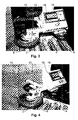
- Fig. 3
- shows a view of the registering wheel arrangement of Fig. 1 with one of the registering wheels in contact with a corner of a stack of items, as seen from the front of the registering wheel arrangement,
- Fig. 4
- shows a view of the registering wheel arrangement of Fig. 1 with a third registering wheel in contact with a curved end part of an item stack,
- Fig. 5
- shows a view of the registering wheel arrangement of Fig. 1 with a second registering wheel in contact with an end part of a vertical stack of items, and
- Fig. 6
- shows a view of an upper part of a grinding cylinder arrangement in an apparatus according to the invention.
- In Fig. 1 is seen a registering wheel arrangement comprising two registering
wheels arms wheel 10 is mounted on anarm 12 which is perpendicular to thearms wheel 10 is representing a vertical row of pressurised air nozzles which are placed at the middle between the grinding cylinders and which are intended for blowing grinding dust away after the grinding operation. The registering wheel arrangement is suspended in a vertical support arm which upwardly, as shown in Fig. 2, is connected with a separate registeringcarriage 14 that may be displaced in transverse direction on a transom which may be displaced along a rollerpath for vertical stacks of laminboards to be ground at the edges. The registering wheel arrangement is suspended in such a way that its pattern of movement corresponds completely to the pattern of movement of the associated grinding cylinders, as the registering wheel arrangement is intended for use in programming the associated control computer. - The machine operator may, without any knowledge of programming the control computer, perform the needed pre-programming by means of the registering wheels arrangement, the movement of which during the programming movements are automatically registered by impulse counters situated on the separate registering carriage, as the operator simultaneously may supplement with certain control commands by means of a
keyboard 16 withdisplay 18, which, for example, may show the current positional co-ordinates. - Most clearly appearing from Figs. 3 and 4, the registering
wheels wheel 2 and the corresponding grinding cylinder are rotating clockwise, whereas the right registering wheel and the associated grinding cylinder rotates counterclockwise. - It is very important that the direction of rotation of the grinding cylinders is correct, particularly when grinding out over an end edge of a side where the direction of rotation of the grinding cylinder, in order to avoid damage at the ends, has to be co-rotating compared with the displacing movement.
- The presetting of the registering
wheels carrier arms
Claims (6)
- A method for edge grinding of plate items in a vertical stack, e.g. laminboards, where a grinding apparatus is used, comprising a number of vertical shafts for a number of abrasive rollers forming vertical grinding cylinders with a length adapted to the height of the stacks of items and which are driven by each their drive motor so that the grinding cylinders may be rotated in each their direction of rotation, which grinding cylinders are suspended in a turning ring by a trolley which is displaceable in the transverse direction relative to a support beam displaceable along a rollerpath for the stacks of items and a fixation device for the stacks of items arranged along the rollerpath, and where there is used a computerised, combined electronic and pneumatic control system, characterized in that the programming of the control computer occurs by means of a separate registering carriage which is arranged to perform the same pattern of movement as the grinding cylinders, and which has a registering wheel representing the respective grinding cylinders and preferably a further registering wheel representing a vertical row of air nozzles, where the registering wheel is moved manually along selected sections of the outer edges of the stacks of items so that the grinding cylinders subsequently are performing the same pattern of movement for performing the desired edge grinding and final blowing off of grinding dust, as suitable means for regulating pressure controlled pressing of the grinding cylinders against the outer edges of the stacks of items are used.
- An apparatus for edge grinding of plate items in a vertical stack, e.g. laminboards, and comprising a number of vertical shafts for a number of abrasive rollers forming vertical grinding cylinders with a length adapted to the height of the stacks of items, and which are driven by each their drive motor so that the grinding cylinders may be rotated in each their direction of rotation, the grinding cylinders being suspended by a turning ring by a trolley which is displaceable in the transverse direction of a support beam displaceable along a rollerpath for the stacks of items and a fixation device for the stacks of items arranged along the rollerpath, and where there is used a computerised, combined electronic and pneumatic control system, characterized in comprising a separate registering carriage which is arranged to perform the same pattern of movement as the grinding cylinders, and which has a registering wheel representing the respective grinding cylinders and preferably a further registering wheel representing a vertical row of air nozzles, registering wheels being arranged to be moved manually with roller contact along selected sections of the outer edges of the stacks of items with the purpose of programming a control computer for the apparatus so that the grinding cylinders subsequently are performing the same pattern of movement for performing the desired edge grinding and final blowing off of grinding dust, as suitable means for regulating pressure controlled pressing of the grinding cylinders against the outer edges of the stacks of items are used.
- An apparatus according to claim 2, characterized in that the means for regulating pressure controlled pressing of the grinding cylinders are constituted by mechanical setting screws with measuring rulers for each of the registering wheels so that the actual location of the point of contact of the registering wheels with the side of the stack of items representing the effective periphery of the grinding cylinders may be preset in dependence on empirical parameters such as type of coating, degree of hardening of coating, rigidity of grinding cylinders, grinding capacity of grinding cylinders etc.
- An apparatus according to claim 2, characterized in that in connection with the registering wheel arrangement, the apparatus comprises a keyboard with display for giving control information such as current rotational speed and for showing current location co-ordinates.
- An apparatus according to claim 2, characterized in that the separate registering carriage comprises impulse counters for registering the current location and configuration of the current stack of items.
- An apparatus according to claim 2, characterized in that at both sides of the rollerpath on which the stack of items is placed during the grinding process, the apparatus comprises holding cylinders that each are arranged to interact with elevating clamping members situated between the rollers of the rollerpath for lifting free the stack of items while this is held by the holding cylinder located at the side of the stack which faces away from the side ground, i.e. the holding cylinder at the opposite side is automatically deactivated when the grinding cylinder is finished with one side.
Applications Claiming Priority (2)
| Application Number | Priority Date | Filing Date | Title |
|---|---|---|---|
| DKPA200001468 | 2000-10-03 | ||
| DK200001468 | 2000-10-03 |
Publications (2)
| Publication Number | Publication Date |
|---|---|
| EP1195227A2 true EP1195227A2 (en) | 2002-04-10 |
| EP1195227A3 EP1195227A3 (en) | 2002-07-17 |
Family
ID=8159761
Family Applications (1)
| Application Number | Title | Priority Date | Filing Date |
|---|---|---|---|
| EP01123493A Withdrawn EP1195227A3 (en) | 2000-10-03 | 2001-09-28 | Method and apparatus for edge grinding of vertically stacked plate items |
Country Status (1)
| Country | Link |
|---|---|
| EP (1) | EP1195227A3 (en) |
Cited By (5)
| Publication number | Priority date | Publication date | Assignee | Title |
|---|---|---|---|---|
| WO2003013787A1 (en) * | 2001-08-06 | 2003-02-20 | Himmer, Nina | Working device and method for working a stack of plate-shaped elements |
| EP1510289A2 (en) * | 2002-08-30 | 2005-03-02 | RoboTool Holding ApS | method for stack grinding |
| ITBO20110288A1 (en) * | 2011-05-20 | 2012-11-21 | Sorbini Srl | EQUIPMENT FOR AUTOMATICALLY REMOVING THE EXCESS OF PAINT FROM THE ENDS OF EDGES WITH DIFFERENT PROFILE, OF PANELS OR OTHER MANUFACTURED PRODUCTS WITH PREVALENT FLAT, WOODEN EXTENSION OR OTHER MATERIALS. |
| CN109202597A (en) * | 2018-10-09 | 2019-01-15 | 浙江花景木业有限公司 | Prepare the edging device of wood floors |
| CN114083626A (en) * | 2021-11-24 | 2022-02-25 | 赵瑞丹 | Furniture wooden board burring device for building |
Citations (3)
| Publication number | Priority date | Publication date | Assignee | Title |
|---|---|---|---|---|
| US4115684A (en) * | 1976-06-17 | 1978-09-19 | Unimation | Portable, programmable manipulator apparatus |
| EP0484674A2 (en) * | 1990-10-05 | 1992-05-13 | Intermac Srl | Process for the automatic machining of edges of glass plates and apparatus for carrying out said process |
| EP1034882A2 (en) * | 1999-03-11 | 2000-09-13 | Karsten Kristiansen | An apparatus for edge grinding plate-like articles in a vertical stack, e.g. laminboards |
-
2001
- 2001-09-28 EP EP01123493A patent/EP1195227A3/en not_active Withdrawn
Patent Citations (3)
| Publication number | Priority date | Publication date | Assignee | Title |
|---|---|---|---|---|
| US4115684A (en) * | 1976-06-17 | 1978-09-19 | Unimation | Portable, programmable manipulator apparatus |
| EP0484674A2 (en) * | 1990-10-05 | 1992-05-13 | Intermac Srl | Process for the automatic machining of edges of glass plates and apparatus for carrying out said process |
| EP1034882A2 (en) * | 1999-03-11 | 2000-09-13 | Karsten Kristiansen | An apparatus for edge grinding plate-like articles in a vertical stack, e.g. laminboards |
Non-Patent Citations (1)
| Title |
|---|
| MUTO S-Y ET AL: "TEACHING AND CONTROL OF ROBOT CONTOUR-TRACKING USING CONTACT POINT DETECTION" PROCEEDINGS OF THE INTERNATIONAL CONFERENCE ON ROBOTICS AND AUTOMATION SAN DIEGO, MAY 8 - 13, 1994, LOS ALAMITOS, IEEE COMP. SOC. PRESS, US, vol. 1 CONF. 11, 8 May 1994 (1994-05-08), pages 674-681, XP000478928 ISBN: 0-8186-5332-9 * |
Cited By (7)
| Publication number | Priority date | Publication date | Assignee | Title |
|---|---|---|---|---|
| WO2003013787A1 (en) * | 2001-08-06 | 2003-02-20 | Himmer, Nina | Working device and method for working a stack of plate-shaped elements |
| EP1510289A2 (en) * | 2002-08-30 | 2005-03-02 | RoboTool Holding ApS | method for stack grinding |
| EP1510289A3 (en) * | 2002-08-30 | 2005-11-09 | RoboTool Holding ApS | method for stack grinding |
| ITBO20110288A1 (en) * | 2011-05-20 | 2012-11-21 | Sorbini Srl | EQUIPMENT FOR AUTOMATICALLY REMOVING THE EXCESS OF PAINT FROM THE ENDS OF EDGES WITH DIFFERENT PROFILE, OF PANELS OR OTHER MANUFACTURED PRODUCTS WITH PREVALENT FLAT, WOODEN EXTENSION OR OTHER MATERIALS. |
| CN109202597A (en) * | 2018-10-09 | 2019-01-15 | 浙江花景木业有限公司 | Prepare the edging device of wood floors |
| CN109202597B (en) * | 2018-10-09 | 2024-03-22 | 山东颐零环保板有限公司 | Edging device for preparing wooden floor |
| CN114083626A (en) * | 2021-11-24 | 2022-02-25 | 赵瑞丹 | Furniture wooden board burring device for building |
Also Published As
| Publication number | Publication date |
|---|---|
| EP1195227A3 (en) | 2002-07-17 |
Similar Documents
| Publication | Publication Date | Title |
|---|---|---|
| CN105538109A (en) | Sander | |
| JPH04300162A (en) | Method of finishing surface and device therefor | |
| CN106925632A (en) | A kind of flexible bending center | |
| US5674110A (en) | Machine and a process for sizing and squaring slabs of materials such as a glass, stone and marble, ceramic tile and the like | |
| KR100363440B1 (en) | Glass processing equipment | |
| EP1195227A2 (en) | Method and apparatus for edge grinding of vertically stacked plate items | |
| US7373733B2 (en) | Heavy machine and method for assisting in aligning a heavy machine | |
| US5807166A (en) | Glass-plate working machine | |
| CN112721432B (en) | A advertisement lithography apparatus for packaging design | |
| JPH10291149A (en) | Angular part device for glass plate | |
| JPH057143B2 (en) | ||
| CN206643756U (en) | A kind of shaft-like workpiece burnishing device | |
| KR100467219B1 (en) | System for finishing edge of steel member | |
| JP3483975B2 (en) | Slab deburring device | |
| US20060089086A1 (en) | Working device and method for working a stack of plate-shaped elements | |
| CN211029647U (en) | Sand blasting equipment for rubber roll core | |
| CN104191361A (en) | Tray locating mechanism for iron casting finishing device and iron casting finishing device | |
| EP0742076B1 (en) | A machine for sizing and squaring slabs of materials such as glass, stone and marble, ceramic tiles and the like | |
| EP0673715B1 (en) | Machine for processing glass plate | |
| JPH03146221A (en) | Coil rotating device | |
| JPH0615146B2 (en) | Method and apparatus for making a ruled surface of a cam | |
| CN210193985U (en) | Fixing device for sand blowing before stainless steel nitriding | |
| KR102656838B1 (en) | Apparatus for Automatic Sanding | |
| JP3903773B2 (en) | Cutting equipment | |
| CN218856501U (en) | Intelligent integrated equipment of angle valve one-stop sand light wire drawing |
Legal Events
| Date | Code | Title | Description |
|---|---|---|---|
| PUAI | Public reference made under article 153(3) epc to a published international application that has entered the european phase |
Free format text: ORIGINAL CODE: 0009012 |
|
| AK | Designated contracting states |
Kind code of ref document: A2 Designated state(s): AT BE CH CY DE DK ES FI FR GB GR IE IT LI LU MC NL PT SE TR |
|
| AX | Request for extension of the european patent |
Free format text: AL;LT;LV;MK;RO;SI |
|
| PUAL | Search report despatched |
Free format text: ORIGINAL CODE: 0009013 |
|
| AK | Designated contracting states |
Kind code of ref document: A3 Designated state(s): AT BE CH CY DE DK ES FI FR GB GR IE IT LI LU MC NL PT SE TR |
|
| AX | Request for extension of the european patent |
Free format text: AL;LT;LV;MK;RO;SI |
|
| RIC1 | Information provided on ipc code assigned before grant |
Free format text: 7B 24B 9/18 A, 7G 05B 19/423 B |
|
| AKX | Designation fees paid | ||
| REG | Reference to a national code |
Ref country code: DE Ref legal event code: 8566 |
|
| STAA | Information on the status of an ep patent application or granted ep patent |
Free format text: STATUS: THE APPLICATION IS DEEMED TO BE WITHDRAWN |
|
| 18D | Application deemed to be withdrawn |
Effective date: 20030118 |