EP1195224A1 - Liquid coolant nozzle for machine tool - Google Patents
Liquid coolant nozzle for machine tool Download PDFInfo
- Publication number
- EP1195224A1 EP1195224A1 EP98961637A EP98961637A EP1195224A1 EP 1195224 A1 EP1195224 A1 EP 1195224A1 EP 98961637 A EP98961637 A EP 98961637A EP 98961637 A EP98961637 A EP 98961637A EP 1195224 A1 EP1195224 A1 EP 1195224A1
- Authority
- EP
- European Patent Office
- Prior art keywords
- liquid coolant
- flow
- nozzle
- peripheral wall
- inner peripheral
- Prior art date
- Legal status (The legal status is an assumption and is not a legal conclusion. Google has not performed a legal analysis and makes no representation as to the accuracy of the status listed.)
- Withdrawn
Links
Images


Classifications
-
- B—PERFORMING OPERATIONS; TRANSPORTING
- B23—MACHINE TOOLS; METAL-WORKING NOT OTHERWISE PROVIDED FOR
- B23Q—DETAILS, COMPONENTS, OR ACCESSORIES FOR MACHINE TOOLS, e.g. ARRANGEMENTS FOR COPYING OR CONTROLLING; MACHINE TOOLS IN GENERAL CHARACTERISED BY THE CONSTRUCTION OF PARTICULAR DETAILS OR COMPONENTS; COMBINATIONS OR ASSOCIATIONS OF METAL-WORKING MACHINES, NOT DIRECTED TO A PARTICULAR RESULT
- B23Q11/00—Accessories fitted to machine tools for keeping tools or parts of the machine in good working condition or for cooling work; Safety devices specially combined with or arranged in, or specially adapted for use in connection with, machine tools
- B23Q11/10—Arrangements for cooling or lubricating tools or work
-
- B—PERFORMING OPERATIONS; TRANSPORTING
- B23—MACHINE TOOLS; METAL-WORKING NOT OTHERWISE PROVIDED FOR
- B23Q—DETAILS, COMPONENTS, OR ACCESSORIES FOR MACHINE TOOLS, e.g. ARRANGEMENTS FOR COPYING OR CONTROLLING; MACHINE TOOLS IN GENERAL CHARACTERISED BY THE CONSTRUCTION OF PARTICULAR DETAILS OR COMPONENTS; COMBINATIONS OR ASSOCIATIONS OF METAL-WORKING MACHINES, NOT DIRECTED TO A PARTICULAR RESULT
- B23Q11/00—Accessories fitted to machine tools for keeping tools or parts of the machine in good working condition or for cooling work; Safety devices specially combined with or arranged in, or specially adapted for use in connection with, machine tools
- B23Q11/08—Protective coverings for parts of machine tools; Splash guards
- B23Q11/0858—Protective coverings for parts of machine tools; Splash guards using a liquid bath or a liquid curtain
-
- B—PERFORMING OPERATIONS; TRANSPORTING
- B23—MACHINE TOOLS; METAL-WORKING NOT OTHERWISE PROVIDED FOR
- B23Q—DETAILS, COMPONENTS, OR ACCESSORIES FOR MACHINE TOOLS, e.g. ARRANGEMENTS FOR COPYING OR CONTROLLING; MACHINE TOOLS IN GENERAL CHARACTERISED BY THE CONSTRUCTION OF PARTICULAR DETAILS OR COMPONENTS; COMBINATIONS OR ASSOCIATIONS OF METAL-WORKING MACHINES, NOT DIRECTED TO A PARTICULAR RESULT
- B23Q11/00—Accessories fitted to machine tools for keeping tools or parts of the machine in good working condition or for cooling work; Safety devices specially combined with or arranged in, or specially adapted for use in connection with, machine tools
- B23Q11/10—Arrangements for cooling or lubricating tools or work
- B23Q11/1076—Arrangements for cooling or lubricating tools or work with a cutting liquid nozzle specially adaptable to different kinds of machining operations
-
- Y—GENERAL TAGGING OF NEW TECHNOLOGICAL DEVELOPMENTS; GENERAL TAGGING OF CROSS-SECTIONAL TECHNOLOGIES SPANNING OVER SEVERAL SECTIONS OF THE IPC; TECHNICAL SUBJECTS COVERED BY FORMER USPC CROSS-REFERENCE ART COLLECTIONS [XRACs] AND DIGESTS
- Y10—TECHNICAL SUBJECTS COVERED BY FORMER USPC
- Y10S—TECHNICAL SUBJECTS COVERED BY FORMER USPC CROSS-REFERENCE ART COLLECTIONS [XRACs] AND DIGESTS
- Y10S29/00—Metal working
- Y10S29/05—Cutting fluid application and debris control
-
- Y—GENERAL TAGGING OF NEW TECHNOLOGICAL DEVELOPMENTS; GENERAL TAGGING OF CROSS-SECTIONAL TECHNOLOGIES SPANNING OVER SEVERAL SECTIONS OF THE IPC; TECHNICAL SUBJECTS COVERED BY FORMER USPC CROSS-REFERENCE ART COLLECTIONS [XRACs] AND DIGESTS
- Y10—TECHNICAL SUBJECTS COVERED BY FORMER USPC
- Y10T—TECHNICAL SUBJECTS COVERED BY FORMER US CLASSIFICATION
- Y10T407/00—Cutters, for shaping
- Y10T407/14—Cutters, for shaping with means to apply fluid to cutting tool
-
- Y—GENERAL TAGGING OF NEW TECHNOLOGICAL DEVELOPMENTS; GENERAL TAGGING OF CROSS-SECTIONAL TECHNOLOGIES SPANNING OVER SEVERAL SECTIONS OF THE IPC; TECHNICAL SUBJECTS COVERED BY FORMER USPC CROSS-REFERENCE ART COLLECTIONS [XRACs] AND DIGESTS
- Y10—TECHNICAL SUBJECTS COVERED BY FORMER USPC
- Y10T—TECHNICAL SUBJECTS COVERED BY FORMER US CLASSIFICATION
- Y10T408/00—Cutting by use of rotating axially moving tool
- Y10T408/44—Cutting by use of rotating axially moving tool with means to apply transient, fluent medium to work or product
-
- Y—GENERAL TAGGING OF NEW TECHNOLOGICAL DEVELOPMENTS; GENERAL TAGGING OF CROSS-SECTIONAL TECHNOLOGIES SPANNING OVER SEVERAL SECTIONS OF THE IPC; TECHNICAL SUBJECTS COVERED BY FORMER USPC CROSS-REFERENCE ART COLLECTIONS [XRACs] AND DIGESTS
- Y10—TECHNICAL SUBJECTS COVERED BY FORMER USPC
- Y10T—TECHNICAL SUBJECTS COVERED BY FORMER US CLASSIFICATION
- Y10T408/00—Cutting by use of rotating axially moving tool
- Y10T408/44—Cutting by use of rotating axially moving tool with means to apply transient, fluent medium to work or product
- Y10T408/46—Cutting by use of rotating axially moving tool with means to apply transient, fluent medium to work or product including nozzle
-
- Y—GENERAL TAGGING OF NEW TECHNOLOGICAL DEVELOPMENTS; GENERAL TAGGING OF CROSS-SECTIONAL TECHNOLOGIES SPANNING OVER SEVERAL SECTIONS OF THE IPC; TECHNICAL SUBJECTS COVERED BY FORMER USPC CROSS-REFERENCE ART COLLECTIONS [XRACs] AND DIGESTS
- Y10—TECHNICAL SUBJECTS COVERED BY FORMER USPC
- Y10T—TECHNICAL SUBJECTS COVERED BY FORMER US CLASSIFICATION
- Y10T409/00—Gear cutting, milling, or planing
- Y10T409/30—Milling
- Y10T409/303976—Milling with means to control temperature or lubricate
- Y10T409/304032—Cutter or work
Definitions
- the present invention relates to a liquid coolant feeding apparatus in a machine tool, such as a cutting machine or grinding machine, particularly to a nozzle for feeding a liquid coolant to a place of contact between a cutter or the like and a workpiece.
- a major factor for minimizing the machining time and machining-induced strain is to enhance contact lubrication between a cutting edge or grinding tool and a workpiece, and frictional heat dissipation or cooling. More specifically, from the viewpoint that the cutting conditions can be improved by imparting a slight amount of superficial weakening, it follows that a liquid coolant, if allowed to enter the main shearing region for cutting from all directions and adsorbed by the generated microscopic cracks or air gaps, would lower the surface energy to prevent re-adhesion. Such brittleness effect in shearing regions is very useful in that it increases the shearing angle, decreases the thickness of chips and saves the cutting force.
- the centrifugal force of the veil of liquid coolant can be reduced by eliminating the helical rotation.
- a nozzle construction which is designed to discharge a liquid coolant downward through its circulatory nozzle port without a circumferential twist angle, is used it follows that a foreign substance clogging in the nozzle port or thereabouts would result in the liquid veil which is formed of discharged liquid coolant reaching the workpiece surface with a cut or slit formed from the clogging in the veil. (In this respect, if the liquid veil is helically rotating, the slit will disappear due to a mixable helical current in the nozzle construction or immediately below the nozzle port.)
- an object of the present invention is to provide a nozzle construction designed so that even if a waterfall-like veil of discharged liquid coolant is helically rotating, the nozzle decreases the centrifugal force to ensure that the greater part of the liquid coolant reaching a workpiece's surface is directed to the center.
- the present invention provides an annular or polygonal frame-like nozzle for liquid coolant adapted to be installed above a cutter edge such as a milling tool, grinding tool or drill fixed on a vertical main shaft with said nozzle being disposed coaxially with said main shaft and being directed downward, said nozzle comprising:
- the liquid coolant flow moves from the inside channel to the outside channel of the nozzle structure, said channels having a trap or hook construction whereby the liquid coolant flow is formed into a fine turbulent current or a particulate current, moving through the fluid guide floor and falling for discharge through the inner peripheral edge thereof (nozzle port)
- the liquid coolant flow has its velocity (including rotating speed) decreased by the level difference in the fluid guide floor to have an increased thickness, so that the discharged liquid flow from the nozzle port is effectively pushed (radially inwardly) by the thick flow from behind, falling onto the workpiece surface while decreasing the veil diameter according to the flow rate, and moving mostly toward the center; thus, there is formed a central liquid layer which sufficiently covers the tool, as described above.
- Fig. 1 showing the basic arrangement of a liquid coolant circulation feed system in a machine tool according to the invention
- the numeral 1 denotes a main tank of large capacity for a liquid coolant
- 2 denotes a coolant pump P which, in this case, feeds a liquid coolant having bubbles introduced thereinto by an air gripping action to an annular nozzle 3.
- the liquid coolant nozzle 3 is, e.g., annular, and is so designed that a liquid coolant fed from a pump p 1 to be later described flows downward into an waterfall as a cylindrical or inverted frustoconical surrounding veil 4 of helical currents which are an aggregation of fine turbulent currents preferably having a slight twist angle, thus striking the surface of a workpiece 5.
- the workpiece 5 is cut by a milling tool 7 comprising a full-back cutter, and a main shaft 8 which supports the milling tool 7 extends through the axis of the annular nozzle 3.
- the surrounding veil 4 of liquid coolant is directed, at its lower end striking the surface of the workpiece, toward the center, mostly in the form of a surface current moving radially inwardly, providing an efficient supply to the place of contact (machining region) between the milling tool 7 and the workpiece 5.
- said liquid coolant has its foreign substances, such as oily components and chips, separated and removed therefrom, and then it is returned to said large capacity tank 1 through a spout 12.
- a linear liquid coolant spout flow may be fed thereto from a place adjacent thereto as desired, thereby enhancing drainage after the liquid veil 4 has completed its task.
- the numeral 13 denotes an auxiliary nozzle therefor.
- the liquid coolant to be fed as the surrounding veil 4 may desirably has bubbles introduced thereinto by the air gripping action of the coolant pump 2.
- the liquid coolant fed to the region of contact between the milling tool 7 and the workpiece 5 has a small mass and hence the centrifugal force it receives from the rotation of the tool is low, which means that its permeation into the tool/workpiece contact region is easy; in this case, splashes produced by the bursting of the bubbles are accelerated for easy permeation into microscopic cracks.
- the heat dissipation effected by the bursting of the bubbles is also excellent, and the lubrication, heat dissipation, and cooling enhance the cutting function of the tool, as described above, making it possible to effect cutting with high feed rate by using a carbide tool.
- the heat of cutting is continuously removed by the flow of liquid coolant discharged from the machining region.
- the operation for introducing bubbles into the liquid coolant is effected not only by the air gripping action of the pump 2 but also by the shock of pouring effected, for example, by sufficiently increasing the fall from the spout 14 of the recovery pipe to the separating and recovering tank 11 to the liquid level of said tank 11, and the fall from the spout 12 at the exit from the separating and recovering tank 11 to the liquid level of the large capacity tank 1.
- Fig. 2 shows in detail the sectional construction in the basic embodiment of the annular nozzle 3 for liquid coolant.
- the main portion of the open inner peripheral surface 15a of the annular nozzle 3 is supported on the outer peripheral surface of the main shaft cover 16 of the machine.
- the annular nozzle 3 comprises an inner peripheral wall 15 having said open inner peripheral surface 15a; and an annular structure of metal surrounded by said inner peripheral wall 15, an outer peripheral wall 17, a top wall 17 and a lower frame wall 19.
- a space between the relatively thin upper portion 15b of the inner peripheral wall 15 and the outer peripheral wall 17 immediately below the top wall 18 provides an inlet chamber 20 for the liquid coolant, it being arranged that the liquid coolant from said pump 2 is fed into said chamber 20 through an inlet conduit 21 connected to the top wall 18.
- An upper floor 22 which provides the bottom surface of the inlet chamber 20 has a lower surface which provides a ceiling for the main structure of the nozzle 3.
- An inner flange 23 projecting from the lower portion of the inner peripheral wall.
- vertical guide passages 24 for guiding the liquid coolant from the inlet chamber 20 into the area immediately above the inner flange 23.
- the inner flange 23 comprises a corridor for substantially radially flowing the liquid coolant thereinto through the inlet 24a formed to extend outward through the inner peripheral wall 15 from the lower end of the vertical guide passages 24, an intermediate peripheral wall 25 erected from the outer edge of said corridor for inwardly turning the said radially flowing liquid, and a turnaround ceiling plate 26 having an inner peripheral edge 26a opposed to the periphery of said inner peripheral wall 15, said inner flange supporting an inside channel limited in such turnaround sectional construction.
- This inside channel is the portion which initially imparts particulation and turbulence actions to the liquid coolant in the process of turning and upwardly directing the liquid coolant.
- the ceiling defined by the lower surface of the upper floor 22 serves as a guide surface which causes the liquid coolant flowing out of the opening to flow in a planar radial manner above the ceiling plate 26, while the outer peripheral wall 17 serves as an outside guide surface for bending the planar radial flowing liquid downward to flow downward around the inner flange 23.
- the upper structure constructed by these guide surfaces cooperates with the outer wall surface of the inner flange 23 to form an outside channel. At least one place on one of the wall surfaces which form this outside channel, in this case, at the outer peripheral end of the ceiling, there is formed a circulatory groove 27 for disturbing the flow.
- the sectional shape of this circulatory groove is not limited to the illustrated rectangular shape, but it may be any recessed shape or uneven shape.
- the outside channel terminates as a lower end at the upper step surface 19a of the lower frame wall 19 and connects to an inward channel on the flow guide floor comprising said surface 19a and inside step-down surface 19b.
- the lower surface of the inner flange 23 terminates in a position corresponding to an intermediate portion of the step-down surface 19b of the lower frame wall 19 and connects to the lower end 15c of the inner peripheral wall 15, said lower end having a somewhat reduced outer periphery.
- the lower surface of the inner flange 23 and the lower end 15c of the inner peripheral wall are respectively opposed to the upper step surface 19a and step-down surface 19b of the lower frame wall to limit the channel height, while the peripheral surface of the lower end 15c serves as an upper weir plate corresponding to the level difference 19a/19b of the lower frame wall to suppress the flow velocity of the inward flowing liquid.
- the front end, i.e., inner peripheral end, of the step-down surface 19b of the lower frame wall, is a nozzle port 28 downwardly inclined toward the lowermost front edge (lowermost inner peripheral edge); functionally, it serves as a waterfall opening through which the liquid coolant flows downward.
- a nozzle port 28 downwardly inclined toward the lowermost front edge (lowermost inner peripheral edge); functionally, it serves as a waterfall opening through which the liquid coolant flows downward.
- nozzle port 28 defined above the nozzle port 28 is a sufficient space extending to the main shaft cover 16, so that there is no danger of the waterfall-like downward flow being impeded.
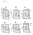
- Fig. 3 shows a combination of horizontal sections illustrating in order the flow of liquid coolant in an annular nozzle as described above.
- the section A shows how a liquid coolant entering the inlet chamber 20 through the inlet conduit 21 flows into one vertical guide passage 24 extending downward from the floor 22 of said chamber and moves downward.
- the section B shows how said liquid coolant flows out of the lower end of said vertical guide passage 24 and into the turbulence inlet 24a which in this case is twisted by an angle of about 60 ° , from which it flows into the inside channel (first turbulence forming region) in the intermediate peripheral wall 25 above the inner flange 23.
- the section C shows the manner in which the liquid coolant flowing upward from the first turbulence forming region flows from above the inner flange 23 through a second turbulence forming region in a sinuous path leading outward.
- the section D shows the presence of an upward turbulence forming pocket 27 located outside the second turbulence forming region.
- the liquid coolant made fully particulate and turbulent flows downward toward the upper step surface 19a of the lower frame wall through the outside channel between the outer peripheral wall 17 and the flange wall 25 shown in the section B.
- the section E it flows from the upper step surface 19a to the step-down surface 19b and, as described above, it strikes the lower end 15c of the inner peripheral wall (Fig. 2) above the step-down surface 19b and is thereby decelerated, flowing downward in a waterfall fashion through the nozzle port 28 as shown in the section F.
- Figs. 4 and 5 show in detail a substantially conical/surrounding veil 4 made of waterfall-like liquid coolant discharged from the annular nozzle shown in Figs. 2 and 3, and the state of a weak helically and radially inward surface flow formed of the greater part of said surrounding veil.
- Fig. 4 even if the liquid coolant discharged as the surrounding veil 4 is discharged approximately directly downward from the nozzle port 28, it has its centrifugal force reduced by the function of decelerating the circulatory component by the lower end 15c of the inner peripheral wall (Fig.
- the radially inward flow 31 shown in solid lines is opposite in direction to the radial flow 32 shown in broken lines.
- the flow of liquid coolant has been made fully particulate when passing through the turbulence forming regions located at two places in the nozzle, as described above, it is presumed that the latter 32 turns around as if sliding over the layer of the former 31, thus forming a turnaround flow flux.
- the liquid coolant is a relatively thick-walled flow, there is no drawback that, as in the conventional nozzle, the liquid coolant strikes the cutting edge of the tool 7 and is bounded back while leaving the chips behind to allow them to cut into the portion being machined.
- Fig. 6 is a fragmentary sectional view showing an annular nozzle according to another embodiment.
- This annular nozzle 33 is the same in construction as the nozzle 3 shown in Figs. 2 and 3 except that the lower framework 34 is of the multistep type and that the lower end of the inner peripheral wall 15' is flush with the lower end of the inner flange 23.
- This lower framework 34 comprises a shelf-like upper step portion 34a radially inwardly projecting from the lower end of the outer peripheral wall 17 and converging, a shelf-like lower step portion 34b likewise radially inwardly projecting and spaced downward from said upper step portion 34a and converging, and an intermediate plate 34c comprising an outer peripheral portion positioned in a spacing between said upper and lower step portions 34a and 34b and an inner peripheral portion projecting from said spacing and converging.
- This intermediate plate 34c is an independent annular plate and suspended from the upper step portion 34a as by flat head screws 35.
- the lower framework 34 serving as a channel guide floor forms a first level difference by a fall from the inner peripheral edge of the upper step portion 34a to the intermediate plate 34c, a second level difference by a fall from the outer peripheral edge of the intermediate plate 34c to the lower step portion 34b, and a first circulatory waterfall opening by the inner peripheral edge of the intermediate plate 34c, and uses said lower step portion 34b as a flow guide floor for the liquid coolant turned around inwardly from said second level difference, and the inner terminal edge thereof as a second circulatory waterfall opening positioned somewhat more outward than said first circulatory waterfall opening.
- the inner terminal end of the lower step portion 34b terminates in radial position short of the inner end of the intermediate plate 34c, it forms a nozzle port of larger diameter, through which the liquid coolant also flows downward like a waterfall.
- this outside downflow portion changes its course to the inward direction as it bypasses the outer peripheral end of the intermediate plate 34c, it consumes its centrifugal force and is rather accelerated inwardly; therefore, after the liquid coolant has become the waterfall-like downflow veil, the action to reduce the diameter of the veil cross-section is stronger. Therefore, the nozzle 33 of this embodiment has a greater ability to converge the inverted cone of liquid coolant than the nozzle 3 in the fundamental embodiment.
- Fig. 7 shows what behavior the surrounding veil of liquid coolant from the nozzle exhibits in the case where a relatively long quill 36 protrusively holding the tool 7 is protruded itself from the nozzle by a significant length e.g., 600 mm, without the direct facing of the nozzle 3 or 33 having an internal structure as shown in Figure 2, 3 or 6, to the workpiece as shown in Figures 1 and 4.
- the surrounding veil 4 of liquid coolant strikes against the middle cylindrical surface of the quill 36 by converging into a substantial inverted conical form, and downwardly flows along the cylindrical surface, surroundingly.
- the downward flow of liquid coolant substantially maintains its finely particle-like turbulency and concentrically surrounding capability, even it has fallen out of the lower end of the quill 40 to rush into the space in just front of the contact place of the tool with the workpiece. It is confirmed therefore, that the flow of the coolant liquid is efficiently supplied to the contact place of the tool with the workpiece. It is predicted that the protruded length of the quill 36 from the nozzle is allowable up to 1 - 1.5 mm. As a result, the invention is applicable to the quill-supplement system as described above to effectively machine for various products, such as a product having a deep hole.
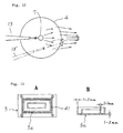
- Figs. 8 A and B show two forms in which the internal nozzle construction shown in Figs. 2, 3 and 6 is build in similar figures within a square frame 37; one in which the final nozzle port alone is in the form of a circle 38, and the other in which it still has a similar square 39.
- Test results have shown that if a waterfall-like surrounding veil of liquid coolant is allowed, in a suitable amount, to sufficiently converge toward a workpiece, the cooling, lubricating and chip recovering effects, and hence improvements in machining accuracy and rate, and cutter life, etc., are substantially the same as in the annular nozzle described above. Further, the modification of a nozzle shown in Fig.
- 8C comprises an oval frame 40, an inner structure of the substantially similar form to the frame 40 therein, and a final nozzle port of the frame in circular form 38'. From this modification, substantially the same effect as the annular nozzle is also obtained. Therefore, it is considered as to a generally elliptic frame again to have the same effect.
- Fig. 9 shows examples in which in the annular and square frame nozzles described above, mainly the second turbulence forming portion in the sectional constructions shown in Figs. 2 and 6 are variously modified.
- the ceiling above the inner flange 23 is formed with triangular undulating ridges 27a in lieu of the flow agitating circulatory groove, i.e., the recess 27 of rectangular cross-section (Figs. 2 and 6)in the preceding embodiment.
- the ceiling is formed with a recess 27b similar to the recess 27 in an intermediate position short of the outer peripheral wall 17.
- the ceiling is formed with a recess 27c positioned in contact with the inner peripheral wall 15.
- a recess 27d is formed with a recess 27d
- a recess 27e is formed in a position which is somewhat below the level of the upper end of the outer peripheral wall 17.
- the position of a recess 27 is the same as in the fundamental embodiment, and the liquid coolant inlet to the space above the inner flange 23 is provided by the lower end 24b of the vertical guide passage 24, opening to the ceiling above the inner flange 23.
- the flow agitating recesses have been varied in position and cross-sectional shape but have been observed to produce the same flow agitating effect so long as they are formed in the ceiling which is the back of the upper floor 22 or in the inner surface of the outer peripheral wall and with substantially the same recess depth and volume as in said circulatory groove 27. It is considered by analogy with this that the same effect would be obtained even when a recess is formed in the peripheral wall (intermediate peripheral wall 25 of the inner flange 23.
- this arrangement is capable of meeting the limitation which does not allow the thickness of the inner peripheral portion to be increased from the viewpoint of nozzle design though the turbulence forming effect is somewhat decreased.
- the present invention provides a nozzle construction arranged in the manner described above which effects liquid coolant feeding ensuring excellent lubrication and cooling, and good discharging characteristic of chips, making it possible to perform a high speed, high precision cutting or lathing operation while feeding a liquid coolant which flows smoothly.
- the machining rate can be increased to a value 3 - 7 times, preferably a value 5 - 25 times in the case of an end mill machine as high as in the case of using a conventional nozzle; thus, the economic effect brought about thereby is very great.
- a reduction in the cost of cutting oil and a large reduction in the cost for washing the tank and treating the drained waste can be expected; thus, the invention provides immeasurable effects in increase of efficiency, abatement of environmental pollution, labor saving, etc.
- a mixture of water and rust-preventive agent alone may be used as a liquid coolant to perform cutting operation.
Landscapes
- Engineering & Computer Science (AREA)
- Mechanical Engineering (AREA)
- Auxiliary Devices For Machine Tools (AREA)
Abstract

Description

Claims (5)
- A nozzle for liquid coolant in a machine tool in the form of an annular or polygonal frame-like nozzle for liquid coolant disposed above a machining tool, such as a milling tool, grinding tool or drill, connected to a vertical main shaft such that the nozzle is coaxial with said main shaft and directed downward, comprising:a) an inner peripheral wall;b) an inner flange for inside channel support comprising a corridor block for allowing a liquid coolant flowing in through an inlet port formed directly in or close to said inner peripheral wall to flow substantially radially, an intermediate peripheral wall extending upright from the outer edge of said corridor block so as to cause the radially flowing liquid to turn around inward, and a turnaround top plate having an inner peripheral edge opposed to the periphery of said inner peripheral wall to define an opening to allow said inwardly turned-around flowing liquid to flow out upward through said opening along said inner peripheral wall;c) an upper framework which comprises a ceiling formed above said top plate to serve as a guide surface for allowing the liquid coolant flowing out upward through said opening to flow in a planar radial manner, and an outer peripheral wall serving as an outside guide surface for downwardly bending said planar radial flowing liquid to allow the latter to flow downward around the periphery of said flange, and which cooperates with the outer wall surface of said flange to define an outside channel, wherein the wall surface which forms the outside channel is formed in at least one place thereon with a flow agitating recess or a ridge/recess combination, andd) a lower framework which includes outer and inner peripheral edges connected to the lower end of said outer peripheral wall positioned below said inner flange, and at least one level difference present intermediate between said inner and outer peripheral edges, and which forms a flow guide floor by which the liquid coolant reaching the lower end of said outer peripheral wall is guided radially inward through said level difference,e) the arrangement being such that the liquid coolant is allowed to flow downward with the inner peripheral edge of said flow guide floor defining a circulatory waterfall opening, thereby forming a cylindrical or downwardly tapering conical waterfall-like liquid coolant veil surrounding said cutter.
- A nozzle for liquid coolant as set forth in Claim 1, characterized in that the inlet port formed directly in or close to said inner peripheral wall is adapted to discharge the liquid coolant along the corridor block of said radial bracket , not in a purely radial manner but with a predetermined transverse twist angle.
- A nozzle for liquid coolant as set forth in Claim 1 or 2, characterized in that said flow agitating recess or ridge/recess combination is formed in at least one place on said ceiling or outer peripheral wall of said upper framework.
- A nozzle for liquid coolant as set forth in any one of Claims 1 through 3, characterized in that the root portion of the back of said inner flange is formed as a depending block corresponding to the at least one level difference of said flow guide floor, said depending block being adapted to serve as an upper weir which causes forced falling of the radially inward liquid coolant flow past said level difference.
- A nozzle for liquid coolant as set forth in Claim 1 through 4, characterized in that the flow guide floor of said lower framework comprises an upper step portion radially inwardly projecting from the lower end edge of said outer peripheral wall and converging, a lower step portion radially inwardly projecting and converging and spaced downward from said upper step portion, and an intermediate plate comprising an outer peripheral portion disposed in a spacing between said upper and lower step portions and an inner peripheral portion projecting from said spacing and converging, wherein a first level difference is defined by a fall extending from the inner peripheral end edge of said upper step portion to said intermediate plate, while a second level difference is defined by a fall extending from the outer peripheral end edge of said intermediate plate to said lower step portion, the inner peripheral end edge of said intermediate plate defining a first circulatory waterfall opening, said lower step portion being adapted to serve as a flow guide floor for the liquid coolant flow which is turned around inwardly from said second level difference, the inner terminal end edge thereof being used to define a second circulatory waterfall opening positioned somewhat outwardly of said first circulatory waterfall opening.
Applications Claiming Priority (1)
| Application Number | Priority Date | Filing Date | Title |
|---|---|---|---|
| PCT/JP1998/005997 WO2000040366A1 (en) | 1998-12-28 | 1998-12-28 | Liquid coolant nozzle for machine tool |
Publications (2)
| Publication Number | Publication Date |
|---|---|
| EP1195224A1 true EP1195224A1 (en) | 2002-04-10 |
| EP1195224A4 EP1195224A4 (en) | 2005-04-13 |
Family
ID=14209761
Family Applications (1)
| Application Number | Title | Priority Date | Filing Date |
|---|---|---|---|
| EP98961637A Withdrawn EP1195224A4 (en) | 1998-12-28 | 1998-12-28 | Liquid coolant nozzle for machine tool |
Country Status (8)
| Country | Link |
|---|---|
| US (1) | US6382887B1 (en) |
| EP (1) | EP1195224A4 (en) |
| JP (1) | JP4310048B2 (en) |
| KR (1) | KR100572205B1 (en) |
| CN (1) | CN1104305C (en) |
| AU (1) | AU1691999A (en) |
| CA (1) | CA2356423A1 (en) |
| WO (1) | WO2000040366A1 (en) |
Cited By (3)
| Publication number | Priority date | Publication date | Assignee | Title |
|---|---|---|---|---|
| US7384329B2 (en) | 2006-05-23 | 2008-06-10 | Saint-Gobain Abrasives Technology Company | Coolant delivery system for grinding tools |
| EP3208037A1 (en) | 2016-02-22 | 2017-08-23 | ISOG Technology GmbH & Co. KG | Nozzle carrier for a tool grinding machine |
| IT202000020470A1 (en) * | 2020-08-26 | 2022-02-26 | Zrn S R L | COOLANT DISTRIBUTION DEVICE FOR LATHE DRIVE TOOL UNIT AND DRIVE TOOL UNIT |
Families Citing this family (19)
| Publication number | Priority date | Publication date | Assignee | Title |
|---|---|---|---|---|
| US6772042B1 (en) * | 2001-05-14 | 2004-08-03 | Dimensional Control, Inc. | Programmable coolant nozzle system |
| JP3626947B2 (en) * | 2002-08-14 | 2005-03-09 | ファナック株式会社 | Machine tool chips and cutting fluid splash prevention device |
| CA2421459A1 (en) * | 2003-03-10 | 2004-09-10 | Darrin Eugene Smith | Rotor for spraying coolant onto a cutter |
| US7582004B2 (en) * | 2003-07-11 | 2009-09-01 | United Technologies Corporation | Coolant nozzle |
| JP2006239795A (en) * | 2005-03-02 | 2006-09-14 | Kyocera Corp | Manufacturing method of semiconductor substrate |
| CN100513067C (en) * | 2005-05-30 | 2009-07-15 | 铨宝工业股份有限公司 | Cutting fluid nozzle for use with a machine tool |
| JP2010110867A (en) * | 2008-11-07 | 2010-05-20 | Mitsubishi Heavy Ind Ltd | Machine tool |
| FR2939060B1 (en) * | 2008-11-28 | 2010-12-17 | Eads Europ Aeronautic Defence | TOOL HOLDER HAVING COOLING MEANS |
| JP5674837B2 (en) * | 2013-02-21 | 2015-02-25 | ファナック株式会社 | Machine tool with a cutting fluid channel with the top of the channel open |
| CN105081491A (en) | 2014-05-15 | 2015-11-25 | 通用电气公司 | Machining system and cutter fixing device thereof |
| DE102016217344A1 (en) * | 2016-09-12 | 2018-03-15 | Deckel Maho Pfronten Gmbh | COOLANT ACCUMULATOR AND GRINDING TOOL WITH A COOLANT ACCELERATOR FOR A MACHINE TOOL |
| US12179299B2 (en) * | 2018-08-07 | 2024-12-31 | Illinois Tool Works Inc. | Machine tool with recirculating coolant filtration system |
| JP6810113B2 (en) * | 2018-09-07 | 2021-01-06 | ファナック株式会社 | Machine Tools |
| JP7399635B2 (en) | 2019-06-24 | 2023-12-18 | シチズン時計株式会社 | Coolant supply equipment and machine tools |
| JP6850387B1 (en) * | 2020-05-26 | 2021-03-31 | Dmg森精機株式会社 | Machine Tools |
| CN111390641B (en) * | 2020-06-08 | 2020-09-22 | 佛山市南海富大精密机械有限公司 | Five-axis linkage numerical control machining center |
| WO2022056723A1 (en) * | 2020-09-16 | 2022-03-24 | Illinois Tool Works Inc. | Standpipe recirculation systems for material removal machines |
| WO2024218965A1 (en) * | 2023-04-21 | 2024-10-24 | ファナック株式会社 | Nozzle |
| CN121223148A (en) * | 2025-09-02 | 2025-12-30 | 江苏鑫晟发科技有限公司 | An apparatus and method for milling automotive body parts |
Family Cites Families (11)
| Publication number | Priority date | Publication date | Assignee | Title |
|---|---|---|---|---|
| EP0212195B1 (en) * | 1985-07-16 | 1990-03-28 | Starrfräsmaschinen AG | Dust decrease and chip transferring and apparatus on a machine tool work station |
| US4778315A (en) * | 1986-09-26 | 1988-10-18 | The Boeing Company | Chip removal and tool lubricating device and method |
| JPS6456940A (en) | 1987-08-28 | 1989-03-03 | Hitachi Ltd | Idle revolution speed controller for engine |
| JPS6456940U (en) * | 1987-10-05 | 1989-04-10 | ||
| JPH04176537A (en) | 1990-11-07 | 1992-06-24 | Hamai Sangyo Kk | Machine tool |
| US5245152A (en) * | 1992-06-09 | 1993-09-14 | Klein Tools, Inc. | Dielectric fluid dust extraction system for electric discharge machine |
| JPH0755437B2 (en) * | 1992-08-06 | 1995-06-14 | 富士重工業株式会社 | Cooling dust collector for machine tools |
| JPH0725007A (en) | 1993-07-09 | 1995-01-27 | Canon Inc | Inkjet recording device |
| JPH0751981A (en) * | 1993-08-13 | 1995-02-28 | Taiho Kogyo Co Ltd | Cutting method and its equipment |
| US6071047A (en) * | 1996-02-15 | 2000-06-06 | Zeta Heiwa Ltd. | Method and apparatus for feeding coolant liquid and separating and recovering it in cutting machine and grinding machine |
| US6036412A (en) * | 1998-03-24 | 2000-03-14 | Dalla; Joseph E. | Coolant and chip removal apparatus for milling operations |
-
1998
- 1998-12-28 CA CA002356423A patent/CA2356423A1/en not_active Abandoned
- 1998-12-28 JP JP2000592103A patent/JP4310048B2/en not_active Expired - Fee Related
- 1998-12-28 US US09/623,077 patent/US6382887B1/en not_active Expired - Fee Related
- 1998-12-28 WO PCT/JP1998/005997 patent/WO2000040366A1/en not_active Ceased
- 1998-12-28 KR KR1020017008194A patent/KR100572205B1/en not_active Expired - Fee Related
- 1998-12-28 AU AU16919/99A patent/AU1691999A/en not_active Abandoned
- 1998-12-28 CN CN98814378A patent/CN1104305C/en not_active Expired - Fee Related
- 1998-12-28 EP EP98961637A patent/EP1195224A4/en not_active Withdrawn
Cited By (4)
| Publication number | Priority date | Publication date | Assignee | Title |
|---|---|---|---|---|
| US7384329B2 (en) | 2006-05-23 | 2008-06-10 | Saint-Gobain Abrasives Technology Company | Coolant delivery system for grinding tools |
| EP3208037A1 (en) | 2016-02-22 | 2017-08-23 | ISOG Technology GmbH & Co. KG | Nozzle carrier for a tool grinding machine |
| US10478942B2 (en) | 2016-02-22 | 2019-11-19 | ISOG Technology GmbH | Nozzle carrier for a tool grinding machine |
| IT202000020470A1 (en) * | 2020-08-26 | 2022-02-26 | Zrn S R L | COOLANT DISTRIBUTION DEVICE FOR LATHE DRIVE TOOL UNIT AND DRIVE TOOL UNIT |
Also Published As
| Publication number | Publication date |
|---|---|
| KR100572205B1 (en) | 2006-04-18 |
| AU1691999A (en) | 2000-07-24 |
| CN1104305C (en) | 2003-04-02 |
| CA2356423A1 (en) | 2000-07-13 |
| KR20020005569A (en) | 2002-01-17 |
| US6382887B1 (en) | 2002-05-07 |
| WO2000040366A1 (en) | 2000-07-13 |
| EP1195224A4 (en) | 2005-04-13 |
| CN1327404A (en) | 2001-12-19 |
| JP4310048B2 (en) | 2009-08-05 |
Similar Documents
| Publication | Publication Date | Title |
|---|---|---|
| US6382887B1 (en) | Nozzle for liquid coolant in a machine tool | |
| JP3354156B2 (en) | Method and apparatus for supplying coolant liquid in cutting machine and grinding machine | |
| JPWO2000040366A1 (en) | Coolant nozzle for machine tools | |
| JPWO1997029882A1 (en) | Method and device for supplying, separating and recovering coolant in cutting and grinding machines | |
| CN1101295C (en) | Processing method and mist supply device used therein | |
| KR100331944B1 (en) | Liquid coater | |
| CN110238466B (en) | Electric arc micro-explosion internal and external liquid flushing device and processing equipment | |
| CN108406025A (en) | Microcapillary electrolysis cuts big thickness workpiece method and device | |
| CN1122735A (en) | Discharge nozzle for continuous casting | |
| JP2007069236A (en) | Method for continuous casting of molten metal | |
| CN205887197U (en) | Decanter centrifuge | |
| JP2008030069A (en) | Method for continuous casting of molten metal | |
| CN213033806U (en) | Reamer for processing through hole | |
| CN121342147B (en) | Hydraulic rotary synchronous separation and purification device for cutting fluid for workpiece processing | |
| CN211332136U (en) | Electric arc micro-explosion and cutting combined machining device | |
| JPH0236668Y2 (en) | ||
| CN223749162U (en) | A tool reverse chip removal structure | |
| CN205887196U (en) | Decanter centrifuge | |
| JP2000094261A (en) | Method and device for preventing dust scattering | |
| CN220836117U (en) | Centrifugal filter | |
| JP2007216374A (en) | Immersion milling device | |
| CN212042695U (en) | Inner water outlet chip blocking device | |
| EP3569359A1 (en) | Abrasive heads with inserted jet | |
| CN2673548Y (en) | Processing groove of high speed small hole discharge processing device | |
| HK1018757A (en) | Method and apparatus for supplying and separating recovering liquid coolant for cutting machines and grinding machines |
Legal Events
| Date | Code | Title | Description |
|---|---|---|---|
| PUAI | Public reference made under article 153(3) epc to a published international application that has entered the european phase |
Free format text: ORIGINAL CODE: 0009012 |
|
| 17P | Request for examination filed |
Effective date: 20010727 |
|
| AK | Designated contracting states |
Kind code of ref document: A1 Designated state(s): BE CH DE FR GB IT LI NL SE |
|
| RIN1 | Information on inventor provided before grant (corrected) |
Inventor name: NAKAI, YOSHIKAZU |
|
| RAP1 | Party data changed (applicant data changed or rights of an application transferred) |
Owner name: ZETA HEIWA LTD. |
|
| RAP1 | Party data changed (applicant data changed or rights of an application transferred) |
Owner name: HOEI KOGYO CO., LTD. |
|
| RAP1 | Party data changed (applicant data changed or rights of an application transferred) |
Owner name: HOEI KOGYO CO., LTD. Owner name: ZETA HEIWA LTD. |
|
| A4 | Supplementary search report drawn up and despatched |
Effective date: 20050302 |
|
| RIC1 | Information provided on ipc code assigned before grant |
Ipc: 7B 23Q 11/08 B Ipc: 7B 23Q 11/00 B Ipc: 7B 23Q 11/10 A |
|
| STAA | Information on the status of an ep patent application or granted ep patent |
Free format text: STATUS: THE APPLICATION IS DEEMED TO BE WITHDRAWN |
|
| 18D | Application deemed to be withdrawn |
Effective date: 20060411 |