EP1194747B2 - Coriolis flowmeter having a casing with a protective outer layer - Google Patents
Coriolis flowmeter having a casing with a protective outer layer Download PDFInfo
- Publication number
- EP1194747B2 EP1194747B2 EP00941336.0A EP00941336A EP1194747B2 EP 1194747 B2 EP1194747 B2 EP 1194747B2 EP 00941336 A EP00941336 A EP 00941336A EP 1194747 B2 EP1194747 B2 EP 1194747B2
- Authority
- EP
- European Patent Office
- Prior art keywords
- casing
- veneer
- flow tube
- coriolis flowmeter
- affixed
- Prior art date
- Legal status (The legal status is an assumption and is not a legal conclusion. Google has not performed a legal analysis and makes no representation as to the accuracy of the status listed.)
- Expired - Lifetime
Links
- 230000001681 protective effect Effects 0.000 title 1
- 239000000463 material Substances 0.000 claims description 51
- 238000010438 heat treatment Methods 0.000 claims description 9
- 238000009413 insulation Methods 0.000 claims description 8
- 239000010935 stainless steel Substances 0.000 claims description 5
- 229910001220 stainless steel Inorganic materials 0.000 claims description 5
- RTAQQCXQSZGOHL-UHFFFAOYSA-N Titanium Chemical compound [Ti] RTAQQCXQSZGOHL-UHFFFAOYSA-N 0.000 claims description 4
- 239000010936 titanium Substances 0.000 claims description 4
- 229910052719 titanium Inorganic materials 0.000 claims description 4
- 229910000975 Carbon steel Inorganic materials 0.000 claims description 3
- 239000010962 carbon steel Substances 0.000 claims description 3
- 230000010355 oscillation Effects 0.000 claims description 3
- 230000007797 corrosion Effects 0.000 description 15
- 238000005260 corrosion Methods 0.000 description 15
- 230000008602 contraction Effects 0.000 description 8
- 239000012530 fluid Substances 0.000 description 5
- 125000006850 spacer group Chemical group 0.000 description 4
- 239000004020 conductor Substances 0.000 description 3
- 238000000034 method Methods 0.000 description 3
- 230000001133 acceleration Effects 0.000 description 1
- 239000002253 acid Substances 0.000 description 1
- 238000005452 bending Methods 0.000 description 1
- 230000009977 dual effect Effects 0.000 description 1
- 230000003670 easy-to-clean Effects 0.000 description 1
- 230000000694 effects Effects 0.000 description 1
- 239000004615 ingredient Substances 0.000 description 1
- 239000011810 insulating material Substances 0.000 description 1
- 238000004519 manufacturing process Methods 0.000 description 1
- 229910052751 metal Inorganic materials 0.000 description 1
- 239000002184 metal Substances 0.000 description 1
- 150000002739 metals Chemical class 0.000 description 1
- 230000000135 prohibitive effect Effects 0.000 description 1
Images

Classifications
-
- G—PHYSICS
- G01—MEASURING; TESTING
- G01F—MEASURING VOLUME, VOLUME FLOW, MASS FLOW OR LIQUID LEVEL; METERING BY VOLUME
- G01F1/00—Measuring the volume flow or mass flow of fluid or fluent solid material wherein the fluid passes through a meter in a continuous flow
- G01F1/76—Devices for measuring mass flow of a fluid or a fluent solid material
- G01F1/78—Direct mass flowmeters
- G01F1/80—Direct mass flowmeters operating by measuring pressure, force, momentum, or frequency of a fluid flow to which a rotational movement has been imparted
- G01F1/84—Coriolis or gyroscopic mass flowmeters
- G01F1/8409—Coriolis or gyroscopic mass flowmeters constructional details
- G01F1/8413—Coriolis or gyroscopic mass flowmeters constructional details means for influencing the flowmeter's motional or vibrational behaviour, e.g., conduit support or fixing means, or conduit attachments
- G01F1/8418—Coriolis or gyroscopic mass flowmeters constructional details means for influencing the flowmeter's motional or vibrational behaviour, e.g., conduit support or fixing means, or conduit attachments motion or vibration balancing means
-
- G—PHYSICS
- G01—MEASURING; TESTING
- G01F—MEASURING VOLUME, VOLUME FLOW, MASS FLOW OR LIQUID LEVEL; METERING BY VOLUME
- G01F1/00—Measuring the volume flow or mass flow of fluid or fluent solid material wherein the fluid passes through a meter in a continuous flow
- G01F1/76—Devices for measuring mass flow of a fluid or a fluent solid material
- G01F1/78—Direct mass flowmeters
- G01F1/80—Direct mass flowmeters operating by measuring pressure, force, momentum, or frequency of a fluid flow to which a rotational movement has been imparted
- G01F1/84—Coriolis or gyroscopic mass flowmeters
- G01F1/845—Coriolis or gyroscopic mass flowmeters arrangements of measuring means, e.g., of measuring conduits
- G01F1/8468—Coriolis or gyroscopic mass flowmeters arrangements of measuring means, e.g., of measuring conduits vibrating measuring conduits
- G01F1/849—Coriolis or gyroscopic mass flowmeters arrangements of measuring means, e.g., of measuring conduits vibrating measuring conduits having straight measuring conduits
-
- G—PHYSICS
- G01—MEASURING; TESTING
- G01F—MEASURING VOLUME, VOLUME FLOW, MASS FLOW OR LIQUID LEVEL; METERING BY VOLUME
- G01F15/00—Details of, or accessories for, apparatus of groups G01F1/00 - G01F13/00 insofar as such details or appliances are not adapted to particular types of such apparatus
- G01F15/14—Casings, e.g. of special material
-
- G—PHYSICS
- G01—MEASURING; TESTING
- G01F—MEASURING VOLUME, VOLUME FLOW, MASS FLOW OR LIQUID LEVEL; METERING BY VOLUME
- G01F15/00—Details of, or accessories for, apparatus of groups G01F1/00 - G01F13/00 insofar as such details or appliances are not adapted to particular types of such apparatus
- G01F15/16—Diaphragms; Bellows; Mountings therefor
Definitions
- This invention relates to a casing enclosing a Coriolis flowmeter. More particularly, the present invention relates to a veneer on the outside of the casing that allows the casing to be used in sanitary applications. Still more particularly, the present invention relates to a veneer that encloses a casing and that provides a sanitary and/or corrosion proof surface for the casing.
- Coriolis effect mass flowmeters to measure mass flow and other information of materials flowing through a pipeline as disclosed in U.S. Patent No. 4,491,025 issued to J.E. Smith, et al. of January 1, 1985 and Re. 31,450 to J.E. Smith of February 11, 1982 .
- These flowmeters have one or more flow tubes of a curved or a straight configuration.
- Each flow tube configuration in a Coriolis mass flowmeter has a set of natural vibration modes, which may be of a simple bending, torsional, radial, or coupled type.
- Each flow tube is driven to oscillate at resonance in one of these natural modes.
- the natural vibration modes of the vibrating, material filled systems are defined in part by the combined mass of the flow tubes and the material within the flow tubes. Material flows into the flowmeter from a connected pipeline on the inlet side of the flowmeter. The material is then directed through the flow tube or flow tubes and exits the flowmeter to a pipeline connected on the outlet side.
- a driver applies a vibrational force to the flow tube.
- the force causes the flow tube to oscillate.
- all points along a flow tube oscillate with an identical phase.
- Coriolis accelerations cause each point along the flow tube to have a different phase with respect to other points along the flow tube.
- the phase on the inlet side of the flow tube lags the driver, while the phase on the outlet side leads the driver.
- Sensors at two different points on the flow tube produce sinusoidal signals representative of the motion of the flow tube at the two points.
- a phase difference of the two signals received from the sensors is calculated in units of time. The phase difference between the two sensor signals is proportional to the mass flow rate of the material flowing through the flow tube or flow tubes.
- the flow tubes are typically enclosed in a casing.
- the casing prevents damage to the flow tubes from outside forces.
- the casing may also be used to contain material when a flow tube ruptures and may also be used as a spacer to maintain the distance between flanges connecting the flow tube to a pipeline.
- the casing must be made out of sanitary material that is easy to clean when the flowmeter is used in a system, such as an ingredient delivery system in food processing.
- the casing must be made of a corrosion resistant material when the flowmeter is inserted into an environment that may contain a corrosive material such as an acid.
- the casing and spacer may be made from or coated with a sanitary material in order to provide a sanitary surface for the flowmeter.
- the casing will be subjected to the same net axial loading of the flow tube, although the axial loading of the casing will be opposite in sign to that of the flow tube.
- the stress on the flow tubes will be much greater than the casing due to its smaller cross section. Therefore the axial expansion of the flow tube is a problem because the casing is affixed to the flow tube at the ends of the flow tube and if the casing does not expand at the same rate as the tube, the flow tube will be subjected to stresses that will damage the integrity of the flow tube.
- US4823614 A discloses a Coriolis mass flowmeter in with a double wall housing made of stainless steel, said double wall housing having a relatively soft outer wall.
- An acoustical insulating material fills the space between the outer wall and the inner wall in order to dampen acoustic disturbances.
- One solution may be to make the casing and the flow tube out of the same sanitary and corrosion resistant material.
- a corrosion resistant material such as titanium is prohibitive. Therefore, there is a need to make a casing that can withstand the stress applied by the thermal expansion of dissimilar metals while being cost efficient to produce. This will allow less expensive straight flow tube Coriolis flowmeters to be produced.
- a veneer is a layer of material that encloses or is placed above a surface of a casing to cover the material of the surface.
- the veneer of this invention allows a casing to carry the structural load of a flowmeter while a function of providing a sanitary surface is accomplished by the veneer.
- a first advantage is that the use of a veneer of sanitary or corrosion resistant material to enclose the casing reduces the amount of sanitary or corrosion resistant material needed to produce a Coriolis flowmeter which reduces the cost of production. The amount of sanitary material needed is reduced because the casing does not have to be made of sanitary or corrosion resistant material.
- a second advantage is that the casing material may have a coefficient of thermal expansion that is substantially equal the flow tube flow tube. Therefore, expansion and contraction of the casing and flow tube occur at substantially the same rate which reduces structural stress caused by thermal expansion.
- the casing is constructed in the following manner to provide the above advantages.
- a casing encloses a flow tube of a Coriolis flowmeter.
- the casing is affixed to the opposing ends of the flow tube.
- the outer surface of the casing is enclosed by a veneer.
- the veneer is affixed to case ends made of a material having substantially the same properties as the veneer material to allow affixing. Further expansion and contraction of the veneer is independent of the expansion and contraction of the casing.
- a veneer may have bellows around the perimeters of opposing ends of the veneer. Bellows are bends in the surface veneer which may bent as the material of the veneer expands and may be pulled straight as the veneer contracts.
- the gap between the veneer and the outer surface of the casing may be filled with insulation.
- the insulation keeps the temperature of the flow tube more uniform.
- the gap could also house heating elements that provide a heating jacket for the flow tube. Another possibility is that steam or other fluid could flow through the gap to regulate the temperature of the flow tube. All of these alternatives could be used to reduce axial stress on the flow tube due temperature gradients through the flow tube.
- a Coriolis flowmeter comprising a flow tube having an inlet end and an outlet end, a driver affixed to said flow tube that vibrates said flow tube, and sensors affixed to said flow tube to measure oscillations of said flow tube to measure properties of a material flow though said flow tube and a casing substantially affixed to said inlet end and said outlet end of said flow tube and enclosing said flow tube from said inlet end to said outlet end and characterized by a veneer affixed to opposing ends of an outer surface of said casing to enclose said outer surface of said casing to provide a sanitary surface for said casing, and a gap between said outer surface of said casing and said veneer enclosing said outer surface of said casing.
- the veneer expands and contracts at a rate different from the casing.
- the casing is made of carbon steel, and the veneer is made of stainless steel.
- said Coriolis flowmeter further includes bellows in the veneer that allow the veneer to expand and contract independent of an outer surface of the casing
- said Coriolis flowmeter further includes a bend in the veneer that expands and contracts in response to the casing expanding and contracting.
- said Coriolis flowmeter further includes insulation that fills the gap between the veneer and the outer surface of said casing.
- said Coriolis flowmeter further includes heating elements which are installed in the gap to provide a heating jacket.
- the flow tube is a straight flow tube connected to an inlet flange and an outlet flange
- the Coriolis flowmeter further comprises a first end of said casing affixed to said inlet flange, a second end of said casing affixed to said outlet flange, a first end of said veneer affixed to said first end of said casing proximate said inlet flange wherein said first end of said veneer encloses said first end of said casing, and a second end of said veneer affixed to said second end of said casing proximate said outlet flange wherein said second end of said veneer encloses said second end of said casing.
- the casing and the flow tube are made out of materials having substantially equal coefficients of thermal expansion.
- the flow tube is made of titanium.
- the veneer is made of a material that has a coefficient of thermal expansion that is significantly different than the coefficient of thermal expansion of the material of the flow tube.
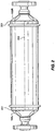
- FIG. 1 discloses a straight tube Coriolis flowmeter 5. Although shown in conjunction with a straight tube Coriolis flowmeter 5, those skilled in the art will recognize that this invention may also be used to house flow tubes having a curved or looped configuration.
- Coriolis flowmeter 5 is comprised of Coriolis sensor 10 and associated meter electronics 20.
- Coriolis sensor 10 has casing 103 which encloses flow tube 101 and surrounding balance bar 102.
- the flow tube 101 includes a left end portion thereof designated 101 L in a right end portion thereof designated 101 R.
- Flow tube 101 and its ends portions extend the entire length of the flowmeter from the input end 107 of flow tube 101 to the output end 108 of the flow tube.
- the balance bar 102 is connected at its ends to flow tube 101 by brace bar 121.
- Casing 103 has end portions 128 extending axially out from each end of the casing and connecting casing 103 to inlet flange 122 and outlet flange 122'.
- Inlet flange 122 and outlet flange 122' connect Coriolis sensor 10 to a pipeline.
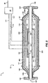
- a driver 104 and a left pick off 105 and a right pick off 105' are coupled to flow tube 101 and balance bar 102.
- Driver 104 receives signals over path 110 from meter electronics 20 to cause driver 104 to vibrate flow tube 101 and balance bar 102 in phase opposition at the resonant frequency of the material filled flow tube 101.
- the oscillation of vibrating flow tube 101 together with the material flow therein induces Coriolis deflections in the flow tube in a well known manner.
- These Coriolis deflections are detected by pick offs 105 and 105' with the outputs of these pick offs being transmitted over conductors 111 and 111' to meter electronics 20.
- the phase difference between the output signals of these pick offs represents information pertaining to the material flow within flow tube 101.
- the pick offs signals are received over conductors 111 and 111' by meter electronics 20 which in a well known manner processes these signals to generate output information that is applied to conductor 26 representing the various parameters of the material flow. These parameters may include density, viscosity, mass flow rate and other information regarding material flow.
- the present invention as described herein, can produce multiple drive signals for multiple drivers.
- Meter electronics 20 processes left and right velocity signals to compute mass flow rate.
- Path 26 provides an input and an output means that allows meter electronics 20 to interface with an operator. An explanation of the circuitry of meter electronics 20 is unneeded to understand the casing 103 and veneer 150 of the present invention and is omitted for brevity of this description.
- the present invention relates to casing 103 having a veneer 150 that encloses outer surface 151 of casing 103.
- casing 103 bears the structural load of casing and a separate veneer 150 provides a sanitary or corrosion proof surface for casing 103.
- Casing 103 is made of a first material. The first material is not sanitary and is not corrosion resistant.
- Veneer 150 is made of a second material that is dissimilar from the first material.
- dissimilar means that the two material have different properties, such as different coefficients of thermal expansion.
- the second material is a corrosion resistant material, and is stainless steel.
- Veneer 150 encloses the outer surface 151 and provides a sanitary and/or corrosive covering for sensor 10.
- veneer 150 is affixed to outer surface 151 of casing 103 ( FIG.1 ) in the following manner. Veneer 150 is affixed to ends 103L and 103R of casing 103 by orbital weld 201. Longitudinal weld 202 is used to seal overlapping sides of veneer 150 after veneer 150 is wrapped around casing 103.
- casing 103 is made of a material that has a coefficient of thermal expansion that is substantially equal to the material from which flow tube 101 is made.
- flow tube 101 may be made of titanium which has a coefficient of thermal expansion that is 4.6e -6 per 0.55 degrees Celsius and casing 103 is composed of carbon steel which has a coefficient of 6.5e -6 per 0.55 degrees Celsius which is since sufficiently equal for most operations.
- veneer 150 is made of stainless steel which has a coefficient of thermal expansion that is 4.6e -6 per 0.55 degrees Celsius, the disparity between the thermal coefficients for veneer 150 and flow tube 101 or casing 103 can be too great.
- veneer 150 is a separate structure having an inner surface and an outer surface. Veneer 150 may have ends that are affixed to a right end 103R of casing 103 and a left end 103L of casing 103.
- Gap 170 is formed between inner surface of veneer 150 and outer surface 151 of casing 103.
- the gap 170 allows casing 103 to expand and contract inside veneer 150 without applying any stress to veneer 150.
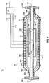
- veneer 150 may have bellows 191 (Shown on FIGS. 3-5 ) at opposing ends of casing 150. Bellows 191 are bends in the surface of veneer 150 that can expand and contract so that as the underlying casing 103 expands and contracts, bellows 191 bend and unbend to prevent stress on veneer 150.
- gap 170 may contain insulation 300 as shown in FIG. 3 .
- Insulation 300 keeps the temperature more uniform inside veneer 150.
- Insulation 300 may be used to retain heat in casing 103. This heat retention reduces axial stress due to temperature gradients inside Coriolis sensor 10.
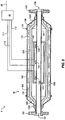
- Heating elements 400 (Shown in FIG. 4 ) may also be mounted inside gap 170. Heating elements 400 provide a heat jacket that heats casing 103 to reduce axial stress in Coriolis sensor 10 caused by expansion and contraction of flow tube 101.
- a fluid 500 (Shown by arrows in FIG. 5 ) may flow through gap 170 to regulate the temperature of Coriolis sensor 10.
Landscapes
- Physics & Mathematics (AREA)
- Fluid Mechanics (AREA)
- General Physics & Mathematics (AREA)
- Measuring Volume Flow (AREA)
Priority Applications (1)
| Application Number | Priority Date | Filing Date | Title |
|---|---|---|---|
| DE60028375.5T DE60028375T3 (de) | 1999-06-30 | 2000-06-12 | Coriolisdurchflussmesser mit einem gehäuse mit einer äusseren schutzhaut |
Applications Claiming Priority (3)
| Application Number | Priority Date | Filing Date | Title |
|---|---|---|---|
| US345085 | 1999-06-30 | ||
| US09/345,085 US6330832B1 (en) | 1999-06-30 | 1999-06-30 | Coriolis flowmeter having a casing enclosed in a veneer |
| PCT/US2000/016030 WO2001002812A1 (en) | 1999-06-30 | 2000-06-12 | Coriolis flowmeter having a casing with a protective outer layer |
Publications (3)
| Publication Number | Publication Date |
|---|---|
| EP1194747A1 EP1194747A1 (en) | 2002-04-10 |
| EP1194747B1 EP1194747B1 (en) | 2006-05-31 |
| EP1194747B2 true EP1194747B2 (en) | 2017-01-11 |
Family
ID=23353443
Family Applications (1)
| Application Number | Title | Priority Date | Filing Date |
|---|---|---|---|
| EP00941336.0A Expired - Lifetime EP1194747B2 (en) | 1999-06-30 | 2000-06-12 | Coriolis flowmeter having a casing with a protective outer layer |
Country Status (14)
| Country | Link |
|---|---|
| US (1) | US6330832B1 (enExample) |
| EP (1) | EP1194747B2 (enExample) |
| JP (1) | JP4426746B2 (enExample) |
| KR (1) | KR100505953B1 (enExample) |
| CN (1) | CN1162687C (enExample) |
| AR (1) | AR022052A1 (enExample) |
| AU (1) | AU5605200A (enExample) |
| BR (1) | BRPI0011911B1 (enExample) |
| CA (1) | CA2377870C (enExample) |
| DE (1) | DE60028375T3 (enExample) |
| HK (1) | HK1047617B (enExample) |
| MX (1) | MXPA01013251A (enExample) |
| RU (1) | RU2233433C2 (enExample) |
| WO (1) | WO2001002812A1 (enExample) |
Families Citing this family (37)
| Publication number | Priority date | Publication date | Assignee | Title |
|---|---|---|---|---|
| DE10017963C2 (de) * | 2000-04-12 | 2003-01-30 | Krohne Ag Basel | Massendurchflussmessgerät |
| US6651513B2 (en) * | 2000-04-27 | 2003-11-25 | Endress + Hauser Flowtec Ag | Vibration meter and method of measuring a viscosity of a fluid |
| DE10351311B3 (de) * | 2003-10-31 | 2005-06-30 | Abb Patent Gmbh | Coriolis-Massendurchflussmessgerät |
| DE102005001809A1 (de) * | 2005-01-13 | 2006-07-27 | Endress + Hauser Flowtec Ag | Verfahren zur Regelung eines thermischen bzw. kalorimetrischen Durchflussmessgeräts |
| US7451662B2 (en) * | 2005-02-25 | 2008-11-18 | Endress + Hauser Flowtec Ag | Vibration type measurement transducer |
| JP4668664B2 (ja) * | 2005-04-08 | 2011-04-13 | 株式会社オーバル | 多重管構造形直管式コリオリ流量計 |
| US7874220B2 (en) * | 2006-11-16 | 2011-01-25 | Abb Patent Gmbh | Coriolis mass flowmeter with an oscillatable straight measuring tube |
| DE102007062397A1 (de) * | 2007-12-20 | 2009-06-25 | Endress + Hauser Flowtec Ag | Meßwandler vom Vibrationstyp |
| DE102008035877A1 (de) | 2008-08-01 | 2010-02-04 | Endress + Hauser Flowtec Ag | Meßwandler vom Vibrationstyp |
| DE102008050113A1 (de) | 2008-10-06 | 2010-04-08 | Endress + Hauser Flowtec Ag | In-Line-Meßgerät |
| DE102008050115A1 (de) | 2008-10-06 | 2010-04-08 | Endress + Hauser Flowtec Ag | In-Line-Meßgerät |
| DE102008050116A1 (de) | 2008-10-06 | 2010-04-08 | Endress + Hauser Flowtec Ag | In-Line-Meßgerät |
| DE102008044186A1 (de) | 2008-11-28 | 2010-06-02 | Endress + Hauser Flowtec Ag | Magneteinrichtung sowie Meßaufnehmer vom Vibrationstyp mit einer solchen Magneteinrichtung |
| DE102009012474A1 (de) | 2009-03-12 | 2010-09-16 | Endress + Hauser Flowtec Ag | Meßsystem mit einem Messwandler vom Vibrationstyp |
| DE102009028006A1 (de) | 2009-07-24 | 2011-01-27 | Endress + Hauser Flowtec Ag | Meßwandler vom Vibrationstyp sowie Meßgerät mit einem solchen Meßwandler |
| DE102009028007A1 (de) | 2009-07-24 | 2011-01-27 | Endress + Hauser Flowtec Ag | Meßumwandler vom Vibrationstyp sowie Meßgerät mit einem solchen Meßwandler |
| RU2522184C2 (ru) | 2009-09-14 | 2014-07-10 | Майкро Моушн, Инк. | Коррозионно-стойкое покрытие для вибрационного расходомера и способ формирования этого покрытия |
| DE102010000760B4 (de) | 2010-01-11 | 2021-12-23 | Endress + Hauser Flowtec Ag | Meßsystem mit einem Meßwandler vom Vibrationstyp zum Messen eines statischen Drucks in einem strömenden Medium |
| WO2011080171A2 (de) | 2009-12-31 | 2011-07-07 | Endress+Hauser Flowtec Ag | MEßSYSTEM MIT EINEM MEßWANDLER VOM VIBRATIONSTYP |
| CA2785933C (en) | 2009-12-31 | 2016-05-24 | Endress+Hauser Flowtec Ag | Measuring system having a measuring transducer of vibration-type |
| DE102010000761A1 (de) | 2010-01-11 | 2011-07-28 | Endress + Hauser Flowtec Ag | Meßsystem mit einem Meßwandler vom Vibrationstyp |
| DE102010000759B4 (de) | 2010-01-11 | 2025-05-22 | Endress + Hauser Flowtec Ag | Meßsystem mit einem Meßwandler vom Vibrationstyp |
| EP2519806B1 (de) | 2009-12-31 | 2018-02-07 | Endress+Hauser Flowtec AG | Mess-system mit einem messwandler vom vibrationstyp |
| DE102010039543A1 (de) | 2010-08-19 | 2012-02-23 | Endress + Hauser Flowtec Ag | Meßsystem mit einem Meßwandler vom Vibrationstyp |
| DE102010044179A1 (de) | 2010-11-11 | 2012-05-16 | Endress + Hauser Flowtec Ag | Meßsystem mit einem Meßwandler von Vibrationstyp |
| CN103206998B (zh) * | 2012-01-13 | 2015-09-30 | 艾默生过程控制流量技术有限公司 | 内置伴热装置的流量计 |
| US9080908B2 (en) | 2013-07-24 | 2015-07-14 | Jesse Yoder | Flowmeter design for large diameter pipes |
| US8820175B1 (en) * | 2013-09-10 | 2014-09-02 | King Fahd University Of Petroleum And Minerals | Sensor for two-phase flow measurements |
| DE102018133117A1 (de) | 2018-12-20 | 2020-06-25 | Endress+Hauser Flowtec Ag | Coriolis-Massendurchfluß-Meßgerät |
| US12174212B2 (en) | 2018-12-20 | 2024-12-24 | Endress+Hauser Flowtec Ag | Coriolis mass flow meter |
| EP3899447B1 (de) | 2018-12-20 | 2023-09-20 | Endress + Hauser Flowtec AG | Coriolis-massendurchfluss-messgerät |
| WO2020126286A1 (de) | 2018-12-21 | 2020-06-25 | Endress+Hauser Flowtec Ag | CORIOLIS-MASSENDURCHFLUß-MEßGERÄT MIT MAGNETFELDDETEKTOR |
| DE102019133610A1 (de) | 2019-12-09 | 2021-06-10 | Endress + Hauser Flowtec Ag | Vibronisches Meßsystem zum Messen eines Massestroms eines fluiden Meßstoff |
| CN116157655A (zh) | 2020-06-18 | 2023-05-23 | 恩德斯+豪斯流量技术股份有限公司 | 电子振动测量系统 |
| DE102020131649A1 (de) | 2020-09-03 | 2022-03-03 | Endress + Hauser Flowtec Ag | Vibronisches Meßsystem |
| DE102020127382A1 (de) | 2020-10-16 | 2022-04-21 | Endress+Hauser Flowtec Ag | Verfahren zum Überprüfen eines vibronischen Meßsystems |
| KR102796227B1 (ko) * | 2023-03-27 | 2025-04-16 | 정우이앤이 주식회사 | 극저온용 코리올리스 유량계 |
Citations (1)
| Publication number | Priority date | Publication date | Assignee | Title |
|---|---|---|---|---|
| US4823614A (en) † | 1986-04-28 | 1989-04-25 | Dahlin Erik B | Coriolis-type mass flowmeter |
Family Cites Families (10)
| Publication number | Priority date | Publication date | Assignee | Title |
|---|---|---|---|---|
| FR2611267B1 (fr) * | 1987-02-20 | 1989-06-09 | Sgn Soc Gen Tech Nouvelle | Debitmetre pour liquides dangereux |
| DE4027936A1 (de) * | 1990-09-04 | 1992-03-05 | Rota Yokogawa Gmbh & Co Kg | Massedosierautomat |
| WO1992014123A1 (en) | 1991-02-05 | 1992-08-20 | Donald Reed Cage | Improved coriolis mass flow rate meter |
| EP0518124B1 (de) * | 1991-06-09 | 1995-09-06 | Krohne AG | Coriolis-Massendurchflussmessgerät |
| DE4124295A1 (de) * | 1991-07-22 | 1993-01-28 | Krohne Ag | Massendurchflussmessgeraet |
| US5347874A (en) * | 1993-01-25 | 1994-09-20 | Micro Motion, Incorporated | In-flow coriolis effect mass flowmeter |
| DE59510157D1 (de) * | 1995-06-14 | 2002-05-16 | Flowtec Ag | Coriolis-Massedurchflussaufnehmer mit einem einzigen Messrohr |
| DE19632500C2 (de) | 1996-08-12 | 1999-10-28 | Krohne Ag Basel | Massendurchflußmeßgerät |
| US5850039A (en) | 1997-02-27 | 1998-12-15 | Micro Motion | Coriolis flowmeter having axially compliant case ends |
| US6332367B1 (en) * | 1997-03-11 | 2001-12-25 | Micro Motion, Inc. | Dual loop Coriolis effect mass flowmeter |
-
1999
- 1999-06-30 US US09/345,085 patent/US6330832B1/en not_active Expired - Lifetime
-
2000
- 2000-06-12 RU RU2002102225/28A patent/RU2233433C2/ru active
- 2000-06-12 KR KR10-2001-7016911A patent/KR100505953B1/ko not_active Expired - Fee Related
- 2000-06-12 CN CNB008119805A patent/CN1162687C/zh not_active Expired - Lifetime
- 2000-06-12 HK HK02109213.0A patent/HK1047617B/zh not_active IP Right Cessation
- 2000-06-12 MX MXPA01013251A patent/MXPA01013251A/es active IP Right Grant
- 2000-06-12 JP JP2001508009A patent/JP4426746B2/ja not_active Expired - Fee Related
- 2000-06-12 CA CA002377870A patent/CA2377870C/en not_active Expired - Lifetime
- 2000-06-12 AU AU56052/00A patent/AU5605200A/en not_active Abandoned
- 2000-06-12 EP EP00941336.0A patent/EP1194747B2/en not_active Expired - Lifetime
- 2000-06-12 WO PCT/US2000/016030 patent/WO2001002812A1/en not_active Ceased
- 2000-06-12 DE DE60028375.5T patent/DE60028375T3/de not_active Expired - Lifetime
- 2000-06-12 BR BRPI0011911A patent/BRPI0011911B1/pt active IP Right Grant
- 2000-06-29 AR ARP000103308A patent/AR022052A1/es not_active Application Discontinuation
Patent Citations (1)
| Publication number | Priority date | Publication date | Assignee | Title |
|---|---|---|---|---|
| US4823614A (en) † | 1986-04-28 | 1989-04-25 | Dahlin Erik B | Coriolis-type mass flowmeter |
Non-Patent Citations (1)
| Title |
|---|
| "G+ Class Mass flowmeters for high and low flow rates of liquid products. Technical data. Corimass MFM 4085 K / MFM 4085 F", September 1997, KROHNE † |
Also Published As
| Publication number | Publication date |
|---|---|
| RU2233433C2 (ru) | 2004-07-27 |
| US6330832B1 (en) | 2001-12-18 |
| EP1194747A1 (en) | 2002-04-10 |
| DE60028375T3 (de) | 2017-06-01 |
| EP1194747B1 (en) | 2006-05-31 |
| WO2001002812A1 (en) | 2001-01-11 |
| CN1371469A (zh) | 2002-09-25 |
| BRPI0011911B1 (pt) | 2016-05-24 |
| CA2377870C (en) | 2005-01-04 |
| AR022052A1 (es) | 2002-09-04 |
| CN1162687C (zh) | 2004-08-18 |
| DE60028375D1 (de) | 2006-07-06 |
| DE60028375T2 (de) | 2006-11-02 |
| MXPA01013251A (es) | 2002-06-21 |
| KR20020019937A (ko) | 2002-03-13 |
| BR0011911A (pt) | 2002-03-19 |
| HK1047617A1 (en) | 2003-02-28 |
| JP2003503719A (ja) | 2003-01-28 |
| KR100505953B1 (ko) | 2005-08-05 |
| AU5605200A (en) | 2001-01-22 |
| JP4426746B2 (ja) | 2010-03-03 |
| HK1047617B (zh) | 2005-05-06 |
| CA2377870A1 (en) | 2001-01-11 |
Similar Documents
| Publication | Publication Date | Title |
|---|---|---|
| EP1194747B2 (en) | Coriolis flowmeter having a casing with a protective outer layer | |
| EP0757782B1 (en) | Coriolis mass flow rate meter | |
| RU2291401C2 (ru) | Измерительный вибрационный преобразователь, применение измерительного вибрационного преобразователя и способ уменьшения чувствительности к давлению измерительного вибрационного преобразователя | |
| CN103124897B (zh) | 包括改进仪表外壳的振动计 | |
| RU2581428C2 (ru) | Вибрационное устройство измерения параметров потока и способ для изготовления вибрационного устройства измерения параметров потока | |
| EP0985135B1 (en) | Coriolis flowmeter having corrugated flow tube | |
| RU2581436C2 (ru) | Компенсация тепловых напряжений в вибрационном расходомере с изогнутым трубопроводом | |
| AU767546B2 (en) | Apparatus for connecting a coriolis flowmeter to a case | |
| CN103124898B (zh) | 包括阻尼计量部件的振动计 | |
| CN100443862C (zh) | 科里奥利流量计 | |
| WO2013028200A1 (en) | Transmitter mount for a fluid flowmeter | |
| MXPA01008508A (en) | A low thermal stress case connect link for a straight tube coriolis flowmeter |
Legal Events
| Date | Code | Title | Description |
|---|---|---|---|
| PUAI | Public reference made under article 153(3) epc to a published international application that has entered the european phase |
Free format text: ORIGINAL CODE: 0009012 |
|
| 17P | Request for examination filed |
Effective date: 20020114 |
|
| AK | Designated contracting states |
Kind code of ref document: A1 Designated state(s): AT BE CH CY DE DK ES FI FR GB GR IE IT LI LU MC NL PT SE |
|
| RIN1 | Information on inventor provided before grant (corrected) |
Inventor name: OVERFELT, MICHAEL, LEON Inventor name: NORMEN, DAVID, F. |
|
| RBV | Designated contracting states (corrected) |
Designated state(s): CH DE FR GB LI |
|
| 17Q | First examination report despatched |
Effective date: 20040813 |
|
| GRAP | Despatch of communication of intention to grant a patent |
Free format text: ORIGINAL CODE: EPIDOSNIGR1 |
|
| GRAS | Grant fee paid |
Free format text: ORIGINAL CODE: EPIDOSNIGR3 |
|
| GRAA | (expected) grant |
Free format text: ORIGINAL CODE: 0009210 |
|
| AK | Designated contracting states |
Kind code of ref document: B1 Designated state(s): CH DE FR GB LI |
|
| REG | Reference to a national code |
Ref country code: CH Ref legal event code: NV Representative=s name: TROESCH SCHEIDEGGER WERNER AG Ref country code: GB Ref legal event code: FG4D Ref country code: CH Ref legal event code: EP |
|
| REF | Corresponds to: |
Ref document number: 60028375 Country of ref document: DE Date of ref document: 20060706 Kind code of ref document: P |
|
| ET | Fr: translation filed | ||
| PLBI | Opposition filed |
Free format text: ORIGINAL CODE: 0009260 |
|
| PLAX | Notice of opposition and request to file observation + time limit sent |
Free format text: ORIGINAL CODE: EPIDOSNOBS2 |
|
| 26 | Opposition filed |
Opponent name: KROHNE MESSTECHNIK GMBH & CO. KG Effective date: 20070223 |
|
| PLAF | Information modified related to communication of a notice of opposition and request to file observations + time limit |
Free format text: ORIGINAL CODE: EPIDOSCOBS2 |
|
| PLBB | Reply of patent proprietor to notice(s) of opposition received |
Free format text: ORIGINAL CODE: EPIDOSNOBS3 |
|
| PLAY | Examination report in opposition despatched + time limit |
Free format text: ORIGINAL CODE: EPIDOSNORE2 |
|
| PLAH | Information related to despatch of examination report in opposition + time limit modified |
Free format text: ORIGINAL CODE: EPIDOSCORE2 |
|
| PLBC | Reply to examination report in opposition received |
Free format text: ORIGINAL CODE: EPIDOSNORE3 |
|
| PLCK | Communication despatched that opposition was rejected |
Free format text: ORIGINAL CODE: EPIDOSNREJ1 |
|
| APBM | Appeal reference recorded |
Free format text: ORIGINAL CODE: EPIDOSNREFNO |
|
| APBP | Date of receipt of notice of appeal recorded |
Free format text: ORIGINAL CODE: EPIDOSNNOA2O |
|
| APAH | Appeal reference modified |
Free format text: ORIGINAL CODE: EPIDOSCREFNO |
|
| APBQ | Date of receipt of statement of grounds of appeal recorded |
Free format text: ORIGINAL CODE: EPIDOSNNOA3O |
|
| PLAB | Opposition data, opponent's data or that of the opponent's representative modified |
Free format text: ORIGINAL CODE: 0009299OPPO |
|
| R26 | Opposition filed (corrected) |
Opponent name: KROHNE MESSTECHNIK GMBH & CO. KG Effective date: 20070223 |
|
| REG | Reference to a national code |
Ref country code: FR Ref legal event code: PLFP Year of fee payment: 17 |
|
| REG | Reference to a national code |
Ref country code: DE Ref legal event code: R100 Ref document number: 60028375 Country of ref document: DE |
|
| APBU | Appeal procedure closed |
Free format text: ORIGINAL CODE: EPIDOSNNOA9O |
|
| PLBN | Opposition rejected |
Free format text: ORIGINAL CODE: 0009273 |
|
| 27O | Opposition rejected |
Effective date: 20160712 |
|
| PUAH | Patent maintained in amended form |
Free format text: ORIGINAL CODE: 0009272 |
|
| STAA | Information on the status of an ep patent application or granted ep patent |
Free format text: STATUS: PATENT MAINTAINED AS AMENDED |
|
| PLAE | Information related to rejection of opposition modified |
Free format text: ORIGINAL CODE: 0009299REJO |
|
| 27A | Patent maintained in amended form |
Effective date: 20170111 |
|
| AK | Designated contracting states |
Kind code of ref document: B2 Designated state(s): CH DE FR GB LI |
|
| REG | Reference to a national code |
Ref country code: DE Ref legal event code: R102 Ref document number: 60028375 Country of ref document: DE |
|
| REG | Reference to a national code |
Ref country code: CH Ref legal event code: AELC |
|
| D27O | Information related to the rejection of opposition deleted | ||
| REG | Reference to a national code |
Ref country code: DE Ref legal event code: R082 Ref document number: 60028375 Country of ref document: DE Representative=s name: VOSSIUS & PARTNER PATENTANWAELTE RECHTSANWAELT, DE |
|
| REG | Reference to a national code |
Ref country code: FR Ref legal event code: PLFP Year of fee payment: 18 |
|
| REG | Reference to a national code |
Ref country code: FR Ref legal event code: PLFP Year of fee payment: 19 |
|
| PGFP | Annual fee paid to national office [announced via postgrant information from national office to epo] |
Ref country code: FR Payment date: 20190625 Year of fee payment: 20 |
|
| PGFP | Annual fee paid to national office [announced via postgrant information from national office to epo] |
Ref country code: DE Payment date: 20190627 Year of fee payment: 20 Ref country code: GB Payment date: 20190627 Year of fee payment: 20 |
|
| PGFP | Annual fee paid to national office [announced via postgrant information from national office to epo] |
Ref country code: CH Payment date: 20190702 Year of fee payment: 20 |
|
| REG | Reference to a national code |
Ref country code: DE Ref legal event code: R071 Ref document number: 60028375 Country of ref document: DE |
|
| REG | Reference to a national code |
Ref country code: CH Ref legal event code: PL |
|
| REG | Reference to a national code |
Ref country code: GB Ref legal event code: PE20 Expiry date: 20200611 |
|
| PG25 | Lapsed in a contracting state [announced via postgrant information from national office to epo] |
Ref country code: GB Free format text: LAPSE BECAUSE OF EXPIRATION OF PROTECTION Effective date: 20200611 |