EP1194011A2 - Umrichterschaltung und Verfahren zum Betrieb einer solchen - Google Patents
Umrichterschaltung und Verfahren zum Betrieb einer solchen Download PDFInfo
- Publication number
- EP1194011A2 EP1194011A2 EP01122762A EP01122762A EP1194011A2 EP 1194011 A2 EP1194011 A2 EP 1194011A2 EP 01122762 A EP01122762 A EP 01122762A EP 01122762 A EP01122762 A EP 01122762A EP 1194011 A2 EP1194011 A2 EP 1194011A2
- Authority
- EP
- European Patent Office
- Prior art keywords
- assigned
- induction
- main
- converter circuit
- load
- Prior art date
- Legal status (The legal status is an assumption and is not a legal conclusion. Google has not performed a legal analysis and makes no representation as to the accuracy of the status listed.)
- Granted
Links
- 238000000034 method Methods 0.000 title claims description 7
- 230000001419 dependent effect Effects 0.000 claims abstract description 8
- 239000004065 semiconductor Substances 0.000 claims abstract description 7
- 230000006698 induction Effects 0.000 claims description 63
- 238000010411 cooking Methods 0.000 claims description 17
- 238000004804 winding Methods 0.000 claims description 16
- 239000004020 conductor Substances 0.000 claims description 2
- 230000001939 inductive effect Effects 0.000 description 10
- 239000003990 capacitor Substances 0.000 description 8
- 230000008901 benefit Effects 0.000 description 6
- 238000010438 heat treatment Methods 0.000 description 6
- 230000004913 activation Effects 0.000 description 5
- 238000011217 control strategy Methods 0.000 description 5
- 238000010586 diagram Methods 0.000 description 5
- 238000011017 operating method Methods 0.000 description 4
- 238000004519 manufacturing process Methods 0.000 description 3
- 238000006243 chemical reaction Methods 0.000 description 2
- 230000009467 reduction Effects 0.000 description 2
- 230000009471 action Effects 0.000 description 1
- 230000008859 change Effects 0.000 description 1
- 238000001816 cooling Methods 0.000 description 1
- 238000009826 distribution Methods 0.000 description 1
- 230000005294 ferromagnetic effect Effects 0.000 description 1
- 230000003993 interaction Effects 0.000 description 1
- 230000005415 magnetization Effects 0.000 description 1
- 239000000463 material Substances 0.000 description 1
- 230000010363 phase shift Effects 0.000 description 1
- 230000001629 suppression Effects 0.000 description 1
Images


Classifications
-
- H—ELECTRICITY
- H05—ELECTRIC TECHNIQUES NOT OTHERWISE PROVIDED FOR
- H05B—ELECTRIC HEATING; ELECTRIC LIGHT SOURCES NOT OTHERWISE PROVIDED FOR; CIRCUIT ARRANGEMENTS FOR ELECTRIC LIGHT SOURCES, IN GENERAL
- H05B6/00—Heating by electric, magnetic or electromagnetic fields
- H05B6/02—Induction heating
- H05B6/06—Control, e.g. of temperature, of power
- H05B6/062—Control, e.g. of temperature, of power for cooking plates or the like
- H05B6/065—Control, e.g. of temperature, of power for cooking plates or the like using coordinated control of multiple induction coils
-
- H—ELECTRICITY
- H02—GENERATION; CONVERSION OR DISTRIBUTION OF ELECTRIC POWER
- H02M—APPARATUS FOR CONVERSION BETWEEN AC AND AC, BETWEEN AC AND DC, OR BETWEEN DC AND DC, AND FOR USE WITH MAINS OR SIMILAR POWER SUPPLY SYSTEMS; CONVERSION OF DC OR AC INPUT POWER INTO SURGE OUTPUT POWER; CONTROL OR REGULATION THEREOF
- H02M7/00—Conversion of AC power input into DC power output; Conversion of DC power input into AC power output
- H02M7/42—Conversion of DC power input into AC power output without possibility of reversal
- H02M7/44—Conversion of DC power input into AC power output without possibility of reversal by static converters
- H02M7/48—Conversion of DC power input into AC power output without possibility of reversal by static converters using discharge tubes with control electrode or semiconductor devices with control electrode
- H02M7/53—Conversion of DC power input into AC power output without possibility of reversal by static converters using discharge tubes with control electrode or semiconductor devices with control electrode using devices of a triode or transistor type requiring continuous application of a control signal
- H02M7/537—Conversion of DC power input into AC power output without possibility of reversal by static converters using discharge tubes with control electrode or semiconductor devices with control electrode using devices of a triode or transistor type requiring continuous application of a control signal using semiconductor devices only, e.g. single switched pulse inverters
- H02M7/5387—Conversion of DC power input into AC power output without possibility of reversal by static converters using discharge tubes with control electrode or semiconductor devices with control electrode using devices of a triode or transistor type requiring continuous application of a control signal using semiconductor devices only, e.g. single switched pulse inverters in a bridge configuration
-
- H—ELECTRICITY
- H05—ELECTRIC TECHNIQUES NOT OTHERWISE PROVIDED FOR
- H05B—ELECTRIC HEATING; ELECTRIC LIGHT SOURCES NOT OTHERWISE PROVIDED FOR; CIRCUIT ARRANGEMENTS FOR ELECTRIC LIGHT SOURCES, IN GENERAL
- H05B6/00—Heating by electric, magnetic or electromagnetic fields
- H05B6/02—Induction heating
- H05B6/04—Sources of current
Definitions
- the invention relates to a converter or inverter circuit, in particular for an induction hob, according to the preamble of claim 1 and an operating method for such.
- induction heating hobs hereinafter referred to as induction hobs with an induction coil arranged in the hotplate or cooking surface operated in a container containing the food, which is a ferromagnetic Has material that generates induction currents. Through the action of induction currents and The magnetization in the wall of the cooking vessel becomes the container and thus the food is heated.
- Such hobs have a much higher efficiency than other electrically operated hotplates, remain "cold” and put in operation lower demands on the flatness of the pot base.
- the energy supply for induction cookers is usually from a power source, which have an alternating current with an amplitude (peak-peak) of approx. 18 to 45 A. and provides a frequency between 25 and 40 kHz, and the performance of a single Cooking range is between 300 W and 3 kW.
- Most industrialized countries available induction cookers have between two and four induction hobs, which can also be combined with conventional hotplates. With modern devices In this way, individual or all hotplates comprise two concentrically to one another spirally wound inductors, of which the outer one can be optionally switched on is.
- the comparatively high-frequency operating currents are provided through inverter circuits (converters).
- EP 0 286 044 A2 describes a circuit for the power supply of an inductive hotplate that switches the power source on two hotplates while avoiding annoying noise from two over implemented a microprocessor controlled relay. Avoiding switching noises is here by switching the hot plates in the vicinity of the zero crossing of the mains voltage, for which the microprocessor has a corresponding Receives information from the power source.
- EP 0 583 519 A1 describes an induction cooking device with two induction coils, the a half-bridge converter is assigned to which they alternate via a relay can be connected.
- DE 196 54 268 C2 describes a further development of this Arrangement described with which a more compact control circuit is provided should.
- the cooking device has a rectifier and a converter circuit with at least three to the rectifier connected and connected in series power transistors, each of which Anti-parallel diode and an auxiliary resonance capacitor are connected in parallel.
- a main resonance capacitor is assigned to each induction heating coil and auxiliary diodes, each between an input of a main resonance capacitor and a rectifier output, such that when operating one induction heating coil the other is not powered.
- EP 0 724 379 describes a control device for induction hotplates with several heating elements described, the plurality of inductors connectable in parallel exhibit.
- This control unit has four outputs and enables differentiated Way separate controls and interconnection of several induction coils.
- the converter circuit essentially comprises two electronic RF switches, up to four inductive loads, one resonant circuit capacitor bank and up to four single-pole changeover switches.
- EP 0 986 287 A2 describes an inverter circuit with two outputs and one Procedure for controlling the power fed into their outputs described with which either a load or two loads at the same time (especially induction heating coils from inductive hotplates). With the one suggested there The converter circuit and the associated control method are used for dimensioning the switch and power semiconductor components as well as the control of the power supply of the induction coils can be optimized and noise can be minimized.
- the inverter proposed there is of the asymmetrical, three-phase H-bridge type with a common branch and two independent branches, the power components include. It has two switches that change the topology for optional control of one of the two induction coils or both at the same time. Capacitors are connected in series between each coil and the common branch to reduce the average current flow through the power semiconductor components (Transistors) provided.
- EP 0 971 562 A1 discloses a multi-coil arrangement for induction hotplates, which is the manufacture of home and professional cooking appliances Use with identical induction coils and converter or converter circuits allowed.
- the invention is therefore based on the object of a further improved converter circuit of the generic type and an efficient operating method for such specify with which the effort to implement a flexible control of several Loads (hotplates or induction coils) are further reduced and their operation is even more efficient and can be made more user-friendly.
- Loads hotplates or induction coils
- This task is accomplished in terms of its device aspect by a converter circuit with the features of claim 1 and with regard to their procedural aspect solved by an operating method with the features of claim 9.
- the invention includes the essential idea of one partial duplication of a conventional inverter topology to form a topology with multiple outputs. Those are duplicated or multiplied Sections of the known topology that allow independent control of the outputs. Performing this partial duplication requires identification of the Sections of the original topology necessary to control the output.
- the Topology created by this procedure can be implemented by introducing additional switches (Commutators) can be optimized by using the inactive outputs Active outputs can be reconfigured. This enables an increase the conversion or conversion efficiency and a (further) reduction the operating temperature of the power components in the sense of the above Task.
- the invention further includes the idea of using and modifying one Inverter structure of the bridge or half-bridge type to form an inverter topology with multiple outputs.
- Inverter structure of the bridge or half-bridge type to form an inverter topology with multiple outputs.
- inverter circuits with multiple outputs can be used - for example of electric motors with several windings or main and auxiliary windings, Transformer arrangements with multiple windings and / or main and auxiliary windings as well as lighting arrangements.
- the invention includes the idea provide a control strategy with the same frequency for all outputs of the converter.
- a suitable tax strategy should reduce losses across the board Performance range and thus the requirements for cooling and / or component specifications while maintaining the proposed configuration Bring advantages.
- This strategy - explained in more detail below - can be described as a single-pole Voltage suppression or cancellation are called.
- the proposed and claimed converter circuit is based on a series resonance bridge circuit with two independent outputs, as described in EP 0 986 287 A2 is described in a similar form.
- every exit to connect to a (inductive) load is assigned a series capacity.
- the bridge branches are each High-frequency electronic switches arranged, which are costly power semiconductor devices include.
- a special case of the converter circuit according to the invention which is particularly important for induction cooking appliances is one with two outputs, which has two single-pole changeover switches optionally with one of two electronic high-frequency switches or both high-frequency switches are connectable. Since induction cooking devices usually have two or four inductive hotplates are equipped, allow one or two such converter circuits the supply of an induction cooker with the need high-frequency AC.
- the high-frequency switches each have - in a manner known per se - a parallel connection from a power transistor and a diode, and the switch can be designed in a proven manner as an electromechanical relay. Furthermore, the Circuit an inductive and a capacitive input filter. With this proven component constellation the converter circuit achieves high reliability and a long service life at low manufacturing costs.
- the converter circuit in an induction cooker with at least two independently controllable main induction coils as loads and one auxiliary induction coil assigned to each used as additional loads.
- the invention can also be used for induction cooking devices can be realized with four inductive hotplates, two of which or all have four additional auxiliary inductors.
- the main induction coils and auxiliary induction coils as concentrically spiraling in one Level wound conductor.
- the auxiliary induction coils are essentially for half the power consumption designed as the main induction coils.
- the invention can in principle also be used for electric motors with two or more independently controllable main motor windings as loads and one auxiliary motor winding assigned to each main motor winding as an additional load or on transformer arrangements with two or more independently controllable Main windings as loads and one each assigned to each main winding Auxiliary winding as an additional load.
- Fig. 1 is an inverter circuit for the power supply of two induction hobs one main induction coil F1, F2 and one auxiliary induction coil F1aux, F2aux shown in FIG. 2.
- the inverter or converter circuit comprises one DC voltage source VS, an inductive input filter LF, a capacitive input filter CF and six electronic RF switches SW1 to SW6 in an H-type bridge circuit and a capacitor bank in series with each of the loads F1, F2, F1aux and F2aux C1, C2, C1aux and C2aux.
- the main and auxiliary inductors are switched by switches (electromechanical relays) R1, R2, R1aux and R2aux in the manner shown in the figure with nodes connected between the switches SW3 and SW4 or SW5 and SW6. That of the respective Connections of the capacitor banks C1, C2, C1aux facing away from inductance and C2aux are with nodes between the RF switches SW1 and SW2 and SW6 and SW4 or SW6 and the negative pole of the voltage source VS connected. All in all is the inverter circuit of the three-legged series resonance type and by the changeover switch so configurable that the electronic RF switches that are used for an inactive induction coil not needed to contribute to the supply of one of the active induction coils.
- the switches SW1, SW2 are alternately switched on and off at a fixed frequency, and the switches SW3, SW4, SW5 and SW6 are with a duty cycle on and off, which is proportional to the desired output power to the Outputs (main induction coils) F1 and F2 is.
- the switch R1, R2 the inverter circuit can handle both loads (main induction coils) or only supply one of the two.
- the parallel availability of the RF switches SW3, SW5 and SW4, SW6 increases the maximum supplied to the respective output Performance and increases energy efficiency, reducing the working temperature of the RF switch can be reduced if only one of the outputs (one of the inductive hotplates) is used.
- the Activation state of switch R1aux decided. If it is determined that a sufficient cooking appliance is on the hotplate, R1aux is switched on and thereby supplies the auxiliary induction coil F1aux with a current which the main inductor F1 flowing current is proportional to the duty cycle is the same. The same applies to the interaction of F2, R2aux and F2aux. is a small pot on one of the hotplates - such as F1 - which in turn is detected of the current flowing there is determined, the associated main switch (for F1 so R1) switched off, and only the main induction coil (inner coil) operated.
- the output powers of the main induction coils F1, F2 are 800 W, for example and 1400 W and those of the auxiliary inductors F1aux and F2aux, for example 400 W and 700 W.
- FIG. 4 shows the voltage waveform v o and the current waveform shape i L as a function of time over an RLC load during a switching cycle T according to a preferred control strategy for the proposed converter circuit.
- D is the duty cycle and ⁇ + the phase angle in the positive half period and ⁇ - the phase angle in the negative half period.
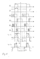
- FIG. 5 shows, in a corresponding timing diagram, the activation signals for six electronic switches (power semiconductor components) Q 1 to Q 42 of a two-output bridge topology which is controlled in accordance with this control strategy.
- the voltages are denoted by v o1 , v o2 and the currents across the loads by i L1 and i L2, respectively, and ⁇ 1+ , ⁇ 2+ again denote the phase angles in the positive half-wave and ⁇ 1- or ⁇ 2- die Phase angle in the negative half wave.
- the switching devices (RF switches) of the topology can be of the ZVS or ZCS switching type, depending on the specific values of D, ⁇ + , ⁇ - , m and Q.
- FIG. 6 shows a timing diagram in a schematic illustration based on FIG. 5 the activation signals for the special case of so-called single-pole voltage cancellation for the elementary case of a single load and four switching devices and the associated voltage and current waveform.
Landscapes
- Physics & Mathematics (AREA)
- Electromagnetism (AREA)
- Engineering & Computer Science (AREA)
- Power Engineering (AREA)
- Inverter Devices (AREA)
- Induction Heating Cooking Devices (AREA)
- Ac-Ac Conversion (AREA)
- Dc-Dc Converters (AREA)
- Input Circuits Of Receivers And Coupling Of Receivers And Audio Equipment (AREA)
Abstract
Description
Claims (9)
- Umrichterschaltung vom Serienresonanz-Brückentyp mit mindestens zwei unabhängigen Ausgängen zur Verbindung mit je einer Last (F1, F2), denen je eine Serienkapazität zugeordnet ist,
mit einer Gleichspannungsquelle (VS), einer unsymmetrischen Brückenschaltung aus einem gemeinsamen Zweig und voneinander unabhängigen Zweigen, welche jeweils elektronische Hochfrequenzschalter (SW1...SW6) mit Leistungs-Halbleiterbauelementen umfassen, und Umschaltern (R1, R2) zur Veränderung der Topologie zur wählbaren Speisung einer Last an einem ausgewählten Ausgang oder mehrerer Lasten an mehreren Ausgängen,
gekennzeichnet durch
je einen jedem unabhängigen Ausgang zugeordneten abhängigen Ausgang zur Verbindung mit einer Zusatzlast (F1aux, F2aux),
je einem jedem abhängigen Ausgang zugeordneten Umschalter (R1aux, R2aux) und
je eine jeder Zusatzlast zugeordnete Serienkapazität (C1aux, C2aux). - Umrichterschaltung nach Anspruch 1,
gekennzeichnet durch
zwei unabhängige und zwei abhängige Ausgänge, denen je ein einpoliger Umschalter (R1, R1aux, R2, R2aux) zugeordnet ist, und sechs elektronische Hochfrequenzschalter (SW1...SW6). - Umrichterschaltung nach Anspruch 1 oder 2,
dadurch gekennzeichnet, daß
die elektronischen Hochfrequenzschalter (SW1...SW6) jeweils einen Transistor und eine zu diesem antiparallel geschaltete Diode aufweisen und die Umschalter als elektromechanische Relais ausgebildet sind. - Induktionskochgerät mit einer Umrichterschaltung nach einem der Ansprüche 1 bis 3 und mindestens zwei unabhängigen steuerbaren Haupt-Induktionsspulen (F1, F2) als Lasten sowie je einer jeder Haupt-Induktionsspule zugeordneten Hilfs-Induktionsspule (F1aux, F2aux) als Zusatzlast.
- Induktionskochgerät nach Anspruch 4,
dadurch gekennzeichnet, daß
die Haupt-Induktionsspulen (F1, F2) und Hilfs-Induktionsspulen (F1aux, F2aux) als zueinander konzentrisch spiralig in einer Ebene gewickelte Leiter ausgebildet sind. - Induktionskochgerät nach Anspruch 4 oder 5,
dadurch gekennzeichnet, daß
die Hilfs-Induktionsspulen (F1aux, F2aux) für im wesentlichen die halbe Leistungsaufnahme der Haupt-Induktionsspulen (F1, F2) ausgelegt sind. - Elektromotor mit einer Umrichterschaltung nach einem der Ansprüche 1 bis 3 und zwei oder mehr unabhängig steuerbaren Haupt-Motorwicklungen als Lasten sowie je einer jeder Haupt-Motorwicklung zugeordneten Hilfs-Motorwicklung als Zusatzlast.
- Transformatoranordnung mit einer Umrichterschaltung nach einem der Ansprüche 1 bis 3 und zwei oder mehr unabhängig steuerbaren Hauptwicklungen als Lasten sowie je einer jeder Hauptwicklung zugeordneten Hilfswicklung als Zusatzlast.
- Verfahren zum Betrieb einer Umrichterschaltung nach einem der Ansprüche 1 bis 3,
dadurch gekennzeichnet, daß
alle Ausgänge des Umrichters mit der gleichen Frequenz versorgt werden und das Prinzip der einpoligen Spannungsaufhebung angewandt wird.
Applications Claiming Priority (2)
| Application Number | Priority Date | Filing Date | Title |
|---|---|---|---|
| ES200002440 | 2000-09-29 | ||
| ES200002440 | 2000-09-29 |
Publications (3)
| Publication Number | Publication Date |
|---|---|
| EP1194011A2 true EP1194011A2 (de) | 2002-04-03 |
| EP1194011A3 EP1194011A3 (de) | 2005-12-28 |
| EP1194011B1 EP1194011B1 (de) | 2008-09-10 |
Family
ID=8495216
Family Applications (4)
| Application Number | Title | Priority Date | Filing Date |
|---|---|---|---|
| EP01122760A Withdrawn EP1194009A2 (de) | 2000-09-29 | 2001-09-21 | Umrichterschaltung und Verfahren zum Betrieb einer solchen |
| EP01122761A Withdrawn EP1194010A2 (de) | 2000-09-29 | 2001-09-21 | Umrichterschaltung und Verfahren zum Betrieb einer solchen |
| EP01122762A Expired - Lifetime EP1194011B1 (de) | 2000-09-29 | 2001-09-21 | Umrichterschaltung und Verfahren zum Betrieb einer solchen |
| EP01122759A Expired - Lifetime EP1194008B1 (de) | 2000-09-29 | 2001-09-21 | Umrichterschaltung und Verfahren zum Betrieb einer solchen |
Family Applications Before (2)
| Application Number | Title | Priority Date | Filing Date |
|---|---|---|---|
| EP01122760A Withdrawn EP1194009A2 (de) | 2000-09-29 | 2001-09-21 | Umrichterschaltung und Verfahren zum Betrieb einer solchen |
| EP01122761A Withdrawn EP1194010A2 (de) | 2000-09-29 | 2001-09-21 | Umrichterschaltung und Verfahren zum Betrieb einer solchen |
Family Applications After (1)
| Application Number | Title | Priority Date | Filing Date |
|---|---|---|---|
| EP01122759A Expired - Lifetime EP1194008B1 (de) | 2000-09-29 | 2001-09-21 | Umrichterschaltung und Verfahren zum Betrieb einer solchen |
Country Status (4)
| Country | Link |
|---|---|
| EP (4) | EP1194009A2 (de) |
| AT (2) | ATE456185T1 (de) |
| DE (2) | DE50114298D1 (de) |
| ES (1) | ES2338863T3 (de) |
Families Citing this family (8)
| Publication number | Priority date | Publication date | Assignee | Title |
|---|---|---|---|---|
| ES2237342B1 (es) * | 2005-02-08 | 2007-07-16 | Bsh Electrodomesticos España, S.A. | Dispositivo para calentamiento inductivo de un elemento calentador ferromagnetico y un elemento calentador no -ferromagnetico. |
| ES2300168B1 (es) * | 2005-10-27 | 2009-05-08 | Bsh Electrodomesticos España, S.A. | Encimera de cocina y procedimiento para el funcionamiento de una encimera de cocina. |
| DE102008015036A1 (de) | 2008-03-14 | 2009-09-17 | E.G.O. Elektro-Gerätebau GmbH | Vorrichtung und Verfahren zur Ansteuerung von Induktionsheizeinrichtungen eines Induktionskochfeldes |
| ES2385091B1 (es) * | 2010-04-27 | 2013-05-28 | Bsh Electrodomésticos España, S.A. | Dispositivo de encimera de cocción. |
| US9282593B2 (en) | 2011-06-03 | 2016-03-08 | General Electric Company | Device and system for induction heating |
| CN103596307B (zh) * | 2013-11-05 | 2015-10-14 | 美的集团股份有限公司 | 谐振控制电路和电磁加热装置 |
| US10075055B2 (en) | 2015-09-30 | 2018-09-11 | Apple Inc. | Zero-voltage-switching scheme for phase shift converters |
| ES2633492B1 (es) * | 2016-03-21 | 2018-07-04 | Bsh Electrodomésticos España, S.A. | Dispositivo de aparato de cocción |
Family Cites Families (4)
| Publication number | Priority date | Publication date | Assignee | Title |
|---|---|---|---|---|
| ES2128958B1 (es) * | 1996-11-21 | 2000-01-16 | Balay Sa | Procedimiento de control de potencia en cocinas de induccion alimentadas mediante inversores multipuente reconfigurables. |
| JP2001509634A (ja) * | 1997-07-09 | 2001-07-24 | アドバンスト・エナジー・インダストリーズ・インコーポレイテッド | 周波数選択型可変出力誘導ヒータシステムおよび方法 |
| FR2773014B1 (fr) * | 1997-12-23 | 2000-03-03 | Europ Equip Menager | Dispositif d'alimentation de plusieurs circuits resonants par un generateur de puissance a onduleur |
| ES2143430B1 (es) * | 1998-09-08 | 2000-12-16 | Balay Sa | Circuito inversor de dos salidas, y circuito y procedimiento de control de la potencia entregada en las salidas del inversor. |
-
2001
- 2001-09-21 ES ES01122759T patent/ES2338863T3/es not_active Expired - Lifetime
- 2001-09-21 DE DE50114298T patent/DE50114298D1/de not_active Expired - Lifetime
- 2001-09-21 EP EP01122760A patent/EP1194009A2/de not_active Withdrawn
- 2001-09-21 AT AT01122759T patent/ATE456185T1/de not_active IP Right Cessation
- 2001-09-21 EP EP01122761A patent/EP1194010A2/de not_active Withdrawn
- 2001-09-21 EP EP01122762A patent/EP1194011B1/de not_active Expired - Lifetime
- 2001-09-21 EP EP01122759A patent/EP1194008B1/de not_active Expired - Lifetime
- 2001-09-21 DE DE50115320T patent/DE50115320D1/de not_active Expired - Lifetime
- 2001-09-21 AT AT01122762T patent/ATE408261T1/de not_active IP Right Cessation
Also Published As
| Publication number | Publication date |
|---|---|
| EP1194011B1 (de) | 2008-09-10 |
| EP1194009A2 (de) | 2002-04-03 |
| EP1194010A2 (de) | 2002-04-03 |
| EP1194011A3 (de) | 2005-12-28 |
| DE50115320D1 (de) | 2010-03-11 |
| DE50114298D1 (de) | 2008-10-23 |
| EP1194008B1 (de) | 2010-01-20 |
| ATE408261T1 (de) | 2008-09-15 |
| ATE456185T1 (de) | 2010-02-15 |
| ES2338863T3 (es) | 2010-05-13 |
| EP1194008A2 (de) | 2002-04-03 |
| EP1194008A3 (de) | 2005-12-28 |
Similar Documents
| Publication | Publication Date | Title |
|---|---|---|
| DE69836312T2 (de) | Gerät zur Versorgung einer Vielzahl von Schwingkreisen durch einen Wechselrichter-Stromgenerator | |
| EP2494846B1 (de) | Kochfeld mit wenigstens zwei heizelementen und einer leistungselektronikanordnung | |
| DE69308746T2 (de) | Konfigurierbarer wechselrichter für 120 v oder240 v ausgangsspannung | |
| WO1998016994A1 (de) | Wechselrichter | |
| EP2384083A1 (de) | Schaltungsanordnung für ein Induktionskochgerät, Verfahren zum Betreiben der Schaltungsanordnung und Induktionskochgerät | |
| DE102012220324B4 (de) | Induktionsheizvorrichtung | |
| DE102009054582A1 (de) | Kochfeld mit einer Mehrzahl von Heizelementen | |
| EP1194011B1 (de) | Umrichterschaltung und Verfahren zum Betrieb einer solchen | |
| EP2497332B1 (de) | Kochfeld mit wenigstens zwei heizinduktoren | |
| EP2590476B1 (de) | Hausgerätevorrichtung | |
| EP3556181A1 (de) | Haushaltsgerätevorrichtung | |
| DE10238606A1 (de) | Schaltnetzteil | |
| EP4098078A1 (de) | Induktionsgargerätevorrichtung | |
| EP2515608B1 (de) | Hausgerätevorrichtung | |
| EP2774456B1 (de) | Induktionsheizvorrichtung | |
| EP2506670B1 (de) | Induktionsheizvorrichtung | |
| EP1266545B1 (de) | Elektronischer transformator | |
| EP2605361B1 (de) | Anordnung und Verfahren zum Betreiben einer Anordnung zur induktiven Energieübertragung an einen elektrischen Verbraucher | |
| EP2706817B1 (de) | Kochfeldvorrichtung | |
| DE69325354T2 (de) | Verfahren zur Speisung einer induktiven Last und Vorrichtung zur Durchführung dieses Verfahrens | |
| DE29515355U1 (de) | Gerät zur Steuerung der Heizelementen zugeführten Leistung | |
| EP4518136A1 (de) | Resonanter dc-steller und verfahren zum betreiben eines resonanten dc-stellers | |
| EP2692203B1 (de) | Induktionsheizvorrichtung | |
| DE3443809A1 (de) | Zweiquadrantenstromrichter | |
| EP2692205A1 (de) | Induktionsheizvorrichtung |
Legal Events
| Date | Code | Title | Description |
|---|---|---|---|
| PUAI | Public reference made under article 153(3) epc to a published international application that has entered the european phase |
Free format text: ORIGINAL CODE: 0009012 |
|
| AK | Designated contracting states |
Kind code of ref document: A2 Designated state(s): AT BE CH CY DE DK ES FI FR GB GR IE IT LI LU MC NL PT SE TR |
|
| AX | Request for extension of the european patent |
Free format text: AL;LT;LV;MK;RO;SI |
|
| PUAL | Search report despatched |
Free format text: ORIGINAL CODE: 0009013 |
|
| AK | Designated contracting states |
Kind code of ref document: A3 Designated state(s): AT BE CH CY DE DK ES FI FR GB GR IE IT LI LU MC NL PT SE TR |
|
| AX | Request for extension of the european patent |
Extension state: AL LT LV MK RO SI |
|
| RIC1 | Information provided on ipc code assigned before grant |
Ipc: 7H 05B 6/04 B Ipc: 7H 02M 7/5387 A Ipc: 7H 05B 6/06 B Ipc: 7H 05B 6/44 B |
|
| RAP1 | Party data changed (applicant data changed or rights of an application transferred) |
Owner name: BSH BOSCH UND SIEMENS HAUSGERAETE GMBH |
|
| 17P | Request for examination filed |
Effective date: 20060628 |
|
| 17Q | First examination report despatched |
Effective date: 20060801 |
|
| AKX | Designation fees paid |
Designated state(s): AT BE CH CY DE DK ES FI FR GB GR IE IT LI LU MC NL PT SE TR |
|
| GRAP | Despatch of communication of intention to grant a patent |
Free format text: ORIGINAL CODE: EPIDOSNIGR1 |
|
| RIN1 | Information on inventor provided before grant (corrected) |
Inventor name: BURDIO, JOSE MIGUEL Inventor name: HERNANDEZ BLASCO, PABLO JESUS Inventor name: MONTERDE AZNAR, FERNANDO Inventor name: GARCIA JIMENEZ, JOSE RAMON |
|
| RTI1 | Title (correction) |
Free format text: INVERTER CIRCUIT AND ITS METHOD OF CONTROLLING |
|
| GRAS | Grant fee paid |
Free format text: ORIGINAL CODE: EPIDOSNIGR3 |
|
| GRAA | (expected) grant |
Free format text: ORIGINAL CODE: 0009210 |
|
| AK | Designated contracting states |
Kind code of ref document: B1 Designated state(s): AT BE CH CY DE DK ES FI FR GB GR IE IT LI LU MC NL PT SE TR |
|
| REG | Reference to a national code |
Ref country code: GB Ref legal event code: FG4D Free format text: NOT ENGLISH |
|
| REG | Reference to a national code |
Ref country code: CH Ref legal event code: EP |
|
| REG | Reference to a national code |
Ref country code: IE Ref legal event code: FG4D Free format text: LANGUAGE OF EP DOCUMENT: GERMAN |
|
| REF | Corresponds to: |
Ref document number: 50114298 Country of ref document: DE Date of ref document: 20081023 Kind code of ref document: P |
|
| PG25 | Lapsed in a contracting state [announced via postgrant information from national office to epo] |
Ref country code: FI Free format text: LAPSE BECAUSE OF FAILURE TO SUBMIT A TRANSLATION OF THE DESCRIPTION OR TO PAY THE FEE WITHIN THE PRESCRIBED TIME-LIMIT Effective date: 20080910 |
|
| NLV1 | Nl: lapsed or annulled due to failure to fulfill the requirements of art. 29p and 29m of the patents act | ||
| BERE | Be: lapsed |
Owner name: BSH BOSCH UND SIEMENS HAUSGERATE G.M.B.H. Effective date: 20080930 |
|
| REG | Reference to a national code |
Ref country code: IE Ref legal event code: FD4D |
|
| PG25 | Lapsed in a contracting state [announced via postgrant information from national office to epo] |
Ref country code: ES Free format text: LAPSE BECAUSE OF FAILURE TO SUBMIT A TRANSLATION OF THE DESCRIPTION OR TO PAY THE FEE WITHIN THE PRESCRIBED TIME-LIMIT Effective date: 20081221 Ref country code: MC Free format text: LAPSE BECAUSE OF NON-PAYMENT OF DUE FEES Effective date: 20080930 Ref country code: IE Free format text: LAPSE BECAUSE OF FAILURE TO SUBMIT A TRANSLATION OF THE DESCRIPTION OR TO PAY THE FEE WITHIN THE PRESCRIBED TIME-LIMIT Effective date: 20080910 |
|
| REG | Reference to a national code |
Ref country code: CH Ref legal event code: PL |
|
| PG25 | Lapsed in a contracting state [announced via postgrant information from national office to epo] |
Ref country code: NL Free format text: LAPSE BECAUSE OF FAILURE TO SUBMIT A TRANSLATION OF THE DESCRIPTION OR TO PAY THE FEE WITHIN THE PRESCRIBED TIME-LIMIT Effective date: 20080910 Ref country code: PT Free format text: LAPSE BECAUSE OF FAILURE TO SUBMIT A TRANSLATION OF THE DESCRIPTION OR TO PAY THE FEE WITHIN THE PRESCRIBED TIME-LIMIT Effective date: 20090210 |
|
| PLBE | No opposition filed within time limit |
Free format text: ORIGINAL CODE: 0009261 |
|
| STAA | Information on the status of an ep patent application or granted ep patent |
Free format text: STATUS: NO OPPOSITION FILED WITHIN TIME LIMIT |
|
| PG25 | Lapsed in a contracting state [announced via postgrant information from national office to epo] |
Ref country code: BE Free format text: LAPSE BECAUSE OF NON-PAYMENT OF DUE FEES Effective date: 20080930 Ref country code: DK Free format text: LAPSE BECAUSE OF FAILURE TO SUBMIT A TRANSLATION OF THE DESCRIPTION OR TO PAY THE FEE WITHIN THE PRESCRIBED TIME-LIMIT Effective date: 20080910 |
|
| 26N | No opposition filed |
Effective date: 20090611 |
|
| GBPC | Gb: european patent ceased through non-payment of renewal fee |
Effective date: 20081210 |
|
| PG25 | Lapsed in a contracting state [announced via postgrant information from national office to epo] |
Ref country code: IT Free format text: LAPSE BECAUSE OF FAILURE TO SUBMIT A TRANSLATION OF THE DESCRIPTION OR TO PAY THE FEE WITHIN THE PRESCRIBED TIME-LIMIT Effective date: 20080910 |
|
| REG | Reference to a national code |
Ref country code: FR Ref legal event code: ST Effective date: 20090731 |
|
| PG25 | Lapsed in a contracting state [announced via postgrant information from national office to epo] |
Ref country code: CH Free format text: LAPSE BECAUSE OF NON-PAYMENT OF DUE FEES Effective date: 20080930 Ref country code: AT Free format text: LAPSE BECAUSE OF NON-PAYMENT OF DUE FEES Effective date: 20080921 Ref country code: LI Free format text: LAPSE BECAUSE OF NON-PAYMENT OF DUE FEES Effective date: 20080930 |
|
| PG25 | Lapsed in a contracting state [announced via postgrant information from national office to epo] |
Ref country code: GB Free format text: LAPSE BECAUSE OF NON-PAYMENT OF DUE FEES Effective date: 20081210 |
|
| PG25 | Lapsed in a contracting state [announced via postgrant information from national office to epo] |
Ref country code: SE Free format text: LAPSE BECAUSE OF FAILURE TO SUBMIT A TRANSLATION OF THE DESCRIPTION OR TO PAY THE FEE WITHIN THE PRESCRIBED TIME-LIMIT Effective date: 20081210 |
|
| PG25 | Lapsed in a contracting state [announced via postgrant information from national office to epo] |
Ref country code: CY Free format text: LAPSE BECAUSE OF FAILURE TO SUBMIT A TRANSLATION OF THE DESCRIPTION OR TO PAY THE FEE WITHIN THE PRESCRIBED TIME-LIMIT Effective date: 20080910 Ref country code: LU Free format text: LAPSE BECAUSE OF NON-PAYMENT OF DUE FEES Effective date: 20080921 |
|
| PG25 | Lapsed in a contracting state [announced via postgrant information from national office to epo] |
Ref country code: TR Free format text: LAPSE BECAUSE OF FAILURE TO SUBMIT A TRANSLATION OF THE DESCRIPTION OR TO PAY THE FEE WITHIN THE PRESCRIBED TIME-LIMIT Effective date: 20080910 |
|
| PG25 | Lapsed in a contracting state [announced via postgrant information from national office to epo] |
Ref country code: GR Free format text: LAPSE BECAUSE OF FAILURE TO SUBMIT A TRANSLATION OF THE DESCRIPTION OR TO PAY THE FEE WITHIN THE PRESCRIBED TIME-LIMIT Effective date: 20081211 |
|
| PG25 | Lapsed in a contracting state [announced via postgrant information from national office to epo] |
Ref country code: FR Free format text: LAPSE BECAUSE OF NON-PAYMENT OF DUE FEES Effective date: 20081110 |
|
| PGFP | Annual fee paid to national office [announced via postgrant information from national office to epo] |
Ref country code: DE Payment date: 20130930 Year of fee payment: 13 |
|
| REG | Reference to a national code |
Ref country code: DE Ref legal event code: R119 Ref document number: 50114298 Country of ref document: DE |
|
| REG | Reference to a national code |
Ref country code: DE Ref legal event code: R119 Ref document number: 50114298 Country of ref document: DE Effective date: 20150401 |
|
| PG25 | Lapsed in a contracting state [announced via postgrant information from national office to epo] |
Ref country code: DE Free format text: LAPSE BECAUSE OF NON-PAYMENT OF DUE FEES Effective date: 20150401 |