EP1193777A2 - Method of manufacturing piezoelectric elements using sacrificial material - Google Patents
Method of manufacturing piezoelectric elements using sacrificial material Download PDFInfo
- Publication number
- EP1193777A2 EP1193777A2 EP01308251A EP01308251A EP1193777A2 EP 1193777 A2 EP1193777 A2 EP 1193777A2 EP 01308251 A EP01308251 A EP 01308251A EP 01308251 A EP01308251 A EP 01308251A EP 1193777 A2 EP1193777 A2 EP 1193777A2
- Authority
- EP
- European Patent Office
- Prior art keywords
- piezoelectric
- composite
- gap forming
- forming material
- piezoelectric element
- Prior art date
- Legal status (The legal status is an assumption and is not a legal conclusion. Google has not performed a legal analysis and makes no representation as to the accuracy of the status listed.)
- Withdrawn
Links
Images


Classifications
-
- H—ELECTRICITY
- H10—SEMICONDUCTOR DEVICES; ELECTRIC SOLID-STATE DEVICES NOT OTHERWISE PROVIDED FOR
- H10N—ELECTRIC SOLID-STATE DEVICES NOT OTHERWISE PROVIDED FOR
- H10N30/00—Piezoelectric or electrostrictive devices
- H10N30/01—Manufacture or treatment
- H10N30/08—Shaping or machining of piezoelectric or electrostrictive bodies
- H10N30/085—Shaping or machining of piezoelectric or electrostrictive bodies by machining
- H10N30/088—Shaping or machining of piezoelectric or electrostrictive bodies by machining by cutting or dicing
-
- H—ELECTRICITY
- H10—SEMICONDUCTOR DEVICES; ELECTRIC SOLID-STATE DEVICES NOT OTHERWISE PROVIDED FOR
- H10N—ELECTRIC SOLID-STATE DEVICES NOT OTHERWISE PROVIDED FOR
- H10N30/00—Piezoelectric or electrostrictive devices
- H10N30/01—Manufacture or treatment
- H10N30/09—Forming piezoelectric or electrostrictive materials
- H10N30/092—Forming composite materials
-
- H—ELECTRICITY
- H10—SEMICONDUCTOR DEVICES; ELECTRIC SOLID-STATE DEVICES NOT OTHERWISE PROVIDED FOR
- H10N—ELECTRIC SOLID-STATE DEVICES NOT OTHERWISE PROVIDED FOR
- H10N30/00—Piezoelectric or electrostrictive devices
- H10N30/80—Constructional details
- H10N30/85—Piezoelectric or electrostrictive active materials
- H10N30/852—Composite materials, e.g. having 1-3 or 2-2 type connectivity
-
- Y—GENERAL TAGGING OF NEW TECHNOLOGICAL DEVELOPMENTS; GENERAL TAGGING OF CROSS-SECTIONAL TECHNOLOGIES SPANNING OVER SEVERAL SECTIONS OF THE IPC; TECHNICAL SUBJECTS COVERED BY FORMER USPC CROSS-REFERENCE ART COLLECTIONS [XRACs] AND DIGESTS
- Y10—TECHNICAL SUBJECTS COVERED BY FORMER USPC
- Y10T—TECHNICAL SUBJECTS COVERED BY FORMER US CLASSIFICATION
- Y10T29/00—Metal working
- Y10T29/42—Piezoelectric device making
Definitions
- the present invention relates to a piezoelectric element and a method of manufacturing the same.
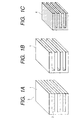
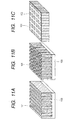
- Fig. 11A represents a piezoelectric element utilized for a one-dimensional array-type ultrasonic probe
- Fig. 11B represents a piezoelectric element utilized for a two-dimensional array-type ultrasonic probe
- Fig. 11C represents a piezoelectric composite material.
- reference numeral 101, 102 and 103 denote piezoelectric ceramic, filler and substrate, respectively, and each of the structures has an arrangement in which a number of fine plate-shaped or column-shaped piezoelectric ceramics are arranged and a filler of such as resin fills gap portions between the piezoelectric ceramics mentioned above such as shown in Fig. 11C.
- piezoelectric ceramic used herein will mean inclusively piezoelectric ceramic layer or column.
- the one-directional array-type piezoelectric element shown in Fig. 1A is cut by using a cutting machine such as dicing saw in a direction perpendicular to the preliminarily cut direction with a predetermined design width. That is, the piezoelectric ceramics 101 are cut so as to provide two-dimensional structure shown in Fig. 11B including a number of piezoelectric ceramic columns.
- one- or two-dimensional array-type ultrasonic probe could be manufactured by utilizing the piezoelectric elements or structures such as shown in Fig. 11A or 11B.
- a composite piezoelectric material such as shown in Fig. 11C by filling a filler 2 in grooves or gaps formed by cutting the piezoelectric ceramic columns of Fig. 11B.
- An object of the present invention is to substantially eliminate defects or drawbacks encountered in the prior art mentioned above and to provide a piezoelectric element composed of fine piezoelectric ceramics having uniform and high characteristic particularly such as piezoelectric element arranged with piezoelectric ceramics having high aspect ratio or piezoelectric element having a curved surface which was difficult to be manufactured by a conventional machine working .
- Another object of the present invention is to provide a method of manufacturing a piezoelectric element of the characters mentioned above with high yielding.
- a piezoelectric element characterized in that a composite is formed from a piezoelectric precursor prepared by mixing a powder containing piezoelectric material with a binder material and a gap forming material filling a gap formed to the piezoelectric precursor and the gap forming material is then removed from the composite.
- the gap formed by removing the gap forming material is filled up with a filler.
- the composite has sectional areas continuous at least in one direction so as to provide a same pattern.
- the composite is formed by the piezoelectric precursor and the gap forming material in shape of sheets or plates, which are laminated in a predetermined order.
- the composite is formed as a composite roll.
- the composite is formed by laminating a plurality of composite plate members, in a thickness direction thereof, in which the piezoelectric precursor and the gap forming material are arranged at least in one direction perpendicular to the thickness direction thereof.
- the composite is formed by laminating a plurality of composite plate members, in a thickness direction thereof, in which the piezoelectric precursor and the gap forming material are arranged at least in one direction perpendicular to the thickness direction thereof and piezoelectric precursors in form of sheets in a predetermined order.
- the composite is formed by laminating a plurality of composite plate members, in a thickness direction thereof, in which the piezoelectric precursor and the gap forming material are arranged at least in one direction perpendicular to the thickness direction thereof and gap forming materials in form of sheets in a predetermined order.
- the composite is formed by coating, in an overlapped manner, the piezoelectric precursor and the gap forming material both having fluidity so as to provide a predetermined pattern.
- the composite is formed by applying the piezoelectric precursor in a mold formed of the gap forming material.
- an ultrasonic probe formed from the piezoelectric element mentioned above though not mentioned in detail herein.
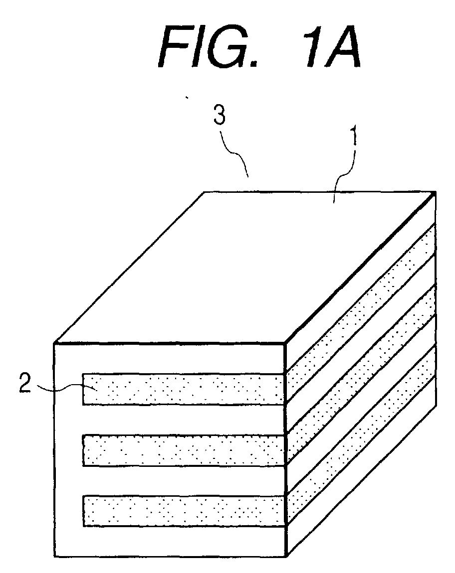
- Figs. 1A to 1C are schematic views representing the manufacturing processes of a piezoelectric element according to a first embodiment of the present invention such as shown, and for example, the processes are for manufacturing a piezoelectric element utilized for a one-dimensional array type ultrasonic probe shown in Fig. 11A.
- the piezoelectric element shown in Fig. 11A has a structure in which plate (sheet)-shaped piezoelectric ceramics are arranged with predetermined gap (interval) in the thickness direction thereof.
- Fig. 1A shows a process for forming a composite piezoelectric material body 3 (which may be called hereunder composite or composite material) by alternately laminating piezoelectric precursor 1 and gap forming material 2
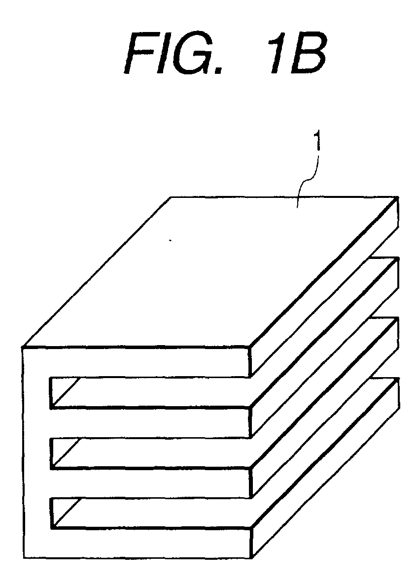
- Fig. 1B shows a process for removing the gap forming materials from the formed composite 3
- Fig. 1C shows a process for forming a piezoelectric element 4 by sintering the remaining piezoelectric precursor 1.
- the piezoelectric precursors 1 and the gap forming material 2 are formed in form of sheets or layers and laminated in a predetermined order as shown in Fig. 2A to thereby form the composite 3 shown in Fig. 1A.
- Pressure and heat may be applied as occasion demands at the time of lamination of the piezoelectric precursor and the gap forming material 2.
- the sheet of the piezoelectric precursor 1 may be formed by mixing piezoelectric ceramic powder and a binder (and if required, a plasticizer may be added), dissolving the mixture in a solvent and then forming it into sheet shape through a doctor blade method or like.
- the piezoelectric precursor 1 may be formed into a block which is then sliced into sheet shape.
- the methods of forming the gap forming material 2 into sheet shape are different from each other in accordance with materials to be used.
- materials to be used for example, in a case of using resin or like material for the gap forming material 2, the method utilized for the piezoelectric precursor 1 mentioned above will be also utilized.
- metal material for the gap forming material 2 there will be selected a material from commercially sold metal plates having a desired thickness satisfying predetermined conditions, for example, such a requirement as not being reacted to the piezoelectric precursor 1.
- a material or substance which is not reacted to the piezoelectric ceramic or binder material, and materials or substances other than those mentioned above may be utilized.
- the piezoelectric precursor 1 and the gap forming material 2 dissolved in a solvent into liquid form are coated and then dried repeatedly in a predetermined order.
- the gap forming material 2 is removed from the composite 3 manufactured in the methods mentioned above. Further, in the case where the gap forming material 2 is formed of resin material or like, it may be possible to burn it in a high temperature atmosphere to thereby remove the gap forming material 2 in a gaseous state. In this step, it is necessary to control burning conditions so as not to generate crack or like to the piezoelectric precursor 1 by a pressure at a time of gasifying of the gap forming material 2.
- the composite will be formed with no generation of defects such as peeling or like by providing the sheet of the piezoelectric precursor 1 with a large compression deformation rate having a value capable of absorbing the thickness of the sheet of the gap forming material 2.
- the compression rate at the time of lamination largely differs at a portion where the gap forming material sheet is present or a portion where it is not present. Because of this reason, the density of the piezoelectric precursor 1 in the composite 3 differs in portions, and hence, the compression rate differs at portions at the sintering time.
- the composite 3 including the piezoelectric precursor 1 be formed with a desired shape, it will be deformed during the sintering process of the piezoelectric precursor 1, and therefore, it becomes difficult to manufacture the piezoelectric element 4 having a desired shape with high precision.
- Fig. 2B it is desired to dispose the piezoelectric precursor sheets, each having the same thickness as that of the gap forming material 2, to portions of the gap forming material arranging layers at which the gap forming material 2 is not present, and after the arrangement of such piezoelectric precursor sheets, these layers are to be laminated.
- Fig. 2A it is possible to remove the difference in the compression rate of the piezoelectric ceramic in the composite 3 at the sintering time while maintaining a portion constituting a wide gap by laminating the thick gap forming material sheets 2, thus being advantageous.
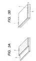
- Fig. 3 is an illustration for forming the composite 3 by laminating, in the predetermined order, the composite sheet 5 composed of the piezoelectric precursor 1 and the gap forming material 2 and the sheet of the gap forming material 2.
- the composite sheet 5 formed by removing at least one end face of the gap forming material 2 formed on a carrier film 6 formed of such as PET (polyethylene terephtalate) or like (Fig. 3A) and, thereafter, forming the sheet of the piezoelectric precursor 1 on the gap forming material 2 by a doctor blade method (Fig. 3B).
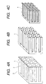
- a piezoelectric element and a method of manufacturing the same , the piezoelectric element being one for two-dimensional array-type ultrasonic probe such as shown in Figs. 11B and 11C; that is, one like a piezoelectric composite material in which columnar piezoelectric ceramics are arranged.
- Fig. 4A shows the structure in which the piezoelectric precursor 1 are arranged in shape of columns with gaps into which the gap forming material 2 fills to thereby provide the piezoelectric composite 3.
- Fig. 4B shows the state that the gap forming material 2 is removed from the composite 3 of Fig. 4A
- Fig. 4C shows the steps of sintering the remaining piezoelectric precursor 1 for producing the piezoelectric element 4 utilized for, for example, the two-dimensional array-type ultrasonic probe and the composite piezoelectric material shown in Figs. 11B and 11C. The details of these steps will be further mentioned hereunder.
- the composite 3 shown in Fig. 4 is formed through the following steps, for example.
- the composite 3 shown in Fig. 1 is sliced into a plurality of sheets of composite in a direction perpendicular to the laminated direction of the composite 3, i.e. in the depth direction on the drawing paper, each having a thin thickness such as shown in Fig. 5A in which the piezoelectric precursor and the gap forming material are arranged in one sheet in a predetermined pattern.
- the composite 3 is formed, as like in the first embodiment, by dispersing or dissolving the piezoelectric precursor 1 and the gap forming material 2 into solvents in form of solutions, which are then applied in a predetermined pattern and then dried.
- the layer composed only of the gap forming material 2 can be entirely uniformly coated.
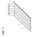
- a layer including the piezoelectric precursor 1 a layer of the piezoelectric precursor 1 and the gap forming material 2 of a desired pattern can be formed by supplying the piezoelectric precursor 1 and the gap forming material 2 at a predetermined amount through a supply member 7, for example, fine tube, in accordance with the predetermined pattern such as shown in Fig. 7.
- solvents having different polarities such as hydrophilic and hydrophobic solvents, in which the piezoelectric precursor 1 and the gap forming material 2 are dissolved.
- the composite 3 is formed by laminating the layer in which the piezoelectric precursor 1 and the gas forming material 2 are patterned and the layer of the gap forming material 2.
- piezoelectric elements 4 having various shapes which are difficult to be formed by a usual machine working, can be produced by repeatedly laminating the layers in which the piezoelectric precursor 1 and the gap forming material 2 are patterned respectively as shown in Fig. 8A or by forming the composite 3 by laminating the layer in which the piezoelectric precursor 1 and the gap forming material 2 are patterned and the layer of the piezoelectric precursor 1.
- the piezoelectric precursor 1 fills in a mold formed of the gap forming material 2, which will be represented by Fig. 9.
- Fig. 9 including Figs. 9A, 9B and 9C, represents amethod of manufacturing the piezoelectric material 3a having a structure in which the two-dimensional array-type ultrasonic probe and the columnar piezoelectric ceramics such as piezoelectric composite material are arranged.
- Fig. 9A there is formed a mold of the gap forming material 2 having a pattern having a shape reverse to that of an aimed piezoelectric element 4.
- the mold of the gap forming material 2 will be manufactured by, for example, the following manner.
- an original mold having a shape similar to the piezoelectric material (composite) 3a is first prepared.
- the dimension of the original mold will be determined in consideration of a coefficient of contraction (shrinkage factor) at the sintering time of the piezoelectric precursor 1.
- An original mold for forming the gap forming material 2 will be formed by carrying out an electric discharging working or dicing working to metal or ceramic. Further, since the original mold is a mold merely for forming the mold of the gap forming material 2, it is not necessary to form a lot of such molds even in the case of manufacturing a number of piezoelectric elements 4.
- the surrounding of the original mold, formed as shown in Fig. 9B, is covered by, for example, a tape or like means for forming a wall section to the mold, and then, the gap of the original mold covered by the wall section is filled up with the gap forming material 2.
- the gap forming material 2 it is desired for the gap forming material 2 to have a fluidity so as to be entirely spread in the gap of the original mold.
- the gap forming material utilized for this manufacturing method it is preferred to use a resin or like material, which is capable of being dispersed or dissolved in the solvent or which has a good fluidity at not-hardened state.
- the piezoelectric precursor 1 fills the gap in a state separating from the original mold, it is desired to provide a surface layer on the surface of the original mold for the easy peeling-off of the gap forming material 2 therefrom.
- the surface layer formed of fluorine material preferably of Teflon.
- the piezoelectric precursor 1 fills the mold of the gap forming material 2 formed from the original mold in the manner described hereinbefore, and through this manner, the composite 3 is formed.
- the piezoelectric element 4 it is not necessary to perform a fine machine working to the sintered piezoelectric ceramic, and it becomes possible to manufacture the piezoelectric element 4 in which a number of piezoelectric ceramics, such as shown in Fig. 11, each having fine structure are arranged with high precision and high yielding. Furthermore, according to this method, the piezoelectric ceramic is substantially free from cracks or like defects, so that the piezoelectric performance or characteristics can be made further high and uniform.
- the shape of the piezoelectric element 4 is influenced by the width of the working tool.
- such influence is not caused, so that the piezoelectric element 4 having the fine structure can be manufactured, which is capable of being applicable for high frequencies, for example.
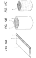
- FIG. 10 A third embodiment of the present invention will be described hereunder with reference to Fig. 10, including Figs . 10A, 10B and 10C.
- at least one layer of the piezoelectric precursor 1 and at least one layer of gap forming material 2 are laminated as shown in Fig. 10A, and the lamination layer is then rolled up as a roll of the composite 3 as shown in Fig. 10B.
- the gap forming material 2 is thereafter removed from such composite material roll 3 and the thus formed piezoelectric precursor 1 is sintered to thereby provide the piezoelectric element 4 such as shown in Fig. 10C.
- the composite material 3 formed by laminating the piezoelectric precursor 1 and the gap forming material 2 and rolling up them it may be possible to manufacture composite materials by folding the composite 3 of the lamination of the piezoelectric precursor 1 and the gap forming material 2 into a bellows form, into a spiral form or like form, to thereby provide piezoelectric elements 4 having various forms or shapes.
- the piezoelectric elements in which a number of fine piezoelectric ceramics are arranged or which have complicated curved surfaces, which have been extremely hard to be manufactured by the conventional machine working, can be manufactured at once with high precision and high yielding with low manufacturing cost.
Landscapes
- Engineering & Computer Science (AREA)
- Chemical & Material Sciences (AREA)
- Composite Materials (AREA)
- Materials Engineering (AREA)
- Manufacturing & Machinery (AREA)
- Transducers For Ultrasonic Waves (AREA)
- Ultra Sonic Daignosis Equipment (AREA)
- Apparatuses For Generation Of Mechanical Vibrations (AREA)
- Compositions Of Oxide Ceramics (AREA)
Abstract
Description
Claims (19)
- A piezoelectric element characterized in that a composite is formed from a piezoelectric precursor prepared by mixing a powder containing piezoelectric material with a binder material and a gap forming material filling a gap formed to the piezoelectric precursor and the gap forming material is then removed from the composite.
- The piezoelectric element according to claim 1, wherein, the gap formed by removing the gap forming material is filled up with a filler.
- The piezoelectric element according to claim 1 or 2, wherein the composite has sectional areas continuous at least in one direction so as to provide a same pattern.
- The piezoelectric element according to any one of claims 1 to 3, wherein the composite is formed by the piezoelectric precursor and the gap forming material in shape of sheets, which are laminated in a predetermined order.
- The piezoelectric element according to claim 4, wherein the composite is formed as a composite roll.
- The piezoelectric element according to any one of claims 1 to 3, wherein the composite is formed by laminating a plurality of composite plate members, in a thickness direction thereof, in which the piezoelectric precursor and the gap forming material are arranged at least in one direction perpendicular to the thickness direction thereof.
- The piezoelectric element according to any one of claims 1 to 3, wherein the composite is formed by laminating a plurality of composite plate members, in a thickness direction thereof, in which the piezoelectric precursor and the gap forming material are arranged at least in one direction perpendicular to the thickness direction thereof and piezoelectric precursors in form of sheets in a predetermined order.
- The piezoelectric element according to any one of claims 1 to 3, wherein the composite is formed by laminating a plurality of composite plate members, in a thickness direction thereof, in which the piezoelectric precursor and the gap forming material are arranged at least in one direction perpendicular to the thickness direction thereof and gap forming materials in form of sheets in a predetermined order.
- The piezoelectric element according to any one of claims 1 to 3, wherein the composite is formed by coating, in an overlapped manner, the piezoelectric precursor and the gap forming material both having fluidity so as to provide a predetermined pattern.
- The piezoelectric element according to any one of claims 1 to 3, wherein the composite is formed by applying the piezoelectric precursor in a mold formed of the gap forming material.
- A method of manufacturing a piezoelectric element characterized in that a composite is formed from a piezoelectric precursor prepared by mixing a powder containing piezoelectric material with a binder material and a gap forming material filling a gap formed to the piezoelectric precursor and the gap forming material is then removed from the composite .
- The method of manufacturing a piezoelectric element according to claim 11, wherein the gap formed by removing the gap forming material is filled up with a filler.
- The method of manufacturing a piezoelectric element according to claim 12, wherein the composite is formed by laminating the precursor and the gap forming material in a predetermined order.
- The method of manufacturing a piezoelectric element according to claim 11, wherein the composite is formed as a roll.
- The method of manufacturing a piezoelectric element according to claim 11, wherein the composite is formed by laminating a plurality of composite members in shape of sheets, in a thickness direction thereof, in which the piezoelectric precursor and the gap forming material are arranged at least in one direction perpendicular to the thickness direction thereof.
- The method of manufacturing a piezoelectric element according to 11, wherein the composite is formed by laminating a plurality of composite members in shape of sheets, in a thickness direction thereof, in which the piezoelectric precursor and the gap forming material are arranged at least in one direction perpendicular to the thickness direction thereof and piezoelectric precursors in form of sheets in a predetermined order.
- The method of manufacturing a piezoelectric element according to 11, wherein the composite is formed by laminating a plurality of composite members in shape of sheets, in a thickness direction thereof, in which the piezoelectric precursor and the gap forming material are arranged at least in one direction perpendicular to the thickness direction thereof and gap forming materials in form of sheets in a predetermined order.
- The method of manufacturing a piezoelectric element according to 11, wherein the composite is formed by coating, in an overlapped manner, the piezoelectric precursor and the gap forming material both having fluidity so as to provide a predetermined pattern.
- The method of manufacturing a piezoelectric element according to claim 11, wherein the composite is formed by applying the piezoelectric precursor in a mold formed of the gap forming material.
Applications Claiming Priority (2)
| Application Number | Priority Date | Filing Date | Title |
|---|---|---|---|
| JP2000296293A JP3551141B2 (en) | 2000-09-28 | 2000-09-28 | Method of manufacturing piezoelectric body |
| JP2000296293 | 2000-09-28 |
Publications (2)
| Publication Number | Publication Date |
|---|---|
| EP1193777A2 true EP1193777A2 (en) | 2002-04-03 |
| EP1193777A3 EP1193777A3 (en) | 2005-04-20 |
Family
ID=18778589
Family Applications (1)
| Application Number | Title | Priority Date | Filing Date |
|---|---|---|---|
| EP20010308251 Withdrawn EP1193777A3 (en) | 2000-09-28 | 2001-09-27 | Method of manufacturing piezoelectric elements using sacrificial material |
Country Status (3)
| Country | Link |
|---|---|
| US (1) | US6538363B2 (en) |
| EP (1) | EP1193777A3 (en) |
| JP (1) | JP3551141B2 (en) |
Families Citing this family (19)
| Publication number | Priority date | Publication date | Assignee | Title |
|---|---|---|---|---|
| US20040254471A1 (en) * | 2003-06-13 | 2004-12-16 | Andreas Hadjicostis | Miniature ultrasonic phased array for intracardiac and intracavity applications |
| US20050251127A1 (en) * | 2003-10-15 | 2005-11-10 | Jared Brosch | Miniature ultrasonic transducer with focusing lens for intracardiac and intracavity applications |
| US7082655B2 (en) * | 2003-12-18 | 2006-08-01 | Ge Inspection Technologies, Lp | Process for plating a piezoelectric composite |
| JP4503347B2 (en) * | 2004-04-28 | 2010-07-14 | 日本電波工業株式会社 | Manufacturing method of ultrasonic probe |
| JP5036284B2 (en) * | 2006-11-22 | 2012-09-26 | 日本碍子株式会社 | Manufacturing method of ceramic structure |
| US7581296B2 (en) * | 2007-04-11 | 2009-09-01 | Ge Inspection Technologies, Lp | Acoustic stack for ultrasonic transducers and method for manufacturing same |
| CN203192864U (en) * | 2009-07-27 | 2013-09-11 | Cts公司 | Encapsulated ceramic element |
| US8561270B2 (en) * | 2010-02-22 | 2013-10-22 | Cts Corporation | Composite ceramic structure and method of making the same |
| US8680745B2 (en) | 2010-07-21 | 2014-03-25 | General Electric Company | Device for measuring material thickness |
| US8264129B2 (en) | 2010-07-21 | 2012-09-11 | General Electric Company | Device and system for measuring material thickness |
| CN102437282B (en) * | 2011-09-19 | 2013-12-25 | 南京航空航天大学 | Piezoelectric ceramic fibrous composite material and preparation method thereof |
| CN102376870B (en) * | 2011-12-02 | 2014-03-19 | 济南大学 | 1-3 type arch-shaped or circular ring piezoelectric composite material and preparing method thereof |
| US8857261B2 (en) | 2012-04-12 | 2014-10-14 | General Electric Company | Sensing device and method of attaching the same |
| CN103915561A (en) * | 2012-12-28 | 2014-07-09 | 中国科学院声学研究所 | Piezoelectric ceramic-polymer composites preparation method and piezoelectric ceramic-polymer composites |
| CN105405964B (en) * | 2015-12-10 | 2019-07-23 | 武汉理工大学 | A kind of preparation method of piezoelectric fiber composite structure layer |
| CN108701754B (en) * | 2016-02-18 | 2022-07-26 | 柯尼卡美能达株式会社 | Manufacturing method of piezoelectric element and piezoelectric element |
| CN109155359B (en) * | 2016-05-19 | 2022-06-10 | 柯尼卡美能达株式会社 | Method for manufacturing piezoelectric element |
| KR101850127B1 (en) * | 2017-03-16 | 2018-04-19 | 주식회사 베프스 | Manufacturing method for ultrasonic fingerprint sensor |
| CN119603602A (en) * | 2024-10-14 | 2025-03-11 | 北京理工大学 | A multifunctional mortise and tenon piezoelectric vibrator and its preparation method |
Family Cites Families (18)
| Publication number | Priority date | Publication date | Assignee | Title |
|---|---|---|---|---|
| DE3021449A1 (en) * | 1980-06-06 | 1981-12-24 | Siemens AG, 1000 Berlin und 8000 München | ULTRASONIC TRANSDUCER ARRANGEMENT AND METHOD FOR THE PRODUCTION THEREOF |
| DE3434729A1 (en) * | 1984-09-21 | 1986-04-03 | Siemens AG, 1000 Berlin und 8000 München | Flexural element made of piezoceramic, and method for the fabrication thereof |
| JPH01208879A (en) * | 1988-02-17 | 1989-08-22 | Oki Electric Ind Co Ltd | Manufacture of composite piezoelectric element |
| JPH01223785A (en) * | 1988-03-03 | 1989-09-06 | Oki Electric Ind Co Ltd | Manufacture of composite piezoelectric material |
| US4890268A (en) * | 1988-12-27 | 1989-12-26 | General Electric Company | Two-dimensional phased array of ultrasonic transducers |
| US5121329A (en) * | 1989-10-30 | 1992-06-09 | Stratasys, Inc. | Apparatus and method for creating three-dimensional objects |
| DE68926166T2 (en) * | 1989-11-14 | 1996-12-12 | Battelle Memorial Institute | Method of making a piezoelectric stack drive device |
| US5137776A (en) * | 1990-09-27 | 1992-08-11 | The United States Of America As Represented By The Secretary Of The Navy | Metal-coated, ordered void piezoelectric ceramic material |
| US5744898A (en) * | 1992-05-14 | 1998-04-28 | Duke University | Ultrasound transducer array with transmitter/receiver integrated circuitry |
| JP3279721B2 (en) * | 1993-03-26 | 2002-04-30 | 太平洋セメント株式会社 | Multilayer piezoelectric actuator and method of manufacturing the same |
| US5359760A (en) * | 1993-04-16 | 1994-11-01 | The Curators Of The University Of Missouri On Behalf Of The University Of Missouri-Rolla | Method of manufacture of multiple-element piezoelectric transducer |
| US5539965A (en) * | 1994-06-22 | 1996-07-30 | Rutgers, The University Of New Jersey | Method for making piezoelectric composites |
| US5818149A (en) * | 1996-03-25 | 1998-10-06 | Rutgers, The State University Of New Jersey | Ceramic composites and methods for producing same |
| JP3882231B2 (en) | 1996-07-31 | 2007-02-14 | 住友電気工業株式会社 | Manufacturing method of composite piezoelectric material |
| DE19743859C2 (en) * | 1997-10-04 | 2000-11-16 | Stn Atlas Elektronik Gmbh | Method of manufacturing a composite ultrasonic transducer |
| JP4065049B2 (en) * | 1998-03-19 | 2008-03-19 | オリンパス株式会社 | Method for manufacturing piezoelectric ceramic structure and method for manufacturing composite piezoelectric vibrator |
| DE19814018A1 (en) * | 1998-03-28 | 1999-09-30 | Andreas Roosen | Ceramic-polymer, ceramic-ceramic or ceramic-metal composite, e.g. a piezoceramic-polymer composite for an ultrasonic transducer |
| JP2000050391A (en) * | 1998-07-31 | 2000-02-18 | Olympus Optical Co Ltd | Ultrasonic transducer and its manufacture |
-
2000
- 2000-09-28 JP JP2000296293A patent/JP3551141B2/en not_active Expired - Fee Related
-
2001
- 2001-09-27 EP EP20010308251 patent/EP1193777A3/en not_active Withdrawn
- 2001-09-28 US US09/964,362 patent/US6538363B2/en not_active Expired - Fee Related
Also Published As
| Publication number | Publication date |
|---|---|
| JP3551141B2 (en) | 2004-08-04 |
| US6538363B2 (en) | 2003-03-25 |
| JP2002111093A (en) | 2002-04-12 |
| EP1193777A3 (en) | 2005-04-20 |
| US20020036447A1 (en) | 2002-03-28 |
Similar Documents
| Publication | Publication Date | Title |
|---|---|---|
| US6538363B2 (en) | Method of manufacturing a piezoelectric element | |
| US5164920A (en) | Composite ultrasound transducer and method for manufacturing a structured component therefor of piezoelectric ceramic | |
| US7454820B2 (en) | Method of manufacturing a plurality of laminated structures | |
| EP1227525B1 (en) | Piezocomposite, ultrasonic probe for ultrasonic diagnostic equipment, ultrasonic diagnostic equipment and method for producing piezocomposite | |
| US9780288B2 (en) | Method of assembling an ultrasonic transducer and the transducer obtained thereby | |
| US20010017502A1 (en) | Multilayer piezoactuator and method for manufacturing same | |
| US7246420B2 (en) | Method for manufacturing a comb teeth type piezoelectric actuator | |
| JP3492421B2 (en) | Manufacturing method of multilayer ceramic electronic component | |
| US20040255443A1 (en) | Production method of stacked piezoelectric element | |
| JP2002280630A (en) | Piezoelectric ceramics multi-layer actuator and method for manufacturing the same | |
| JP2005123288A (en) | Manufacturing method for laminated electronic component | |
| JP3445262B2 (en) | Piezoelectric body manufacturing method, piezoelectric body, ultrasonic probe, ultrasonic diagnostic apparatus, and nondestructive inspection apparatus | |
| WO2025193840A1 (en) | Piezoelectric structure and additive manufacturing method | |
| Hackenberger et al. | Novel method for producing high frequency 2-2 composites from PZT ceramic | |
| US20060205097A1 (en) | Methods of manufacturing a crystal-oriented ceramic and of manufacturing a ceramic laminate | |
| JP2005213086A (en) | Tray for thermal treatment and method for producing ceramic product using the same | |
| EP1389805B1 (en) | Multislit type actuator, inkjet head, and method for manufacturing multislit type actuator | |
| EP2423993B1 (en) | Manufacturing method for thin board-shaped fired piezoelectric body | |
| JP2003017779A (en) | Manufacturing method of ceramic laminate | |
| JPH0779026A (en) | Piezoelectric actuator and its manufacture | |
| CN114175328B (en) | Electrolyte sheet for solid oxide fuel cell, method for producing electrolyte sheet for solid oxide fuel cell, and single cell for solid oxide fuel cell | |
| JP2006100805A (en) | Piezoelectric actuator and manufacturing method thereof | |
| JP2003258332A (en) | Manufacturing method for ceramic laminate | |
| JP2025133317A (en) | Gravure printing plate | |
| JPS60249500A (en) | Production for two-dimensional array transducer |
Legal Events
| Date | Code | Title | Description |
|---|---|---|---|
| PUAI | Public reference made under article 153(3) epc to a published international application that has entered the european phase |
Free format text: ORIGINAL CODE: 0009012 |
|
| AK | Designated contracting states |
Kind code of ref document: A2 Designated state(s): AT BE CH CY DE DK ES FI FR GB GR IE IT LI LU MC NL PT SE TR |
|
| AX | Request for extension of the european patent |
Free format text: AL;LT;LV;MK;RO;SI |
|
| PUAL | Search report despatched |
Free format text: ORIGINAL CODE: 0009013 |
|
| AK | Designated contracting states |
Kind code of ref document: A3 Designated state(s): AT BE CH CY DE DK ES FI FR GB GR IE IT LI LU MC NL PT SE TR |
|
| AX | Request for extension of the european patent |
Extension state: AL LT LV MK RO SI |
|
| AKX | Designation fees paid |
Designated state(s): DE FR GB |
|
| STAA | Information on the status of an ep patent application or granted ep patent |
Free format text: STATUS: THE APPLICATION IS DEEMED TO BE WITHDRAWN |
|
| 18D | Application deemed to be withdrawn |
Effective date: 20051021 |