EP1193691A1 - Converter support structure - Google Patents
Converter support structure Download PDFInfo
- Publication number
- EP1193691A1 EP1193691A1 EP00927786A EP00927786A EP1193691A1 EP 1193691 A1 EP1193691 A1 EP 1193691A1 EP 00927786 A EP00927786 A EP 00927786A EP 00927786 A EP00927786 A EP 00927786A EP 1193691 A1 EP1193691 A1 EP 1193691A1
- Authority
- EP
- European Patent Office
- Prior art keywords
- transducer
- suspension
- supporting structure
- medium
- structure according
- Prior art date
- Legal status (The legal status is an assumption and is not a legal conclusion. Google has not performed a legal analysis and makes no representation as to the accuracy of the status listed.)
- Withdrawn
Links
Images







Classifications
-
- G—PHYSICS
- G11—INFORMATION STORAGE
- G11B—INFORMATION STORAGE BASED ON RELATIVE MOVEMENT BETWEEN RECORD CARRIER AND TRANSDUCER
- G11B5/00—Recording by magnetisation or demagnetisation of a record carrier; Reproducing by magnetic means; Record carriers therefor
- G11B5/127—Structure or manufacture of heads, e.g. inductive
-
- G—PHYSICS
- G11—INFORMATION STORAGE
- G11B—INFORMATION STORAGE BASED ON RELATIVE MOVEMENT BETWEEN RECORD CARRIER AND TRANSDUCER
- G11B11/00—Recording on or reproducing from the same record carrier wherein for these two operations the methods are covered by different main groups of groups G11B3/00 - G11B7/00 or by different subgroups of group G11B9/00; Record carriers therefor
- G11B11/10—Recording on or reproducing from the same record carrier wherein for these two operations the methods are covered by different main groups of groups G11B3/00 - G11B7/00 or by different subgroups of group G11B9/00; Record carriers therefor using recording by magnetic means or other means for magnetisation or demagnetisation of a record carrier, e.g. light induced spin magnetisation; Demagnetisation by thermal or stress means in the presence or not of an orienting magnetic field
- G11B11/105—Recording on or reproducing from the same record carrier wherein for these two operations the methods are covered by different main groups of groups G11B3/00 - G11B7/00 or by different subgroups of group G11B9/00; Record carriers therefor using recording by magnetic means or other means for magnetisation or demagnetisation of a record carrier, e.g. light induced spin magnetisation; Demagnetisation by thermal or stress means in the presence or not of an orienting magnetic field using a beam of light or a magnetic field for recording by change of magnetisation and a beam of light for reproducing, i.e. magneto-optical, e.g. light-induced thermomagnetic recording, spin magnetisation recording, Kerr or Faraday effect reproducing
- G11B11/10532—Heads
- G11B11/10534—Heads for recording by magnetising, demagnetising or transfer of magnetisation, by radiation, e.g. for thermomagnetic recording
-
- G—PHYSICS
- G11—INFORMATION STORAGE
- G11B—INFORMATION STORAGE BASED ON RELATIVE MOVEMENT BETWEEN RECORD CARRIER AND TRANSDUCER
- G11B11/00—Recording on or reproducing from the same record carrier wherein for these two operations the methods are covered by different main groups of groups G11B3/00 - G11B7/00 or by different subgroups of group G11B9/00; Record carriers therefor
- G11B11/10—Recording on or reproducing from the same record carrier wherein for these two operations the methods are covered by different main groups of groups G11B3/00 - G11B7/00 or by different subgroups of group G11B9/00; Record carriers therefor using recording by magnetic means or other means for magnetisation or demagnetisation of a record carrier, e.g. light induced spin magnetisation; Demagnetisation by thermal or stress means in the presence or not of an orienting magnetic field
- G11B11/105—Recording on or reproducing from the same record carrier wherein for these two operations the methods are covered by different main groups of groups G11B3/00 - G11B7/00 or by different subgroups of group G11B9/00; Record carriers therefor using recording by magnetic means or other means for magnetisation or demagnetisation of a record carrier, e.g. light induced spin magnetisation; Demagnetisation by thermal or stress means in the presence or not of an orienting magnetic field using a beam of light or a magnetic field for recording by change of magnetisation and a beam of light for reproducing, i.e. magneto-optical, e.g. light-induced thermomagnetic recording, spin magnetisation recording, Kerr or Faraday effect reproducing
- G11B11/1055—Disposition or mounting of transducers relative to record carriers
- G11B11/1058—Flying heads
-
- G—PHYSICS
- G11—INFORMATION STORAGE
- G11B—INFORMATION STORAGE BASED ON RELATIVE MOVEMENT BETWEEN RECORD CARRIER AND TRANSDUCER
- G11B21/00—Head arrangements not specific to the method of recording or reproducing
- G11B21/16—Supporting the heads; Supporting the sockets for plug-in heads
- G11B21/20—Supporting the heads; Supporting the sockets for plug-in heads while the head is in operative position but stationary or permitting minor movements to follow irregularities in surface of record carrier
- G11B21/21—Supporting the heads; Supporting the sockets for plug-in heads while the head is in operative position but stationary or permitting minor movements to follow irregularities in surface of record carrier with provision for maintaining desired spacing of head from record carrier, e.g. fluid-dynamic spacing, slider
-
- G—PHYSICS
- G11—INFORMATION STORAGE
- G11B—INFORMATION STORAGE BASED ON RELATIVE MOVEMENT BETWEEN RECORD CARRIER AND TRANSDUCER
- G11B5/00—Recording by magnetisation or demagnetisation of a record carrier; Reproducing by magnetic means; Record carriers therefor
- G11B2005/0002—Special dispositions or recording techniques
- G11B2005/0005—Arrangements, methods or circuits
-
- G—PHYSICS
- G11—INFORMATION STORAGE
- G11B—INFORMATION STORAGE BASED ON RELATIVE MOVEMENT BETWEEN RECORD CARRIER AND TRANSDUCER
- G11B5/00—Recording by magnetisation or demagnetisation of a record carrier; Reproducing by magnetic means; Record carriers therefor
- G11B2005/0002—Special dispositions or recording techniques
- G11B2005/0005—Arrangements, methods or circuits
- G11B2005/0021—Thermally assisted recording using an auxiliary energy source for heating the recording layer locally to assist the magnetization reversal
-
- G—PHYSICS
- G11—INFORMATION STORAGE
- G11B—INFORMATION STORAGE BASED ON RELATIVE MOVEMENT BETWEEN RECORD CARRIER AND TRANSDUCER
- G11B5/00—Recording by magnetisation or demagnetisation of a record carrier; Reproducing by magnetic means; Record carriers therefor
- G11B5/40—Protective measures on heads, e.g. against excessive temperature
-
- G—PHYSICS
- G11—INFORMATION STORAGE
- G11B—INFORMATION STORAGE BASED ON RELATIVE MOVEMENT BETWEEN RECORD CARRIER AND TRANSDUCER
- G11B5/00—Recording by magnetisation or demagnetisation of a record carrier; Reproducing by magnetic means; Record carriers therefor
- G11B5/48—Disposition or mounting of heads or head supports relative to record carriers ; arrangements of heads, e.g. for scanning the record carrier to increase the relative speed
- G11B5/4806—Disposition or mounting of heads or head supports relative to record carriers ; arrangements of heads, e.g. for scanning the record carrier to increase the relative speed specially adapted for disk drive assemblies, e.g. assembly prior to operation, hard or flexible disk drives
Definitions
- the present invention relates to a structure for supporting a transducer for recording or reproducing information on or from a recording medium mainly by an interaction with the recording medium, specifically, by the action of light, heat, magnetic field, or the like.
- a structure for supporting a magnetic core for magnetic recording is cited.
- a magnetic tape or a flexible disk has been used, and in recent years, a minidisk (hereinafter abbreviated to MD) has been widely used as a magneto-optical recording medium mainly for music.
- the MD is based on the use of a sliding-type magnetic head slider for magneto-optical field modulation overwrite.
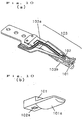
- FIG. 10(a) shows an entire structure.
- reference numeral 101 denotes a slider serving as a transducer mounting section.
- the main function of the transducer mounting section is to interface with a medium.
- the slider comes into slidable contact with the medium to maintain a distance between a transducer and the medium.
- the slider for a fixedmagnetic disk keeps the distance between the transducer and the medium by means of floating.
- the contact pressure between the medium and the transducer is decreased by the expansion of sliding face, by which the transducer is prevented from wearing.
- the slider 101 is mounted with a magnetic core 102 having an E shape in cross section, formed of ferrite etc., and a coil 104 (described later), both of which serve as a transducer.
- Reference numeral 103 denotes a suspension formed of a metallic elastic material such as stainless steel, beryllium copper, andphosphor bronze.
- the slider 101 is connected to the distal end of the suspension 103.
- FIG. 10(b) The details of the sliding face of the slider 101, which have been disclosed in Japanese Patent Laid-Open No. 7-129902, are shown in FIG. 10(b).
- a cylindrical face 101a that comes into contact with a disk 10 (described later) is formed as a sliding face.
- Reference numeral 102a denotes a magnetic pole exposed on the disk side of the magnetic core 102.
- the cylindrical face 101a projects by a predetermined amount toward the disk from the magnetic pole 102a.
- the slider 101 including the cylindrical face 101a uses a slidable resin material having high wear resistance and some degree of lubricity on the face opposed to disk, which has an effect of preventing the slider 101 and the disk 10 from wearing.
- FIG. 11 shows an essential part of the distal end of a magnetic head structure.
- a tongue 103c is formed at the distal end of the suspension 103, and is connected to the slider 101.
- a spring portion 103a is deformed elastically to apply a predetermined load in the direction toward the disk to the slider 101.
- a gimbal portion 103b is deformed elastically to keep the relative posture of the slider 101 and the disk 10 with respect to the disk inclination, so that the magnetic pole 102a is brought close to a recording film of the disk 10.
- FIG. 12 shows a sliding state.
- the slider 101 serving as a transducer mounting section has a box portion.
- the aforementioned magnetic core 102 is housed and fixed, and also an inside bottom face S of the box portion, which is in contact with the lower end face of the magnetic core 102, plays a role in determining the relative height of the magnetic core 102.
- the disk 10 moves in the direction indicated by an arrow A.
- a modulated magnetic field produced by the coil 104 is induced by the magnetic core 102 and is applied from the magnetic pole 102a to the recording film heated by a converged laser beam, by which thermomagnetic recording is performed.
- the consumed electric power turns to heat, which raises the temperatures of both of the magnetic core 102 and the coil 104. Since the slider 101 is made of a resin material, which is a kind of thermal insulator, it is difficult to dissipate the heat of the electromagnetic transducer within the slider 101, so that slight generation of heat leads to a great increase in temperature.
- a magnetic material used for the magnetic core etc. generally has a Curie point.
- a temperature rise exceeding the Curie point due to the generation of heat loses the magnetism and extremely decreases the impedance. Therefore, there occurs a thermorunaway phenomenon that a large current flows, resulting in a temperature rise, and finally the burning of coil and the destruction of driving circuit take place.
- a shorter wavelength is important to high-density recording and reproduction.
- light with a short wavelength has high energy, so that heat is generated greatly.
- the operating temperature has a great influence on the service life, so that a shorter wavelength cannot be achieved easily.
- the magnetic core 102 is fixed to the slider 101 by means of bonding etc.
- a change in temperature occurs as described above, and the coefficient of thermal expansion differs greatly between the magnetic core 102 and the slider 101.
- the slider 101 has a poor adhesive property because of being made of a slidable resin. Therefore, if thermal expansion and contraction are repeated for a long period of time, there arises a problem of reliability in that adhesion is lost, and thus the magnetic core 102 floats from the slider 101, so that a sufficient magnetic field cannot be given to the recording film.
- the present invention has been achieved to solve the above problems, and accordingly an object thereof is to provide a highly reliable transducer-supporting structure in which a rise in temperature is reduced, whereby the performance can be enhanced easily.
- a 1st invention of the present invention is a transducer-supporting structure, characterized in that said structure at least comprises:
- a 2nd invention of the present invention is the transducer-supporting structure according to the 1st invention, characterized in that said thermal coupling member has an elastic restoring force, and is in contact with said transducer.
- a 3rd invention of the present invention (corresponding to claim 3) is the transducer-supporting structure according to the 1st invention, characterized in that said thermal coupling member is formed of a part of said suspension.
- a 4th invention of the present invention is the transducer-supporting structure according to the 1st invention, characterized in that said thermal coupling member and said transducer or said thermal coupling member and said suspension are partially coupled thermally with each other via a viscous fluid.
- a 5th invention of the present invention is the transducer-supporting structure according to the 1st invention, characterized in that said thermal coupling member is a gel-form substance, and said transducer and said suspension are coupled thermally with each other via said gel-form substance.
- a 6th invention of the present invention is the transducer-supporting structure according to the 1st invention, characterized in that said transducer is an electromagnetic transducer.
- a 7th invention of the present invention is the transducer-supporting structure according to the 1st invention, characterized in that said transducer is an electro-optical transducer .
- An 8th invention of the present invention is a transducer-supporting structure, characterized by at least comprising:
- a 9th invention of the present invention is the transducer-supporting structure according to the 8th invention, characterized in that said heat dissipating means is formed integrally with said transducer.
- a 10th invention of the present invention is the transducer-supporting structure according to the 8th invention, characterized in that said transducer is an electromagnetic transducer.
- An 11th invention of the present invention is the transducer-supporting structure according to the 8th invention, characterized in that said transducer is an electro-optical transducer.
- a 12th invention of the present invention is a transducer-supporting structure, characterized in that said structure at least comprises:
- a 13th invention of the present invention is the transducer-supporting structure according to the 12th invention, characterized in that heat generated in said transducer is transmitted to said suspension through said directly contacting portion, and is dissipated.
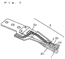
- FIG. 1 is a general view of a transducer-supporting structure in accordance with a first embodiment of the present invention.
- a slider 1 and a magnetic core 2 are the same as the slider 101 and the magnetic core 102 in the conventional example in respect of material and detailed construction.
- Reference numeral 3 denotes a suspension.
- the suspension 3 corresponds to the suspension 103 in the conventional example.
- a spring portion 3a and a gimbal portion 3b are the same as the spring portion 103a and the gimbal portion 103b in the conventional example.
- FIG. 2 shows an essential part of the transducer-supporting structure in accordance with the first embodiment of the present invention.
- a tongue 3c which is the same as the tongue 103c in the conventional example, is connected to the slider 1.
- Reference numeral 3d denotes a thermally coupling contact portion serving as a thermal coupling member and a contact portion.
- the thermally coupling contact portion 3d is configured so as to extend from the tongue 3c as a part of the suspension 3, and the end part thereof is in contact with the magnetic core 2, which forms a part of an electromagnetic transducer, with a relatively wide area.
- the slider 1 is mounted with the magnetic core 2 and a coil 4, serving as an electromagnetic transducer.
- the coil 4 is the same as the coil 104 in the conventional example.
- the thermally coupling contact portion 3d presses the magnetic core 2 on the slider 1 to position and fix the magnetic core 2 by means of a residual elastic restoring force.
- the spring portion 3a is deformed elastically to apply a predetermined load in the direction toward the disk to the slider 1.
- a gimbal portion 3b is deformed elastically to. keep the relative posture of the slider 1 and the disk 10 with respect to the disk inclination, so that a magnetic pole 2a is brought close to a recording film of the disk 10.
- thermomagnetic recording is performed.
- the electric power consumed in the electromagnetic transducer composed of the magnetic core 2 and the coil 4 turns to heat, which raises the temperature.
- the thermally coupling contact portion 3d which is a part of the suspension 3
- the thermal resistance between the thermally coupling contact portion 3d and the magnetic core 2 is low.
- the suspension 3, which is a good conductor formed of a metal such as stainless steel and beryllium copper, has high thermal conductivity due to free electrons.
- a rise in temperature of the magnetic core 2 can be restrained, and also a rise in temperature of the coil 4 connected to the magnetic core 2 can also be restrained.
- the thermally coupling contact portion 3d always presses the magnetic core 2 on the slider 1 in the insertion direction, the floating of the magnetic core 2 due to thermal expansion etc. can be prevented.
- the thermally coupling contact portion 3d is formed by integrating a thermal coupling member for inducing heat flow in the suspension 3 with a contact portion for pressing the magnetic core 2 on the slider 1 in this embodiment, the thermal coupling member and the contact portion may be separate parts, for example, to make optimum design of these elements individually.
- thermally coupling contact portion 3d which is formed of the suspension 3, that is, formed by extending the tongue 3c has been described as an example in the above-described embodiment
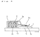
- a separate elastic member 3e with high thermal conductivity may be interposed between the tongue 3c and the magnetic core 2 as shown in FIG. 4.
- the thermally coupling contact portion 3d is in contact with the magnetic core 2 forming a part of a transducer in this embodiment, the thermally coupling contact portion 3d can be brought into contact with the coil 4 while an eddy current loss, a short circuit, and the like troubles are avoided by interposing a spacer 9 or the like as shown in FIG. 5.
- a change in height of the coil 4 can be restrained, the inductance can be stabilized, and the efficiency of magnetic flux with respect to the coil current can be kept at a high level.
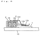
- FIG. 6 shows an essential part of a transducer-supporting structure in accordance with a second embodiment of the present invention.
- a slider 1, a magnetic core 2, a coil 4, and a disk 10 are the same as those elements of the first embodiment.
- the whole of a suspension 13 is not shown in FIG. 6, the suspension 13 is approximately the same as the suspension 3 of the first embodiment, and a gimbal portion 13b is the same as the gimbal portion 3b of the first embodiment.
- a tongue 13c is the same as the tongue 3c of the first embodiment, and is connected to the slider 1.
- Reference numeral 13d denotes a thermally coupling contact portion serving as a thermal coupling member and a contact portion.
- the thermally coupling contact portion 13d is configured so as to extend from the tongue 13c as a part of the suspension 13, and the tip end thereof is formed into a substantially arcuate shape so as to be in point or line contact with a substantially central portion of the magnetic core 2, which forms a part of an electromagnetic transducer.
- the thermally coupling contact portion 13d presses the magnetic core 2 on the slider 1 to position and fix the magnetic core 2 by means of a residual elastic restoring force.
- Reference numeral 15 denotes a viscous liquid material with relatively high thermal conductivity, such as a gel-form heat conductive material.
- a viscous liquid material with relatively high thermal conductivity such as a gel-form heat conductive material.
- silicone grease is preferably selected as the heat conductive material 15.
- the heat conductive material 15 is stuck in the vicinity of a contact region of the thermally coupling contact portion 13d and the magnetic core 4.
- transducer-supporting structure constructedas described above is approximately the same as those of the first embodiment, so that an explanation thereof is omitted, and different points will mainly be described.
- the thermally coupling contact portion 13d presses the magnetic core 2 toward the slider 1 to prevent the magnetic core 2 from floating.
- the thermally coupling contact portion 13d presses the magnetic core 2 while being in point or line contact with a substantially central portion of the magnetic core 2, the inclination of pressing force in the direction of insertion of the magnetic core 2 is small, so that the inclination of the magnetic core 2 can be prevented.
- the thermal resistance at the direct contact point of these elements is high.
- the heat conductive material 15 stuck in the vicinity of the contact region thermally couples the thermally coupling contact portion with the magnetic core 2 in a wide area, so that the thermal resistance is low as a whole, and thus the heat flow from the electromagnetic transducer is dissipated to the suspension as in the case of the first embodiment.
- the heat conductive material 15 used in this embodiment can be used in the first embodiment without any trouble. In this case, the thermal resistance can be reduced more.
- FIG. 7 shows an essential part of a transducer-supporting structure in accordance with a second embodiment of the present invention.
- a slider 1, a magnetic core 2, a coil 4, and a disk 10 are the same as those elements of the first embodiment.
- the whole of a suspension is not shown in FIG. 7, the suspension is approximately the same as the suspension 3 of the first embodiment, and a gimbal portion 23b is the same as the gimbal portion 3b of the first embodiment.
- a tongue 23c is approximately the same as the tongue 103c of the conventional example, and is connected to the slider 1. However, the tongue 23c differs from the tongue 103c in that it extends longer toward the magnetic core 2 than the tongue 103c.
- Reference numeral 25 denotes a gel-form heat conductive material with relatively high thermal conductivity. In this embodiment, the heat conductive material 25 functions as a thermal coupling member, and is applied to the magnetic core 4, the tongue 23c, and a gap therebetween.
- transducer-supporting structure constructed as described above is approximately the same as those of the first embodiment, so that an explanation thereof is omitted, and different points will mainly be described.
- the heat conductive material 25 can achieve heat dissipation from the whole of the suspension by causing the heat of the magnetic core 2 to flow to the tongue 23c. Although having no effect of preventing the floating of the magnetic core 2 unlike the first embodiment, the heat conductive material 25 is effective as simple and low-cost heat conducting means.
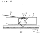
- FIG. 8 shows an essential part of a transducer-supporting structure in accordance with a fourth embodiment of the present invention.
- an optical pickup using a semiconductor laser which is an electro-optical transducer, is shown as a transducer.
- Reference numeral 30 denotes a disk
- 30a denotes a recording film produced by an existing phase change technology etc.
- Reference numeral 6 denotes a slider serving as a transducer mounting section. The slider 6 floats from the disk 30 by means of a lift of air flow caused by the relative movement of the disk 30 in the direction indicated by the arrow A to keep a predetermined distance.
- Reference numeral 8 denotes an integrated optical system serving as a transducer mounted on the slider 6.
- the integrated optical system 8 includes a semiconductor laser 8a and other optical elements such as a light intercepting element and a light separating element.
- Reference numeral 7 denotes an object lens mounted likewise on the slider 6.
- Reference numeral 33 denotes a suspension.
- the suspension 33 is connected to the slider 6, and applies a pressing force equal to the lift to the slider 6. Further, the semiconductor laser 8a is in direct contact with the suspension 33 together with the integrated optical system 8. Therefore, in this embodiment as in the case of the first embodiment, the suspension 33 is also used as a thermal coupling member.
- a beam emitted from the semiconductor laser 8a passes through the object lens 7 and is converged on the recording film 30a of the disk 30.
- the output of the semiconductor laser 8a is modulated according to information to be recorded, by which the modulated information is recorded on the recording film 30a.
- a servo signal is detected by receiving the return light reflected from the recording film 30a by using a light intercepting portion of the integrated optical system 8. The description of the case of reproducing operation is omitted because this operation is similar to the recording operation.
- the semiconductor laser 8a generates a large amount of heat relative to the volume thereof.
- the suspension 33 is connected to the semiconductor laser 8a, the heat can be dissipated through the suspension 33, so that a rise in temperature of the semiconductor laser 8 can be neglected.
- the life of the semiconductor laser 8a increases.
- a rise in temperature of the whole of the integrated optical system 8 can be prevented. Therefore, even in the case where an element whose shape is wavelength dependent such as a hologram element is used, the influence of thermal expansion can be neglected, so that the reliability and hostile-environment resistance are improved.
- a hologram element formed of a resin sensitive to thermal expansion can be used, which achieves a reduction in cost.
- the present invention is effectively applied to a transducer accompanied by heat generation regardless of the type of transducer.
- FIG. 9 shows an essential part of a transducer-supporting structure in accordance with a fifth embodiment of the present invention.
- a slider 1, a coil 4, and a disk 10 are the same as those elements of the first embodiment.
- the suspension is the same as the suspension 103 of the conventional example, and a gimbal portion 43b and a tongue 43c are the same as the gimbal portion 103b and the tongue 103c of the conventional example.
- a magnetic core 42 has the whole shape that is approximately the same as that of the magnetic core 4 of the first embodiment, but differs from the magnetic core 4 in that the magnetic core 42 has a heat dissipating portion 42b as heat dissipating means.
- first to third embodiments etc. can be applied as means of dissipating heat through the suspension and means of preventing the floating of the magnetic core 42.
- the heat dissipating portion 42a which is heat dissipating means, is provided integrally with the magnetic core 42 in this embodiment, the heat dissipating portion 42a can be formed of a separate part coupled thermally with the magnetic core 42.
- an electromagnetic transducer has been described as an example in this embodiment, the present invention can be applied effectively to other types of transducers, for example, an electro-optical transducer as described in the fourth embodiment and an electromechanical transducer such as a piezoelectric element.
- the heat of a transducer is dissipated through a suspension, by which a rise in temperature of the transducer and in the vicinity thereof can be restrained.
Landscapes
- Engineering & Computer Science (AREA)
- Manufacturing & Machinery (AREA)
- Supporting Of Heads In Record-Carrier Devices (AREA)
Abstract
Description
| [Explanation of reference numerals] | ||
| 1, 6 | | |
| 2, 42 | | |
| 3, 33 | | |
| 3d, 13d | thermally | |
| 15, 25 | heat conductive material | |
| | semiconductor laser | |
| 42b | heat dissipating portion |
Claims (13)
- A transducer-supporting structure, characterized in that said structure at least comprises:a transducer for recording and reproducing information on and from a medium;a transducer mounting section which is mounted with said transducer and comes into contact with said medium by means of mechanical action or keeps a fixed distance from said medium;a suspension which supports said transducer mounting section and elastically positions said transducer in the direction such as to bring and separate said transducer close to and from said medium; anda thermal coupling member for thermally coupling said transducer with said suspension, andheat generated in said transducer is dissipated through said suspension.
- The transducer-supporting structure according to claim 1, characterized in that said thermal coupling member has an elastic restoring force, and is in contact with said transducer.
- The transducer-supporting structure according to claim 1, characterized in that said thermal coupling member is formed of a part of said suspension.
- The transducer-supporting structure according to claim 1, characterized in that said thermal coupling member and said transducer or said thermal couplingmember and said suspension are partially coupled thermally with each other via a viscous fluid.
- The transducer-supporting structure according to claim 1, characterized in that said thermal coupling member is a gel-form substance, and said transducer and said suspension are coupled thermally with each other via said gel-form substance.
- The transducer-supporting structure according to claim 1, characterized in that said transducer is an electromagnetic transducer.
- The transducer-supporting structure according to claim 1, characterized in that said transducer is an electro-optical transducer.
- A transducer-supporting structure, characterized by at least comprising:a transducer for recording and reproducing information on and from a medium;heat dissipating means mounted on said transducer; anda suspension for holding said transducer at a desired position with respect to said recording medium.
- The transducer-supporting structure according to claim 8, characterized in that said heat dissipating means is formed integrally with said transducer.
- The transducer-supporting structure according to claim 8, characterized in that said transducer is an electromagnetic transducer.
- The transducer-supporting structure according to claim 8, characterized in that said transducer is an electro-optical transducer.
- A transducer-supporting structure, characterized in that said structure at least comprises:a transducer for recording and reproducing information on and from a medium;a transducer mounting section which is mounted with said transducer and comes into contact with said medium by means of mechanical action or keeps a fixed distance from said medium; anda suspension which is in direct contact with said transducer, supports said transducer mounting section, and elastically positions said transducer in the direction such as to bring and separate said transducer close to and from said medium, andheat generated in said transducer is dissipated through said suspension.
- The transducer-supporting structure according to claim 12, characterized in that heat generated in said transducer is transmitted to said suspension through said directly contacting portion, and is dissipated.
Applications Claiming Priority (3)
| Application Number | Priority Date | Filing Date | Title |
|---|---|---|---|
| JP13818499 | 1999-05-19 | ||
| JP13818499 | 1999-05-19 | ||
| PCT/JP2000/003152 WO2000072313A1 (en) | 1999-05-19 | 2000-05-17 | Converter support structure |
Publications (2)
| Publication Number | Publication Date |
|---|---|
| EP1193691A1 true EP1193691A1 (en) | 2002-04-03 |
| EP1193691A4 EP1193691A4 (en) | 2002-08-21 |
Family
ID=15216035
Family Applications (1)
| Application Number | Title | Priority Date | Filing Date |
|---|---|---|---|
| EP00927786A Withdrawn EP1193691A4 (en) | 1999-05-19 | 2000-05-17 | CONVERSION SUPPORT STRUCTURE |
Country Status (3)
| Country | Link |
|---|---|
| US (2) | US6731587B1 (en) |
| EP (1) | EP1193691A4 (en) |
| WO (1) | WO2000072313A1 (en) |
Families Citing this family (3)
| Publication number | Priority date | Publication date | Assignee | Title |
|---|---|---|---|---|
| US7159228B2 (en) * | 2001-12-12 | 2007-01-02 | Matsushita Electric Industrial Co., Ltd. | Converter support device with slider |
| US7433815B2 (en) | 2003-09-10 | 2008-10-07 | Dilithium Networks Pty Ltd. | Method and apparatus for voice transcoding between variable rate coders |
| JP4448736B2 (en) * | 2004-06-16 | 2010-04-14 | 株式会社日立メディアエレクトロニクス | Optical pickup device and optical disk device using the same |
Family Cites Families (22)
| Publication number | Priority date | Publication date | Assignee | Title |
|---|---|---|---|---|
| US4394530A (en) * | 1977-09-19 | 1983-07-19 | Kaufman Lance R | Power switching device having improved heat dissipation means |
| JPS5558822A (en) | 1978-10-23 | 1980-05-01 | Canon Inc | Magnetic head |
| US5114913A (en) * | 1988-02-12 | 1992-05-19 | International Business Machines Corporation | Magnetic head slider employing superconductor for levitation |
| JP2508955B2 (en) | 1992-04-20 | 1996-06-19 | ソニー株式会社 | Sliding magnetic head for magneto-optical recording |
| JP3158327B2 (en) | 1993-10-29 | 2001-04-23 | ソニー株式会社 | Magnetic head device for magneto-optical recording |
| JPH0863923A (en) * | 1994-08-25 | 1996-03-08 | Sony Corp | Magnetic head of magneto-optical recording device |
| JPH08138338A (en) * | 1994-09-14 | 1996-05-31 | Toshiba Corp | Magnetic disk unit |
| JPH08235556A (en) * | 1995-02-28 | 1996-09-13 | Sony Corp | Magnetic head device |
| US5808834A (en) * | 1995-06-07 | 1998-09-15 | Hutchinson Technology Incorporated | Laminated adapter |
| US5712748A (en) * | 1996-06-11 | 1998-01-27 | Seagate Technology, Inc. | Slider-suspension in a disc drive |
| US6009051A (en) * | 1996-10-14 | 1999-12-28 | Alps Electric Co., Ltd. | Magnetic head device |
| JPH10124802A (en) * | 1996-10-14 | 1998-05-15 | Alps Electric Co Ltd | Magnetic head device |
| JPH10283604A (en) * | 1997-04-08 | 1998-10-23 | Nippon Chemicon Corp | Magnetic field modulating head |
| US5968606A (en) * | 1997-06-30 | 1999-10-19 | Ferro Corporation | Screen printable UV curable conductive material composition |
| US5956211A (en) * | 1997-10-31 | 1999-09-21 | Questek Innovations, Inc. | Chip attached to actuator arm having heat conducting fibers |
| JPH11185231A (en) * | 1997-12-24 | 1999-07-09 | Tdk Corp | Magnetic head device |
| JPH11185233A (en) * | 1997-12-24 | 1999-07-09 | Tdk Corp | Magnetic head device |
| JP3257500B2 (en) * | 1998-02-27 | 2002-02-18 | ティーディーケイ株式会社 | Magnetic head device |
| US6021844A (en) * | 1998-06-03 | 2000-02-08 | Batchelder; John Samuel | Heat exchange apparatus |
| US6404706B1 (en) * | 1999-02-12 | 2002-06-11 | Read-Rite Corporation | Laser mounting for a thermally assisted GMR head |
| US6362966B1 (en) * | 1999-05-13 | 2002-03-26 | Intel Corporation | Protective cover and packaging for multi-chip memory modules |
| US6307719B1 (en) * | 1999-11-17 | 2001-10-23 | Maxtor Corporation | Suspension assembly with adjustable gramload |
-
2000
- 2000-05-17 EP EP00927786A patent/EP1193691A4/en not_active Withdrawn
- 2000-05-17 WO PCT/JP2000/003152 patent/WO2000072313A1/en not_active Ceased
- 2000-05-17 US US09/979,242 patent/US6731587B1/en not_active Expired - Fee Related
-
2004
- 2004-01-26 US US10/764,680 patent/US7013473B2/en not_active Expired - Fee Related
Also Published As
| Publication number | Publication date |
|---|---|
| EP1193691A4 (en) | 2002-08-21 |
| WO2000072313A1 (en) | 2000-11-30 |
| US6731587B1 (en) | 2004-05-04 |
| US7013473B2 (en) | 2006-03-14 |
| US20040158847A1 (en) | 2004-08-12 |
Similar Documents
| Publication | Publication Date | Title |
|---|---|---|
| US8102625B2 (en) | Magnetic head slider | |
| KR940022371A (en) | Integrated transducer for vertical recording-suspension assembly | |
| US6507540B1 (en) | Hybrid optical head for data storage | |
| JPH0863824A (en) | Magnetic head for magneto-optical recording, manufacturing method thereof, and magneto-optical recording device | |
| US7013473B2 (en) | Transducer-supporting structure | |
| GB2181879A (en) | Magneto-optical information recording apparatus | |
| JP5469484B2 (en) | Near-field light utilizing head gimbal assembly and information recording / reproducing apparatus including the same | |
| US5703840A (en) | Magnetic head and magneto-optical recording device | |
| JP2001035108A (en) | Converter support structure | |
| JP3030968B2 (en) | Magnetic head for magneto-optical recording | |
| US7159228B2 (en) | Converter support device with slider | |
| JPH08235556A (en) | Magnetic head device | |
| US20020154445A1 (en) | Suspension and head gimbal assembly | |
| JPH09185835A (en) | Optical pickup device | |
| KR100587440B1 (en) | An object lens drive unit and an optical disk device | |
| JP2000090403A (en) | Magnetic head for magneto-optical recording and magneto-optical recording device | |
| JPH02294903A (en) | Magnetic head | |
| JP2002150633A (en) | Magnetic head device | |
| JP3549793B2 (en) | Magnetic head support mechanism | |
| JP2001056902A (en) | Magnetic head | |
| JP2923384B2 (en) | Magnetic head | |
| JPH04102202A (en) | Magnetic field generator for magneto-optical recording | |
| JP2003242735A (en) | Transducer support device | |
| JP5592121B2 (en) | Near-field light utilizing head gimbal assembly and information recording / reproducing apparatus including the same | |
| JP2624162B2 (en) | Sliding magnetic head device |
Legal Events
| Date | Code | Title | Description |
|---|---|---|---|
| PUAI | Public reference made under article 153(3) epc to a published international application that has entered the european phase |
Free format text: ORIGINAL CODE: 0009012 |
|
| 17P | Request for examination filed |
Effective date: 20011119 |
|
| AK | Designated contracting states |
Kind code of ref document: A1 Designated state(s): AT BE CH CY DE DK ES FI FR GB GR IE IT LI LU MC NL PT SE Kind code of ref document: A1 Designated state(s): DE FR GB |
|
| AX | Request for extension of the european patent |
Free format text: AL;LT;LV;MK;RO;SI |
|
| A4 | Supplementary search report drawn up and despatched |
Effective date: 20020704 |
|
| AK | Designated contracting states |
Kind code of ref document: A4 Designated state(s): AT BE CH CY DE DK ES FI FR GB GR IE IT LI LU MC NL PT SE |
|
| RIC1 | Information provided on ipc code assigned before grant |
Free format text: 7G 11B 11/105 A, 7G 11B 21/21 B, 7G 11B 5/40 B, 7G 11B 5/48 B |
|
| RIN1 | Information on inventor provided before grant (corrected) |
Inventor name: ENSHU, HIROYASU Inventor name: MURAKAMI, YUTAKA Inventor name: AIKOH, HIDEKI Inventor name: NAKAMURA, TOHRU Inventor name: MIZUNO, OSAMU |
|
| RBV | Designated contracting states (corrected) |
Designated state(s): DE FR GB |
|
| 17Q | First examination report despatched |
Effective date: 20050627 |
|
| RAP1 | Party data changed (applicant data changed or rights of an application transferred) |
Owner name: PANASONIC CORPORATION |
|
| STAA | Information on the status of an ep patent application or granted ep patent |
Free format text: STATUS: THE APPLICATION IS DEEMED TO BE WITHDRAWN |
|
| 18D | Application deemed to be withdrawn |
Effective date: 20080716 |