EP1193520A2 - Operationsmikroskop - Google Patents
Operationsmikroskop Download PDFInfo
- Publication number
- EP1193520A2 EP1193520A2 EP01120854A EP01120854A EP1193520A2 EP 1193520 A2 EP1193520 A2 EP 1193520A2 EP 01120854 A EP01120854 A EP 01120854A EP 01120854 A EP01120854 A EP 01120854A EP 1193520 A2 EP1193520 A2 EP 1193520A2
- Authority
- EP
- European Patent Office
- Prior art keywords
- surgical microscope
- image sensor
- image
- imaging
- objective
- Prior art date
- Legal status (The legal status is an assumption and is not a legal conclusion. Google has not performed a legal analysis and makes no representation as to the accuracy of the status listed.)
- Granted
Links
- 238000001514 detection method Methods 0.000 claims abstract description 4
- 238000003384 imaging method Methods 0.000 claims description 9
- 238000011156 evaluation Methods 0.000 claims description 5
- 230000003287 optical effect Effects 0.000 claims description 3
- 238000003491 array Methods 0.000 description 1
- 230000001419 dependent effect Effects 0.000 description 1
- 239000003550 marker Substances 0.000 description 1
- 238000005259 measurement Methods 0.000 description 1
Images
Classifications
-
- G—PHYSICS
- G02—OPTICS
- G02B—OPTICAL ELEMENTS, SYSTEMS OR APPARATUS
- G02B21/00—Microscopes
- G02B21/0004—Microscopes specially adapted for specific applications
- G02B21/0012—Surgical microscopes
-
- A—HUMAN NECESSITIES
- A61—MEDICAL OR VETERINARY SCIENCE; HYGIENE
- A61B—DIAGNOSIS; SURGERY; IDENTIFICATION
- A61B90/00—Instruments, implements or accessories specially adapted for surgery or diagnosis and not covered by any of the groups A61B1/00 - A61B50/00, e.g. for luxation treatment or for protecting wound edges
- A61B90/20—Surgical microscopes characterised by non-optical aspects
Definitions
- the invention relates to a surgical microscope according to the preamble of claim 1.
- Such a surgical microscope is known for example from US 5,999,837.
- This Known surgical microscope can position and position of an object in the field of view Surgical microscope relative to the surgical microscope by detecting the position of the Surgical microscope relative to the operating room and by detecting the position of the corresponding object relative to the operating room, for example with the aid of a pointer be determined.
- the object of the invention is to provide a generic surgical microscope with which carried out the position and position detection easier, more precise and less prone to failure can be.
- the position and position detection can be done directly from the two Image sensors recorded stereo image pairs by, for example, from DE 37 20 019 C2 known evaluation method. This allows location and position relative to the Surgical microscope with a smaller number of measurements than previously recorded.
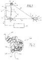
- a surgical microscope 1 according to the invention is shown schematically in FIG.
- a surgical instrument 2 which as spherical reflectors trained markers 3, 4, 5, 6, 7, 8 and 9.
- the surgical microscope 1 comprises an objective 12, eyepieces 14 and 16 and next to it Objective 12 arranged image sensors 10 and 11, which for example as CCD arrays can be trained.
- the two image sensors 10 and 11 are for generation Coordinate evaluable stereo image pairs at a distance from each other and with different orientation to each other.
- the surgical microscope 1 further comprises camera lenses Imaging devices 13 and 15, which the objects in the field of view of the surgical microscope 1 and z. B. in particular the markers 3, 4, 5, 6, 7, 8 and 9 of the surgical instrument 2 on the Show image sensors 10 and 11, respectively. With 29 and 31 are the optical axes of the image sensors 10 or 11 designated. Also at 33 and 35, respectively, is the main beam for the marker 7 on the image sensor 10 or 11 contributing bundle of rays.
- the images captured by the image sensors 10 and 11 are sent to a signal line 19 Transfer evaluation unit 21 which, from these images, the location coordinates of the markers 3, 4, 5, 6, 7, 8 and 9 in a by the arrangement of the image sensors 10 and 11 and thereby determined coordinate system related to the surgical microscope 1.
- the surgical microscope according to the invention can also have three or even more image sensors be equipped, where then instead of a pair of images, a triple image, etc. from the Evaluation unit 21 is to be evaluated.
- FIG. 1 A surgical microscope according to the invention is shown in a perspective view in FIG Recognizable representation.
- Elements Corresponding to the elements of the surgical microscope 1 in FIG. 1 Elements have the same reference numbers, increased by the number 100. For their description reference is made to the description of FIG. 1.
Landscapes
- Health & Medical Sciences (AREA)
- Surgery (AREA)
- Physics & Mathematics (AREA)
- General Health & Medical Sciences (AREA)
- Life Sciences & Earth Sciences (AREA)
- Pathology (AREA)
- Engineering & Computer Science (AREA)
- Optics & Photonics (AREA)
- Nuclear Medicine, Radiotherapy & Molecular Imaging (AREA)
- Oral & Maxillofacial Surgery (AREA)
- Analytical Chemistry (AREA)
- Chemical & Material Sciences (AREA)
- General Physics & Mathematics (AREA)
- Biomedical Technology (AREA)
- Heart & Thoracic Surgery (AREA)
- Medical Informatics (AREA)
- Molecular Biology (AREA)
- Animal Behavior & Ethology (AREA)
- Public Health (AREA)
- Veterinary Medicine (AREA)
- Microscoopes, Condenser (AREA)
Abstract
Description
- Figur 1:
- eine schematische Darstellung einer Ausführungsform der Erfindung; und
- Figur 2:
- eine perspektivische Ansicht eines derartigen Operationsmikroskops.
Claims (4)
- Operationsmikroskop (1; 101) mit einem Objektiv(12; 112) zur Beobachtung eines Objekts und mit einer Vorrichtung zur Positions- und Lageerfassung von Objektpunkten,
dadurch gekennzeichnet, daß
das Operationsmikroskop (1; 101) einen ersten Bildsensor (10) und einen zweiten Bildsensor (11) umfaßt, welche in Abstand voneinander angeordnet sind. - Operationsmikroskop (1, 101) nach Anspruch 1, wobei das Operationsmikroskop (1, 101) eine das Objekt auf den ersten Bildsensor (10) abbildende Abbildungseinrichtung (13) und eine das Objekt auf den zweiten Bildsensor (11) abbildende Abbildungseinrichtung (15) umfaßt, deren optische Achsen (29, 31) schräg zur optischen Achse (18) des Objektives (12) verlaufen.
- Operationsmikroskop (1; 101) nach Anspruch 2, wobei die Abbildungseinrichtungen (13, 15; 113, 115) beidseits des Objektives (12; 112) angeordnet sind.
- Operationsmikroskop (1; 101) nach einem der Ansprüche 1 bis 3, wobei eine Auswerteeinheit (21) aus dem Ort eines Objektpunkts in dem von dem ersten Bildsensor (10) erfaßten Bild und aus seinem Ort in dem von dem zweiten Bildsensor (11) erfaßten Bild sowie aus der räumlichen Anordnung der Bildsensoren (10, 11) und der Abbildungseinrichtungen (13, 15; 113, 115) Lage und Position des Objektpunkts relativ zum Operationsmikroskop (1; 101) bestimmt.
Applications Claiming Priority (2)
| Application Number | Priority Date | Filing Date | Title |
|---|---|---|---|
| DE10048546A DE10048546A1 (de) | 2000-09-30 | 2000-09-30 | Operationsmikroskop |
| DE10048546 | 2000-09-30 |
Publications (4)
| Publication Number | Publication Date |
|---|---|
| EP1193520A2 true EP1193520A2 (de) | 2002-04-03 |
| EP1193520A3 EP1193520A3 (de) | 2003-08-27 |
| EP1193520B1 EP1193520B1 (de) | 2006-01-18 |
| EP1193520B8 EP1193520B8 (de) | 2006-05-03 |
Family
ID=7658260
Family Applications (1)
| Application Number | Title | Priority Date | Filing Date |
|---|---|---|---|
| EP01120854A Expired - Lifetime EP1193520B8 (de) | 2000-09-30 | 2001-08-30 | Operationsmikroskop |
Country Status (4)
| Country | Link |
|---|---|
| US (1) | US20020040190A1 (de) |
| EP (1) | EP1193520B8 (de) |
| JP (1) | JP4102047B2 (de) |
| DE (2) | DE10048546A1 (de) |
Cited By (1)
| Publication number | Priority date | Publication date | Assignee | Title |
|---|---|---|---|---|
| DE102018206406B3 (de) | 2018-04-25 | 2019-09-12 | Carl Zeiss Meditec Ag | Mikroskopiesystem und Verfahren zum Betrieb eines Mikroskopiesystems |
Families Citing this family (3)
| Publication number | Priority date | Publication date | Assignee | Title |
|---|---|---|---|---|
| DE102009037921B4 (de) * | 2009-08-19 | 2014-02-13 | Carl Zeiss Meditec Ag | Tubus für Operationsmikroskop |
| DE102010003836B4 (de) | 2010-04-09 | 2013-11-21 | Leica Microsystems (Schweiz) Ag | Mikroskopgerät und Mikroskopieverfahren |
| DE102021202951A1 (de) * | 2021-03-25 | 2022-09-29 | Carl Zeiss Meditec Ag | Medizinisches Gerät zur Ermittlung der räumlichen Lage eines flächig ausgebildeten Markers |
Family Cites Families (5)
| Publication number | Priority date | Publication date | Assignee | Title |
|---|---|---|---|---|
| US5662111A (en) * | 1991-01-28 | 1997-09-02 | Cosman; Eric R. | Process of stereotactic optical navigation |
| DE4134481C2 (de) * | 1991-10-18 | 1998-04-09 | Zeiss Carl Fa | Operationsmikroskop zur rechnergestützten, stereotaktischen Mikrochirurgie |
| US5579772A (en) * | 1993-06-14 | 1996-12-03 | Olympus Optical Co., Ltd. | Surgical microscope system |
| US5999837A (en) * | 1997-09-26 | 1999-12-07 | Picker International, Inc. | Localizing and orienting probe for view devices |
| JP4101951B2 (ja) * | 1998-11-10 | 2008-06-18 | オリンパス株式会社 | 手術用顕微鏡 |
-
2000
- 2000-09-30 DE DE10048546A patent/DE10048546A1/de not_active Withdrawn
-
2001
- 2001-08-30 EP EP01120854A patent/EP1193520B8/de not_active Expired - Lifetime
- 2001-08-30 DE DE50108733T patent/DE50108733D1/de not_active Expired - Lifetime
- 2001-09-28 US US09/964,429 patent/US20020040190A1/en not_active Abandoned
- 2001-10-01 JP JP2001304894A patent/JP4102047B2/ja not_active Expired - Lifetime
Cited By (1)
| Publication number | Priority date | Publication date | Assignee | Title |
|---|---|---|---|---|
| DE102018206406B3 (de) | 2018-04-25 | 2019-09-12 | Carl Zeiss Meditec Ag | Mikroskopiesystem und Verfahren zum Betrieb eines Mikroskopiesystems |
Also Published As
| Publication number | Publication date |
|---|---|
| EP1193520B8 (de) | 2006-05-03 |
| EP1193520A3 (de) | 2003-08-27 |
| EP1193520B1 (de) | 2006-01-18 |
| JP2002191616A (ja) | 2002-07-09 |
| JP4102047B2 (ja) | 2008-06-18 |
| US20020040190A1 (en) | 2002-04-04 |
| DE10048546A1 (de) | 2002-04-11 |
| DE50108733D1 (de) | 2006-04-06 |
Similar Documents
| Publication | Publication Date | Title |
|---|---|---|
| EP3076148B1 (de) | Vorrichtung und verfahren zum messen von abbildungseigenschaften eines optischen abbildungssystems | |
| EP3410091B1 (de) | Verfahren zum erfassen einer modulations-transferfunktion und einer zentrierung eines optischen systems | |
| EP1404545B1 (de) | Vorrichtung zur bilddetektion von gegenständen, personen oder dergleichen im umfeld eines fahrzeuges | |
| EP3166312A1 (de) | Vorrichtung und verfahren zum justieren und/oder kalibrieren eines multi-kamera moduls sowie verwendung einer solchen vorrichtung | |
| EP3602624B1 (de) | Verfahren zur ausrichtung zweier substrate | |
| DE10137241A1 (de) | Registrierung von Tiefenbildern mittels optisch projizierter Marken | |
| DE10308383A1 (de) | Verfahren und optisches System zur Vermessung der Topographie eines Meßobjekts | |
| EP1184640A2 (de) | Fahrwerkvermessungseinrichtung | |
| DE112008002467T5 (de) | Verfahren für die Entnahme von Halbleiterchips von einem Wafertisch und Verfahren für die Montage von Halbleiterchips auf einem Substrat | |
| EP2166510A1 (de) | Verfahren zum Ermitteln der Position und der Orientierung einer in einem Fahrzeug angeordneten Kamera | |
| EP2506027B1 (de) | Abbildungssystem für Sternsensoren mit zwei Brennweiten | |
| EP2133659A1 (de) | Verfahren und Vorrichtung zur Ermittlung der Lage eines Sensors | |
| DE102017011177A1 (de) | Verfahren zum Ermitteln eines Knickwinkels eines Fahrzeug-Gespanns, Ermittlungseinrichtung sowie Fahrzeug-Gespann | |
| DE102018127221A1 (de) | Koordinatenmesssystem | |
| DE102008000837A1 (de) | Fahrwerksvermessungssystem sowie Verfahren zum Bestimmen der Lageparameter von Messköpfen eines Fahrwerksvermessungssystems | |
| WO2009018894A1 (de) | Verfahren und vorrichtung zum bestimmen von geometriedaten eines messobjekts | |
| EP1193520B1 (de) | Operationsmikroskop | |
| DE102010031056A1 (de) | Verfahren zum Kalibrieren eines Messsystems und eines Messplatzes zur Fahrzeugvermessung | |
| DE2832173A1 (de) | Stereoskopisches mikroskop | |
| DE102019100303A1 (de) | Verfahren und Vorrichtung zum Ermitteln einer Krümmung einer Fahrbahn | |
| DE102007021107B4 (de) | Vorrichtung und Verfahren zum Bestimmen des Hauptpunktes eines Kamerasystems | |
| DE102011112150A1 (de) | Verfahren zur Bestimmung eines Ausmaßes eines Objekts in einer Umgebung eines Fahrzeugs sowie eine entsprechende Vorrichtung und ein Fahrzeug mit einer derartigen Vorrichtung. | |
| DE102020107181A1 (de) | Verfahren und Vorrichtung zum Orten von Schallquellen durch Beamforming | |
| DE19841394A1 (de) | Vorrichtung zur Positions- und Lageerfassung mit passiven Markern | |
| DE10048095A1 (de) | Verfahren zur Korrektur einer Dreh-Schwenkeinheit |
Legal Events
| Date | Code | Title | Description |
|---|---|---|---|
| PUAI | Public reference made under article 153(3) epc to a published international application that has entered the european phase |
Free format text: ORIGINAL CODE: 0009012 |
|
| AK | Designated contracting states |
Kind code of ref document: A2 Designated state(s): AT BE CH CY DE DK ES FI FR GB GR IE IT LI LU MC NL PT SE TR |
|
| AX | Request for extension of the european patent |
Free format text: AL;LT;LV;MK;RO;SI |
|
| PUAL | Search report despatched |
Free format text: ORIGINAL CODE: 0009013 |
|
| AK | Designated contracting states |
Designated state(s): AT BE CH CY DE DK ES FI FR GB GR IE IT LI LU MC NL PT SE TR |
|
| AX | Request for extension of the european patent |
Extension state: AL LT LV MK RO SI |
|
| 17P | Request for examination filed |
Effective date: 20040213 |
|
| AKX | Designation fees paid |
Designated state(s): CH DE FR GB LI |
|
| 17Q | First examination report despatched |
Effective date: 20040504 |
|
| RAP1 | Party data changed (applicant data changed or rights of an application transferred) |
Owner name: CARL-ZEISS-STIFTUNG TRADING AS CARL ZEISS Owner name: CARL ZEISS |
|
| GRAJ | Information related to disapproval of communication of intention to grant by the applicant or resumption of examination proceedings by the epo deleted |
Free format text: ORIGINAL CODE: EPIDOSDIGR1 |
|
| GRAP | Despatch of communication of intention to grant a patent |
Free format text: ORIGINAL CODE: EPIDOSNIGR1 |
|
| GRAP | Despatch of communication of intention to grant a patent |
Free format text: ORIGINAL CODE: EPIDOSNIGR1 |
|
| RAP1 | Party data changed (applicant data changed or rights of an application transferred) |
Owner name: CARL-ZEISS-STIFTUNG, TRADING AS CARL ZEISS Owner name: CARL ZEISS |
|
| GRAS | Grant fee paid |
Free format text: ORIGINAL CODE: EPIDOSNIGR3 |
|
| GRAA | (expected) grant |
Free format text: ORIGINAL CODE: 0009210 |
|
| RAP1 | Party data changed (applicant data changed or rights of an application transferred) |
Owner name: CARL-ZEISS-STIFTUNG, TRADING AS CARL ZEISS Owner name: CARL ZEISS SURGICAL GMBH |
|
| AK | Designated contracting states |
Kind code of ref document: B1 Designated state(s): CH DE FR GB LI |
|
| REG | Reference to a national code |
Ref country code: GB Ref legal event code: FG4D Free format text: NOT ENGLISH |
|
| RIN1 | Information on inventor provided before grant (corrected) |
Inventor name: QUENDT, DIETER Inventor name: DUEVER, ERIK Inventor name: GOLD, ULRICH Inventor name: DUSCHEK, CHRISTIAN Inventor name: PELZER, MARTIN Inventor name: NAEGELE, ULRICH |
|
| REG | Reference to a national code |
Ref country code: CH Ref legal event code: EP |
|
| RAP2 | Party data changed (patent owner data changed or rights of a patent transferred) |
Owner name: CARL-ZEISS-STIFTUNG, TRADING AS CARL ZEISS Owner name: CARL ZEISS SURGICAL GMBH |
|
| RAP2 | Party data changed (patent owner data changed or rights of a patent transferred) |
Owner name: CARL ZEISS SURGICAL GMBH |
|
| REF | Corresponds to: |
Ref document number: 50108733 Country of ref document: DE Date of ref document: 20060406 Kind code of ref document: P |
|
| GBT | Gb: translation of ep patent filed (gb section 77(6)(a)/1977) |
Effective date: 20060628 |
|
| ET | Fr: translation filed | ||
| PLBE | No opposition filed within time limit |
Free format text: ORIGINAL CODE: 0009261 |
|
| STAA | Information on the status of an ep patent application or granted ep patent |
Free format text: STATUS: NO OPPOSITION FILED WITHIN TIME LIMIT |
|
| 26N | No opposition filed |
Effective date: 20061019 |
|
| REG | Reference to a national code |
Ref country code: FR Ref legal event code: PLFP Year of fee payment: 15 |
|
| REG | Reference to a national code |
Ref country code: FR Ref legal event code: PLFP Year of fee payment: 16 |
|
| REG | Reference to a national code |
Ref country code: FR Ref legal event code: PLFP Year of fee payment: 17 |
|
| REG | Reference to a national code |
Ref country code: FR Ref legal event code: PLFP Year of fee payment: 18 |
|
| PGFP | Annual fee paid to national office [announced via postgrant information from national office to epo] |
Ref country code: DE Payment date: 20200819 Year of fee payment: 20 Ref country code: GB Payment date: 20200826 Year of fee payment: 20 Ref country code: FR Payment date: 20200821 Year of fee payment: 20 |
|
| PGFP | Annual fee paid to national office [announced via postgrant information from national office to epo] |
Ref country code: CH Payment date: 20200819 Year of fee payment: 20 |
|
| REG | Reference to a national code |
Ref country code: DE Ref legal event code: R071 Ref document number: 50108733 Country of ref document: DE |
|
| REG | Reference to a national code |
Ref country code: CH Ref legal event code: PL |
|
| REG | Reference to a national code |
Ref country code: GB Ref legal event code: PE20 Expiry date: 20210829 |
|
| PG25 | Lapsed in a contracting state [announced via postgrant information from national office to epo] |
Ref country code: GB Free format text: LAPSE BECAUSE OF EXPIRATION OF PROTECTION Effective date: 20210829 |