EP1193201A1 - Method and device for forming a double shingled formation of printed products - Google Patents
Method and device for forming a double shingled formation of printed products Download PDFInfo
- Publication number
- EP1193201A1 EP1193201A1 EP01120926A EP01120926A EP1193201A1 EP 1193201 A1 EP1193201 A1 EP 1193201A1 EP 01120926 A EP01120926 A EP 01120926A EP 01120926 A EP01120926 A EP 01120926A EP 1193201 A1 EP1193201 A1 EP 1193201A1
- Authority
- EP
- European Patent Office
- Prior art keywords
- conveyor
- printed products
- transfer
- conveying
- printed
- Prior art date
- Legal status (The legal status is an assumption and is not a legal conclusion. Google has not performed a legal analysis and makes no representation as to the accuracy of the status listed.)
- Granted
Links
Images

Classifications
-
- B—PERFORMING OPERATIONS; TRANSPORTING
- B65—CONVEYING; PACKING; STORING; HANDLING THIN OR FILAMENTARY MATERIAL
- B65H—HANDLING THIN OR FILAMENTARY MATERIAL, e.g. SHEETS, WEBS, CABLES
- B65H29/00—Delivering or advancing articles from machines; Advancing articles to or into piles
- B65H29/66—Advancing articles in overlapping streams
- B65H29/6609—Advancing articles in overlapping streams forming an overlapping stream
-
- B—PERFORMING OPERATIONS; TRANSPORTING
- B65—CONVEYING; PACKING; STORING; HANDLING THIN OR FILAMENTARY MATERIAL
- B65H—HANDLING THIN OR FILAMENTARY MATERIAL, e.g. SHEETS, WEBS, CABLES
- B65H2301/00—Handling processes for sheets or webs
- B65H2301/40—Type of handling process
- B65H2301/44—Moving, forwarding, guiding material
- B65H2301/444—Stream of articles in shingled formation, overlapping stream
- B65H2301/4447—Stream of articles in shingled formation, overlapping stream multiple streams
- B65H2301/44472—Stream of articles in shingled formation, overlapping stream multiple streams superposed
-
- B—PERFORMING OPERATIONS; TRANSPORTING
- B65—CONVEYING; PACKING; STORING; HANDLING THIN OR FILAMENTARY MATERIAL
- B65H—HANDLING THIN OR FILAMENTARY MATERIAL, e.g. SHEETS, WEBS, CABLES
- B65H2301/00—Handling processes for sheets or webs
- B65H2301/40—Type of handling process
- B65H2301/44—Moving, forwarding, guiding material
- B65H2301/447—Moving, forwarding, guiding material transferring material between transport devices
- B65H2301/4471—Grippers, e.g. moved in paths enclosing an area
-
- B—PERFORMING OPERATIONS; TRANSPORTING
- B65—CONVEYING; PACKING; STORING; HANDLING THIN OR FILAMENTARY MATERIAL
- B65H—HANDLING THIN OR FILAMENTARY MATERIAL, e.g. SHEETS, WEBS, CABLES
- B65H2301/00—Handling processes for sheets or webs
- B65H2301/40—Type of handling process
- B65H2301/44—Moving, forwarding, guiding material
- B65H2301/447—Moving, forwarding, guiding material transferring material between transport devices
- B65H2301/4473—Belts, endless moving elements on which the material is in surface contact
- B65H2301/44732—Belts, endless moving elements on which the material is in surface contact transporting articles in overlapping stream
Abstract
Description
Die Erfindung betrifft ein Verfahren zur Bildung eines
Schuppenstroms aus ersten und zweiten Druckereiprodukten,
bei dem jeweils ein erstes und ein zweites Druckereiprodukt
weitgehend deckungsgleich aufeinander liegen
(Doppelschuppenformation) nach Anspruch 1 sowie eine
Vorrichtung zur Durchführung des Verfahrens nach Anspruch
8. Die Erfindung betrifft weiterhin Vorrichtung zum Bilden
und Wegförderen eines Schuppenstroms aus Druckereiprodukten
an wahlweise einem ersten Übergabebereich oder
einem stromabwärts hinter dem ersten Übergabebereich
liegenden zweiten ÜbergabebereichThe invention relates to a method for forming a
Scale flow from first and second printed products,
in each of which a first and a second printed product
are largely congruent with each other
(Double scale formation) according to
Druckereiprodukte, z.B. Zeitungen, Zeitschriften, Magazine, Faltblätter und dergleichen, werden während der Herstellung häufig in einer sogenannten Schuppenanordnung von einer Verarbeitungsstation zur nächsten befördert. Bei einer Schuppenanordnung überlappt ein Druckereiprodukt das darunter liegende, in Förderrichtung weiter vorne befindliche Druckereiprodukt teilweise, wobei die in Förderrichtung seitlichen Kanten der Druckereiprodukte im wesentlichen bündig miteinander abschliessen. Bei gefalteten Druckereiprodukten unterscheidet man eine Vorwärts-Schuppenanordnung, bei der die gefaltete Kante eines jeden Druckereiprodukts in Förderrichtung vorne liegt, von einer Rückwärts-Schuppenanordnung, bei der der Falz in Förderrichtung hinten liegt. Die Falzkante kann dabei oben oder unten liegen. Schuppenanordnungen werden beispielsweise gebildet, indem Druckereiprodukte aus einer Bearbeitungstrommel oder von einem Druckereiproduktstapel einzeln ergriffen und in regelmässigen zeitlichen Abständen auf ein Förderband eines Wegförderers abgelegt werden, das sich kontinuierlich mit einer vorgegebenen Geschwindigkeit bewegt. Das Ergreifen von einzelnen Druckereiprodukten, die aus einer Bearbeitungstrommel kommen, durch in regelmässigen Abständen angeordnete Greifer eines Zwischenförderers ist beispielsweise in der EP-A 0 686 463 oder EP-A 0 753 386 gezeigt.Printed products, e.g. Newspapers, magazines, Magazines, leaflets, and the like are used during the Often manufactured in a so-called scale arrangement transported from one processing station to the next. at a printed product overlaps a scale arrangement underlying, further forward in the conveying direction located printing product partially, the in Direction of conveyance lateral edges of the printed products in the close essentially flush with each other. at folded printed products can be distinguished Forward shingled arrangement with the folded edge of each printed product in the conveying direction at the front is from a backward scale arrangement in which the Fold lies at the back in the conveying direction. The fold edge can lie above or below. Scale arrangements will be for example, formed by printing products from a Processing drum or from a stack of printed products seized individually and in regular time Clearances placed on a conveyor belt of a conveyor be that continuously with a predetermined Speed moves. Grasping individuals Printing products made from a processing drum come, by arranged at regular intervals The gripper of an intermediate conveyor is, for example, in the EP-A 0 686 463 or EP-A 0 753 386.
Für einige Anwendungen ist es wünschenswert, die Druckereiprodukte nicht in regelmässigen Abständen voneinander zu fördern, wobei jedes Druckereiprodukt nur teilweise mit seinem Vorgänger und mit seinem Nachfolger überlappt (Einfachschuppenformation), sondern als Doppel-oder Mehrfachschuppenformation zu kleinen Gruppen zusammengefasst. Jeweils zwei oder mehr Druckereiprodukte sollen dabei einander weitgehend überlappen, z.B. indem sie weitgehend deckungsgleich aufeinander gelegt werden. Eine Gruppe überlappt dann die folgende Gruppe aus Druckereiprodukten wiederum nur teilweise.For some applications it is desirable that Print products not at regular intervals to promote each other, with each print product only partly with his predecessor and with his successor overlaps (single scale formation), but as a double or Multiple scale formation to small groups summarized. Two or more printed products each should largely overlap one another, e.g. by doing they are largely superimposed on one another. One group then overlaps the following group Printed products, in turn, only partially.
Der Erfindung liegt die Aufgabe zugrunde, ein Verfahren und eine Vorrichtung zur Bildung eines Schuppenstroms aus Gruppen von Druckereiprodukten anzugeben. Insbesondere soll ein Verfahren und eine Vorrichtung zur Bildung eines Doppelschuppenstroms, bei dem eine solche Gruppe zwei Druckereiprodukte umfasst, angegeben werden.The invention has for its object a method and a device for forming a shingled stream Specify groups of printed products. In particular is intended to be a method and an apparatus for forming a Double scale flow, in which such a group two Printed products includes to be specified.
Der Erfindung liegt weiterhin die Aufgabe zugrunde, eine bekannte Vorrichtung zur Bildung eines Schuppenstroms so weiterzuentwickeln, dass eine höhere Flexibilität bezüglich der Transportrichtung und der Art der weggeförderten Schuppenformation erreichbar ist. The invention is also based on the object known device for forming a stream of shingles further develop that greater flexibility regarding the direction of transport and the type of removed scale formation is accessible.
Die Aufgabe wird gelöst durch ein Verfahren zur Bildung
eines Schuppennstroms aus ersten und zweiten
Druckereiprodukten in einer Doppelschuppenformation mit
den Merkmalen des Anspruchs 1. Die Aufgabe wird weiterhin
gelöst durch eine Vorrichtung zur Durchführung des
Verfahrens mit den Merkmalen von Anspruch 8. Die
Flexibilität von Transportvorrichtungen wird erhöht mit
einer Vorrichtung mit den Merkmalen des Anspruchs 18.
Vorteilhafte Weiterbildungen des Verfahrens und der
Vorrichtungen ergeben sich aus den abhängigen Ansprüchen,
der nachfolgenden Beschreibung und den Zeichnungen.The task is solved by a method of education
a shingled stream of first and second
Printing products in a double scale formation with
the features of
Erfindungsgemäss werden erste und zweite Druckereiprodukte abwechselnd einzeln von einem Zwischenförderer ergriffen und auf ein Förderband eines Wegförderers abgelegt, wobei jeweils ein zweites Druckereiprodukt dem Wegförderer so zugeführt wird, dass es weitgehend deckungsgleich, d.h. mit maximalem Überlapp, auf einem ersten, bereits auf dem Wegförderer abgelegten und das vorhergehende Druckereiprodukt schuppenartig überlappenden Druckereiprodukt zu liegen kommt. Als "erstes" Druckereiprodukt wird im Folgenden jeweils das zuerst abgelegte Druckereiprodukt bezeichnet, das in einer Gruppe von Druckereiprodukten zuunterst liegt. Als "zweites" Druckereiprodukt wird jenes bezeichnet, das mit maximalem Überlapp auf dem ersten Druckereiprodukt aufliegt. Erste und zweite Druckereiprodukte können, aber müssen nicht, unterschiedlich sein. Sie sind beispielsweise unterschiedlich, wenn verschiedene Vorprodukte zur Herstellung eines Hauptprodukts gruppiert werden sollen, und gleich, wenn lediglich eine Weiterverarbeitung von Stapeln gefordert ist.According to the invention, first and second printed products alternately seized individually by an intermediate conveyor and placed on a conveyor belt of a conveyor, wherein a second printed product to the conveyor that it is largely congruent, i.e. with maximum overlap, on a first, already on the Removed conveyor and the previous print product scale-like overlapping printed product comes to lie. The "first" print product is in The following is the first printed product to be stored referred to that in a group of printed products is at the bottom. The "second" printed product is that designated that with maximum overlap on the first Printed product rests. First and second print products can, but need not, be different. For example, they are different when different Intermediates for the production of a main product grouped should be, and immediately, if only further processing of stacks.
Als Zwischenförderer kommt vorzugsweise ein Greiferförderer mit in Förderrichtung hintereinander angeordneten Greifern zum Einsatz. Als "erste" Greifer werden die Greifer bezeichnet, die ein erstes Druckereiprodukt erfassen, als "zweite" Greifer solche für die Aufnahme eines zweiten Druckereiprodukts. Erste und zweite Greifer können baulich identisch sein. Erfindungsgemäss wechseln sich erste Greifer mit davon erfassten ersten Druckereiprodukten mit zweiten Greifern mit davon erfassten zweiten Druckereiprodukten ab. Soll eine Schuppenformation mit mehr als zwei Druckereiprodukten pro Gruppe gebildet werden, so werden entsprechend noch "dritte", "vierte" usw. Druckereiprodukte auf das erste und zweite Druckereiprodukt aufgelegt.A gripper conveyor is preferably used as the intermediate conveyor with one behind the other in the conveying direction Grippers for use. The "first" grippers are Gripper, which is a first printed product capture as a "second" gripper such for inclusion of a second printed product. First and second grippers can be structurally identical. Change according to the invention first gripper with the first grasped by it Printed products with second grippers with them captured second printing products. Should one Scale formation with more than two printed products per Group are formed, so will still be "third", "fourth" etc. printing products on the first and second printed product.
Erfindungsgemäss werden die ersten und zweiten Druckereiprodukte, die beispielsweise aus einer Bearbeitungstrommel oder von einem Druckereiproduktstapel kommen, einzeln und hintereinander vom Zwischenförderer erfasst, der mit einer Fördergeschwindigkeit v1 fördert. In diesem Verfahrensschritt wird daher ein Strom aus Druckereiprodukten gebildet, die voneinander etwa den gleichen Förerabstand d haben. Die Greifer des Zwischenförderers laufen vorzugsweise entlang einer geschlossenen Umlaufbahn. In einem zweiten Verfahrensschritt wird in einem Übergabebereich jeweils ein erstes Druckereiprodukt beispielsweise unter Öffnung des zugeordneten ersten Greifers einem Förderband eines Wegförderers zugeführt, der mit einer Fördergeschwindigkeit v2 fördert. Dem Förderband wird in einem dritten Verfahrensschritt jeweils ein zweites Druckereiprodukt derart zugeführt, dass es auf einem bereits abgelegten ersten Druckereiprodukt deckungsgleich zu liegen kommt. According to the invention, the first and second printed products, which come, for example, from a processing drum or from a stack of printed products, are individually and successively captured by the intermediate conveyor, which conveys at a conveying speed v 1 . In this process step, therefore, a stream of printed products is formed which have approximately the same conveyor distance d from one another. The grippers of the intermediate conveyor preferably run along a closed orbit. In a second method step, a first printed product is fed to a conveyor belt of a conveyor, which conveys at a conveying speed v 2 , for example, while opening the assigned first gripper. In a third method step, a second printed product is fed to the conveyor belt in such a way that it is congruent on an already stored first printed product.
Um erstes und zweites Druckereiprodukt deckungsgleich aufeinander zu legen, werden entweder an zwei in Förderrichtung voneinander beabstandeten Übergabestellen erste bzw. zweite Druckereiprodukte freigegeben. Der Abstand D=|x2-x1| der Übergabestellen ist dazu an die Fördergeschwindigkeiten v1, v2 des Zwischen- und Wegförderers, den Förderabstand d im Übergabebereich und die Förderrichtungen relativ zueinander angepasst. x1, x2 sind die x-Koordinaten der ersten bzw. zweiten Übergabestelle, wobei die Ausrichtung des Wegförderers die x-Achse festlegt. Vorzugsweise gilt annähernd D(v1-v2)=v2d, wobei v1 und v2 bei gleichen Förderrichtungen gleiches Vorzeichen haben. Bei stark gekrümmter Umlaufbahn des Zwischenförderers im Übergabebereich ist v1 die Geschwindigkeitskomponente in Förderrichtung des Wegförderers.In order to place the first and second printed products on top of one another, first or second printed products are released either at two transfer points spaced apart in the conveying direction. The distance D = | x 2 -x 1 | For this purpose, the transfer points are adapted to the conveying speeds v 1 , v 2 of the intermediate and away conveyors, the conveying distance d in the transfer area and the conveying directions relative to one another. x 1 , x 2 are the x coordinates of the first or second transfer point, the orientation of the conveyor determining the x axis. Approximately D (v 1 -v 2 ) = v 2 d preferably applies, where v 1 and v 2 have the same sign for the same conveying directions. In the case of a strongly curved orbit of the intermediate conveyor in the transfer area, v 1 is the speed component in the conveying direction of the conveyor.
Als Alternative werden sämtliche Druckereiprodukte an einer gemeinsamen Übergabestelle übergeben. Dabei wird jeweils ein zweites Druckereiprodukt mittels eines Zusatzförderers, der wenigstens annähernd mit der doppelten Fördergeschwindigkeit v'=2v2 wie der zweite Förderer fördert, auf jeweils ein erstes Druckereiprodukt deckungsgleich aufgeschoben.As an alternative, all printed products are handed over to a common transfer point. In each case a second printed product is congruently pushed onto a first printed product by means of an additional conveyor which conveys at least approximately twice the conveying speed v '= 2v 2 as the second conveyor.
Die erfindungsgemässe Vorrichtung enthält wenigstens einen Zwischenförderer mit entlang einer Umlaufbahn bewegten Greifern zum Erfassen von Druckereiprodukten und zum Zufördern der Druckereiprodukte zu einem Übergabebereich, einen als Bandförderer mit einem Förderband ausgebildeten Wegförderer zur Übernahme der Druckereiprodukte im Übergabebereich und zum Wegfördern der Druckereiprodukte, z.B. zu einer weiteren Bearbeitungsstation. Die erfindungsgemässe Vorrichtung enthält des Weiteren wenigstens eine Auslösevorrichtung zum Auslösen von jeweils zwei aufeinanderfolgenden Greifern des Zwischenförderers im Übergabebereich, wobei das Auslösen an der gleichen Übergabestelle zeitlich hintereinander oder an beabstandeten Übergabestellen erfolgt.The device according to the invention contains at least one Intermediate conveyor with moving along an orbit Grippers for gripping printed products and for Conveying the printed products to a transfer area, one designed as a belt conveyor with a conveyor belt Conveyor to take over the print products in the Transfer area and for conveying away the printed products, e.g. to another processing station. The inventive The device further contains at least a trigger device for triggering two each successive grippers of the intermediate conveyor in the Transfer area, triggering on the same Transfer point one after the other or to spaced transfer points.
Vorteil der Erfindung ist, dass bereits durch einfaches Umrüsten bekannter Transportvorrichtungen eine Doppel-oder Mehrfachschuppenanordnung erzielt werden kann. Dadurch wird die Weiterverarbeitung der Produkte vereinfacht, da die Druckereiprodukte nicht zusätzlich mittels eigenständigen Vorrichtungen gruppiert werden müssen.The advantage of the invention is that simple Converting known transport devices to a double or Multiple scale arrangement can be achieved. This will further process the products Simplified because the print products are not additional can be grouped using independent devices have to.
In einer Weiterbildung des erfindungsgemässen Verfahrens werden die Druckereiprodukte von oben auf dem Förderband des Wegförderers bzw. auf darauf bereits abgelegten Druckereiprodukten abgelegt, wobei die Förderrichtungen entweder gleich oder einander entgegengesetzt sind. Bei dieser Variante kann durch Verschwenken der Greifer derart, dass die ergriffene Kante in Förderrichtung des Wegförderers zeigt, eine Vorwärts-Schuppenanordnung gebildet werden, bei der die Falze bzw. die ergriffene Kanten, in Förderrichtung vorne liegen. Zur Bildung einer Vorwärts-Doppelschuppenanordnung dient vorzugsweise die Verfahrensvariante mit zwei Übergabestellen.In a further development of the method according to the invention the printed products are viewed from above on the conveyor belt of the conveyor or on those already deposited on it Printed products filed, with the conveying directions are either the same or opposite to each other. at this variant can be done by swiveling the gripper such that the gripped edge in the conveying direction of the Conveyor shows a forward shed arrangement are formed in which the folds or the gripped Edges, lie at the front in the conveying direction. To form a The forward double scale arrangement is preferably used Process variant with two transfer points.
Zur Erzeugung einer Rückwärts-Schuppenformation werden vorzugsweise die Druckereiprodukte an einer gemeinsamen Übergabestelle übergeben, wobei die nicht ergriffene freie Kante der Druckereiprodukte nun in Förderrichtung des Wegförderers vorne liegt. To create a backward scale formation preferably the printed products on a common Transfer point handed over, the unused free Edge of the printed products now in the conveying direction of the Away conveyor is in front.
Zum Umschalten von einer Vorwärts-Schuppenformation auf eine Rückwärts-Schuppenformation oder zum Ändern der Wegförderrichtung weist eine Vorrichtung zur Durchführung des Verfahrens vorzugsweise zwei Wegförderer auf. Durch gezieltes Steuern der Greifer bzw. von Auslöseorganen des Zwischenförderers können Druckereiprodukte wahlweise an den ersten oder an den zweiten Wegförderer übergeben werden. Der in stromaufwärts gelegene Wegförderer kann dazu verfahrbar sein, um das Weiterfördern von Druckereiprodukten zum weiteren Wegförderer zu erleichtern.To switch from a forward scale formation to a backward scale formation or to change the A conveying device has a device for carrying it out of the method preferably two away conveyors. By targeted control of the gripper or triggering elements of the Intermediate conveyors can selectively print products hand over the first or the second conveyor become. The upstream conveyor can to be movable to the further conveyance of Printing products to the further conveyor facilitate.
Vorteilhaft wird von einem Doppelschuppenstrom auf einen Einfachschuppenstrom, bei dem erste und zweite Druckereiprodukte einander nur teilweise überlappen, umgeschaltet, indem die den ersten und zweiten Druckereiprodukten zugeordneten Greifern an einer gemeinsamen Übergabestelle geöffnet werden, so dass erste und zweite Druckereiprodukte in konstanten räumlichen Abständen auf dem Förderband des Wegförderers zu liegen kommen. In der Verfahrensvariante nur einer Übergabestelle wird zum Umschalten auf einen Einfachschuppenstrom auf das Aufschieben mittels des Zusatzförderers verzichtet. Dieser wird dazu deaktiviert oder seine Fördergeschwindigkeit auf die Fördergeschwindigkeit des Wegförderers reduziert. Vorteilhaft kann somit mit einer einzigen Vorrichtung je nach Bedarf ein Einfach- oder Mehrfachschuppenstrom erzeugt werden, indem lediglich die Ansteuerung verändert wird. Die erfindungsgemässe Vorrichtung weist daher eine hohe Flexibilität auf.It is advantageous to switch from one double-stream flow to one Single-stream flow in which the first and second printed products only partially overlap each other, switched, by making the first and second printed products assigned grippers at a common transfer point be opened so that first and second Print products at constant spatial distances come to rest on the conveyor belt of the conveyor. In the Process variant of only one transfer point becomes Switch to a single shingled stream on the Postponing by means of the additional conveyor is dispensed with. This is deactivated or its conveying speed up the conveying speed of the conveyor is reduced. It can thus be advantageous with a single device a single or multiple stream flow as required generated by only changing the control becomes. The device according to the invention therefore has a high flexibility.
Ausführungsbeispiele der Erfindung sind in den Zeichnungen dargestellt. Dabei zeigen rein schematisch:
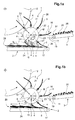
- Fig. 1a,b
- zwei Momentaufnahmen einer erfindungsgemässen Vorrichtung zur Bildung einer Doppelschuppenformation durch Freigabe eines ersten und eines zweiten Druckereiprodukts an einer ersten bzw. zweiten Übergabestelle;
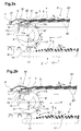
- Fig. 2a,b
- eine erfindungsgemässe Vorrichtung in zwei Momentaufnahmen zur Bildung einer Doppelschuppenformation durch Freigabe von ersten und zweiten Druckereiprodukten an einer gemeinsamen Übergabestelle;
- Fig. 3a
- die Vorrichtung aus Fig. 1a, b zur Bildung einer Rückwärts-Einzelschuppenformation;
- Fig. 3b
- die Vorrichtung aus Fig. 1a, b zur Bildung einer Vorwärts-Einzelschuppenformation;
- Fig. 4a
- die Vorrichtung aus Fig. 2a, b zur Bildung einer Rückwärts-Einzelschuppenformation;
- Fig. 4b
- die Vorrichtung aus Fig. 2a, b zur Bildung einer Vorwärts-Einzelschuppenformation.
- Fig. 1a, b
- two snapshots of an inventive device for forming a double scale formation by releasing a first and a second printed product at a first and a second transfer point;
- 2a, b
- a device according to the invention in two snapshots to form a double scale formation by releasing first and second printed products at a common transfer point;
- Fig. 3a
- 1a, b for the formation of a backward single-scale formation;
- Fig. 3b
- 1a, b to form a forward single-scale formation;
- Fig. 4a
- the device of Figures 2a, b to form a reverse single scale formation;
- Fig. 4b
- the device of Fig. 2a, b to form a forward single-scale formation.
Fig. 1a, b zeigen eine erfindungsgemässe Vorrichtung zur
Bildung einer Doppelschuppenformation in zwei Momentaufnahmen,
und zwar beim gleichzeitigen Ablegen eines
ersten und eines zweiten Druckereiprodukts 4 bzw. 5 (Fig.
1a), sowie eine halbe Periode T später (Fig. 1b), wobei T
die Zeit zwischen dem Ablegen zweier erster bzw. zweier
zweiter Druckereiprodukte 4, 5 angibt.1a, b show an inventive device for
Formation of a double scale formation in two snapshots,
and that at the same time dropping one
first and second printed
Die erfindungsgemässe Vorrichtung umfasst einen Zwischenförderer
1 mit einer Mehrzahl von auf einer rotierenden
Trommel 21 entlang ihres Umfangs angeordneten Greifern 6,
7. Die Greifer 6, 7 werden durch ortsfest im Raum angeordnete
Auslöseorgane 8, 9, 10, 16 geöffnet bzw. geschlossen,
wenn der Greifer beim Drehen der Trommel 21 an dem
entsprechenden Auslöseorgan vorbeiläuft. Die Auslöseorgane
sind beispielsweise geeignet ausgebildete Kulissen. Mit
einem an einer Aufnahmestelle 22 angeordneten ersten
Auslöseorgan 10 werden vorüberziehende Greifer 7, 6
geschlossen und ergreifen so aus einer Bearbeitungstrommel
12 kommende Druckereiprodukte 4, 5. Das erste Auslöseorgan
10 kann immer aktiv sein, um jeden an der Aufnahmestelle
22 vorbei bewegten Greifer 6, 7 zu schliessen. Die
Druckereiprodukte 4, 5 werden nun mittels der Greifer 6, 7
in Umfangrichtung entlang einer durch die Form der Trommel
21 vorgegebenen etwa kreisförmigen Bewegungsbahn U zu
einem Übergabebereich 15 im unteren Teil der Trommel 21
gefördert. Die Ausrichtung der Druckereiprodukte im Raum
kann durch Verschwenken der Greifer geändert werden, z.B.
auch mittels geeigneter Kulissen. Im Übergabebereich 15
unterhalb der Trommel 21 befindet sich ein erster
Wegförderer 2 in Form eines Bandförderers mit einem
Förderband 17. Im Übergabebereich 15 werden die vom
Zwischenförderer 1 geförderten ersten und zweiten
Druckereiprodukte 4 bzw. 5 abgelegt. Dabei liegt jeweils
ein zweites Druckereiprodukt 5 deckungsgleich auf einem
ersten 4 und bildet einen Stapel 24. Benachbarte Stapel 24
überlappen einander nur teilweise, so dass eine
Doppelschuppenformation 25 gebildet wird. Zum Ablegen
jeweils eines ersten Druckereiprodukts 4 auf das Förderband
bzw. teilweise auf den vorhergehenden Stapel 24 ist
ein erstes Abgabe-Auslöseorgan 8 vorhanden, der vorüberziehende
Greifer 6, die erste Druckereiprodukte 4
enthalten ("erste" Greifer) an einer ersten Übergabestelle
13 durch Öffnen frei gibt. Die erste Übergabestelle 13
befindet sich am tiefsten Punkt der Umlaufbahn U. Das
erste Abgabe-Auslöseorgan 8 ist so gesteuert, dass es
lediglich jeden zweiten vorüberziehenden Greifer 6, 7
öffnet, d.h. alle ersten Greifer 6 öffnet und alle zweiten
Greifer 7 geschlossen lässt. Dies kann durch
beispielsweise pneumatisch oder elektrisch gesteuerte
Bewegung der entsprechenden Öffnungskulisse in die bzw.
aus der Bewegungsbahn realisiert werden. Damit werden an
der ersten Übergabestelle 13 nur erste Druckereiprodukte 4
abgelegt. Alle zweiten Druckereiprodukte 5 werden
weitergezogen bis zu einer zweiten Übergabestelle 14, an
der ein zweites Abgabe-Auslöseorgan 9 angeordnet ist.
Dieses ist so eingestellt, dass es zumindest alle zweiten
Greifer 7 öffnet, so dass darin enthaltene zweite
Druckereiprodukte 5 an der zweiten Übergabestelle 14
abgelegt werden. Das zweite Abgabe-Auslöseorgan 9 kann
auch dauerhaft aktiv sein, wenn lediglich Stapel 24 aus
zwei Druckereiprodukten gebildet werden sollen. Das erste
Abgabe-Auslöseorgan 8 wird getaktet angesteuert, so dass
es jeweils nur jeden zweiten vorüberziehenden Greifer
öffnet. Es können aber auch die Abgabe-Auslöseorgane 8, 9
gleichzeitig angesteuert werden, um so Druckereiprodukte
4, 5 gleichzeitig freizugeben. Die nächste Freigabe
erfolgt dann zwei Takte später.The device according to the invention comprises an
Die Fördergeschwindigkeit v1, mit der die Greifer 6, 7 des
Zwischenförderers 1 umlaufen, die Fördergeschwindigkeit v2
des Förderbandes 17 des Wegförderers 2 sowie der Abstand
der ersten und zweiten Übergabestelle 13, 14 sind so aufeinander
abgestimmt, dass jeweils ein zweites Druckereiprodukt
5 möglichst genau auf ein erstes, bereits abgelegtes
Druckereiprodukt gelegt wird. Besonders einfach ist
es, wenn sich das Förderband 17 mit der halben Fördergeschwindigkeit
des Zwischenförderers bewegt. Die
Übergabestellen 13, 14 haben dabei vorzugsweise einen
Abstand D, der ungefähr dem Förderabstand d entspricht.The conveying speed v 1 at which the
Die in den Fig. 1a, 1b gezeigte Vorrichtung weist einen
zweiten Wegförderer 3 zur Bildung einer Rückwärts-Schuppenformation
auf, bei der das freie Ende 26 eines
Druckereiprodukts in Förderrichtung des zweiten Wegförderers
3 und das von den Greifern 6, 7 ergriffene Ende 27
entgegengestellt gerichtet ist. Der zweite Wegförderer 3
befindet sich in der Ebene der Umlaufbahn U des
Zwischenförderers 1 seitlich vom Zwischenförderer 1. Er
ist aus der dargestellten Position in eine Lage
verfahrbar, in der in einem weiteren Übergabebereich 16 an
einer dritten Übergabestelle 23 Druckereiprodukte 4, 5 auf
das Förderband 20 des Wegförderers 3 aufgelegt werden
können. Zum Öffnen von Greifern 6, 7 an dieser dritten
Übergabestelle 23 weist der Zwischenförderer 1 ein drittes
Abgabe-Auslöseorgan 18 auf, das in mittlerer Höhe des
Rades 21 angeordnet ist. Sollen Druckereiprodukte 4, 5 an
den zweiten Wegförderer 3 übergeben werden, so ist das
dritte Abgabe-Auslöseorgan 18 ständig aktiviert. Zur
Bildung einer Doppelschuppenformation werden die zweiten
Druckereiprodukte 5 mittels eines gestrichelt
dargestellten Zusatzförderers 11 auf die bereits
abgelegten ersten Druckereiprodukte 4 deckungsgleich
aufgeschoben. Dazu weist der Zusatzförderer 11 wenigstens
einen mit der doppelten Fördergeschwindigkeit wie der
Wegförderer 3 umlaufenden Aufschiebenocken 19 auf, der
jedes zweite ankommende Druckereiprodukt mitnimmt und auf
das vorhergehende erste Produkt aufschiebt. Ein solcher
Wegförderer wird in den Fig. 2a, b detaillierter gezeigt
und beschrieben. Der Wegförderer 3 und das dritte Abgabe-Auslöseorgan
18 können auch im oberen Bereich der Trommel
21 angeordnet sein, wobei das Förderband 20, wie in den
Fig. 2a, b dargestellt, tangential zur Bewegungsbahn der
Greifer 6, 7 verläuft. Alternativ kann ein Wegförderer mit
einem Zusatzförderer 11 auch im unteren Bereich, d.h.
unterhalb des Zwischenförderers 1 angeordnet sein.
Beispielsweise kann der Wegförderer 2 mit einem
Zusatzförderer ausgerüstet werden, der in gleichen
zeitlichen Abständen abgelegte erste und zweite
Druckereiprodukte jeweils zu Paaren aufeinander schiebt.
In diesem Fall kann auf ein zweites Abgabe-Auslöseorgan 9
verzichtet werden.The device shown in FIGS. 1a, 1b has one
Soll auf dem zweiten Wegförderer 3 nur eine Einfach-Schuppenformation
erzeugt werden, so kann auf den
Zusatzförderer 11 ganz verzichtet werden. Dies ist
beispielsweise dann der Fall, wenn die Vorrichtung nur zum
Umschalten zwischen verschiedenen Wegförderrichtungen bzw.
Wegförderpfaden oder zum Umschalten von Vorwärts- auf
Rückwärts-Schuppenformation dient.Should only a single scale formation on the
Fig. 2a, b zeigen eine weitere erfindungsgemässe Vorrichtung
mit einem Zwischenförderer 1', einem ersten Wegförderer
2' (gestrichelt dargestellt) und einem weiteren
Wegförderer 3'. Die Greifer 6', 7' laufen entlang einer
teilweise kreisförmigen Umlaufbahn U'. Im oberen Bereich
des Zwischenförderers 1' werden sämtliche Greifer 6', 7'
von einem Abgabe-Auslöseorgan 18' beim Vorbeilaufen
geöffnet. Die Druckereiprodukte 4, 5 werden auf ein im
Übergabebereich 16' tangential zur Umlaufbahn verlaufendes
Förderband 20' des Wegförderers 3' gelegt. Jedes zweite
Druckereiprodukt 5 wird mit einem Zusatzförderer 11' auf
das davor abgelegte erste Druckereiprodukt 4 aufgeschoben.
Der Zusatzförderer 11' weist dazu einen umlaufenden
Aufschiebenocken 19' auf, der in die Ebene des Förderbandes
20' hineinragt und sich mit der doppelten Geschwindigkeit
wie das Förderband 20' bewegt. Beispielsweise ist
der Zusatzförderer 11' seitlich vom Förderband 20' angeordnet.
Der Aufschiebenocken 19' ist an einem Förderorgan,
beispielsweise einem Band 11a befestigt, das um zwei
Walzen 11b, 11c läuft. Mit dem im oberen Teil der Fig.
2a, 2b gezeigten Wegförderer 3' wird eine Rückwärts-Doppelschuppenformation
25' gebildet, bei der die
ergriffenen Enden 27 der Druckereiprodukte entgegen der
Bewegungsrichtung des Wegförderers zeigen. Die
Fördergeschwindigkeit v2 des Wegförderers 3' beträgt etwa
die Hälfte der Fördergeschwindigkeit v1 des Zwischenförderers
1' im Übergabebereich 16'. Die Geschwindigkeit
des Aufschiebenockens 19' entspricht der Fördergeschwindigkeit
v1.2a, b show another device according to the invention with an intermediate conveyor 1 ', a
Im unteren Teil der Fig. 2a, 2b ist alternativ oder
zusätzlich zum Wegförderer 3' ein weiterer Wegförderer 2'
vorgesehen, der strichpunktiert dargestellt ist. Zum
Öffnen der ersten und zweiten Greifer 6', 7' an einer
ersten bzw. zweiten Übergabestelle 13', 14' sind erste
bzw. zweite Abgabe-Auslöseorgane 8', 9' voneinander beabstandet
angeordnet. Das zweite Abgabe-Auslöseorgan 9' wird
so angesteuert, dass es lediglich zweite Greifer 7', die
die zweite Übergabestelle 14' passieren, öffnet. Das erste
Abgabe-Auslöseorgan 8', das in Umdrehungsrichtung vor dem
zweiten Abgabe-Auslöseorgan 9' angeordnet ist, öffnet
vorzugsweise alle Greifer und führt daher zur Abgabe von
ersten Druckereiprodukten 4 an der ersten Übergabestelle
13'. Das Förderband 17' des Wegförderers 2' transportiert
entgegen der Förderrichtung des Zwischenförderers. Damit
wird ein an der zweiten Übergabestelle 14' freigegebenes
zweites Druckereiprodukt 5 auf das bereits abgelegte erste
Druckereiprodukt 4 aufgelegt. Die Fördergeschwindigkeiten
v1, v2' und der Abstand D der Abgabe-Auslöseorgane 8', 9'
sind dabei so aneinander angepasst, dass jeweils zwei
Produkte möglichst genau aufeinander aufgelegt werden.
Beispielsweise ist die Fördergeschwindigkeit des Wegförderers
v2 halb so gross wie die Fördergeschwindigkeit v1
des Zwischenförderers 1', und der Abstand zwischen erster
und zweiter Übergabestelle 13', 14' beträgt d/2.In the lower part of FIGS. 2a, 2b, as an alternative or in addition to the conveyor 3 ', a
Statt dem nach rechts entgegen der Förderrichtung des
Zwischenförderers wegfördernden Wegförderer 2' kann auch
ein in dieser Richtung wegfördernder Wegförderer verwendet
werden, wie er im unteren Teil der Fig. 1a, b gezeigt ist.
Die ersten und zweiten Auslöseorgan sind dann entsprechend
anzuordnen, so dass erste und zweite Druckereiprodukte
direkt aufeinander zu liegen kommen.Instead to the right against the conveying direction of the
Intermediate conveyor away
Soll mit dem unteren Wegförderer 2' nur eine
Einfachschuppenformation erzeugt werden, kann auf eines
der beiden Auslöseorgane 8', 9' verzichtet werden.Should only one with the
Die in den Fig. 1a, b, 2a, b nur schematisch gezeigten Auslöseorgane sind beispielsweise Öffnungskulissen, die in die Bewegungsbahn der Greifer einbringbar sind und mit ensprechenden Elementen der Greifer zusammenwirken, um die Greifer zu öffenen oder zu schliessen. Soll aus einer kontinuierlichen Folge von Druckereiprodukten nur jedes zweite abgegeben werden, wird die das Auslöseorgan bildene Öffnungskulisse im durch die Steuereinheit vorgegebenen Takt periodisch in die Bewegungsbahn eingebracht bzw. daraus entfernt.The only shown schematically in Figs. 1a, b, 2a, b Trigger organs are, for example, opening scenes that in the trajectory of the gripper can be introduced and with Corresponding elements of the grippers work together to achieve the Open or close the gripper. Should from one continuous sequence of printed products just every second are released, the one that forms the triggering element Opening setting in the control unit Periodically introduced into the movement path or removed from it.
In den Fig. 3a, b ist die Anordnung aus Fig. 1a, b beim
Umschalten zwischen einem ersten nach links wegführenden
Wegförderer 2 und einem zweiten nach rechts wegführenden
Wegförderer 3 gezeigt. Die dargestellten Elemente der
Vorrichtung entsprechen denen aus Fig. 1a, b und sind mit
denselben Bezugszeichen versehen. Der untere Wegförderer 2
wird bedient, wenn das dritte Abgabe-Auslöseorgan 18
deaktiviert und einer oder beide der weiteren Abgabe-Auslöseorgane
8, 9 aktiviert sind. Das erste und das
zweite Abgabe-Auslöseorgan 8, 9 werden aufeinander
abgestimmt aktiviert bzw. deaktiviert, wenn eine Doppelschuppe
gebildet werden soll, wie in Fig. 1a, b gezeigt.
Für die Bildung einer Einfachschuppe wie in Fig. 3a ist es
ausreichend, wenn eines der beiden Abgabe-Auslöseorgane 8,
9 ständig aktiv ist. Im vorliegenden Fall ist das erste
Abgabe-Auslöseorgan 8 inaktiv, so dass die Druckereiprodukte
erst bei der zweiten Übergabestelle 14 freigegeben
werden. Es kann leicht auf eine Doppelschuppenformation
umgeschaltet werden, indem das erste Abgabe-Auslöseorgan
8 in definierten Zeitabständen zugeschaltet
wird, um ein zweites Druckereiprodukt gleichzeitig mit
einem ersten Druckereiprodukt in der zweiten Übergabestelle
14 freizugeben. Der zweite Wegförderer 3 befindet
sich in Fig. 3a in einer Ruheposition, in der er die
Bewegung der Druckereiprodukte 4, 5 im Zwischenförderer 1
nicht behindert.3a, b is the arrangement of Fig. 1a, b at
Switch between a first one leading to the
In Fig. 3b ist der zweite Wegförderer 3 aktiv und an den
Zwischenförderer 1 herangefahren. Mittels des ständig
aktiven dritten Abgabe-Auslöseorgans 18 wird jeder Greifer
6, 7, der den zugeordneten Übergabebereich 23 passiert
geöffnet und legt ein Druckereiprodukt 4, 5 auf dem
Wegförderer 3 ab. Eine Einzelschuppe wird gebildet, indem
der Zusatzförderer 11 inaktiv ist, wie hier dargestellt.
Soll auf eine Doppelschuppenformation umgeschaltet werden,
wird der Zusatzförderer 11 aktiviert und schiebt somit
jeweils zwei Druckereiprodukte 4, 5 aufeinander. Soll
grundsätzlich keine Doppelschuppe gebildet werden, kann
auf den Zwischenförderer auch verzichtet werden.In Fig. 3b, the
Die Fig. 4a, b zeigen das Umschalten zwischen dem
Wegfördern mit einem ersten Wegförderer 2' und einem
zweiten Wegförderer 3' nach links bzw. rechts mit der
Anordnung aus Fig. 2a, b. Durch Aktivieren des dritten
Abgabe-Auslöseorgans 18' werden die Druckereiprodukte an
einer dritten Übergabestelle 23' auf das Förderband des
Wegförderers 3' gelegt, siehe Fig. 4a. Eine Doppelschuppenformation
wird gebildet, indem der Zusatzförderer
11' aktiviert wird. Hier ist eine Einzelschuppenformation
bei inaktivem Zusatzförderer 11' dargestellt. Sollen nur
Einzelschuppenformationen gebildet werden, kann auf den
Zusatzförderer 11' auch verzichtet werden. Zum Wegfördern
über den unteren Wegförderer 2' wird das Abgabe-Auslöseorgan
18' deaktiviert und eines der Abgabe-Auslöseorgan
8', 9' bzw. beide aktiviert. Damit werden
Druckereiprodukte an der ersten und/oder zweiten Übergabestelle
13', 14' auf das Förderband des Wegförderers 2'
gelegt. Im in Fig. 4b dargestellten Fall ist nur das
zweite Abgabe-Auslöseorgan 9' aktiv, so dass eine
Einzelschuppenformation gebildet wird.4a, b show the switching between the
Conveying away with a
Claims (22)
dadurch gekennzeichnet, dass der Wegförderer im Übergabebereich in horizontaler Richtung im unteren Bereich des Zwischenförderers von diesem beabstandet verläuft, so dass die Druckereiprodukte von oben abgelegt werden können, wobei die Förderrichtungen des Wegförderers und des Zwischenförderers im Übergabebereich gleich gerichtet oder einander entgegengesetzt sind.Device according to one of claims 8 to 10,
characterized in that the removal conveyor in the transfer area extends horizontally in the lower area of the intermediate conveyor, so that the printed products can be deposited from above, the conveying directions of the removal conveyor and of the intermediate conveyor being oriented in the same direction or opposite to each other.
dadurch gekennzeichnet, dass ein weiterer Wegförderer in Form eines Bandförderers mit einem in horizontaler Richtung verlaufenden Förderband vorhanden ist, der in einem weiteren Übergabebereich Druckereiprodukte zu übernehmen imstande ist.Device according to one of claims 8 to 13,
characterized in that there is a further conveyor in the form of a belt conveyor with a conveyor belt running in the horizontal direction, which is able to take over printed products in a further transfer area.
dadurch gekennzeichnet, dass die Umlaufbahn U des Zwischenförderers vorzugsweise wenigstens im Übergabebereich kreisbogenförmig ist.Device according to one of claims 8 to 16,
characterized in that the orbit U of the intermediate conveyor is preferably in the form of a circular arc at least in the transfer area.
Applications Claiming Priority (2)
| Application Number | Priority Date | Filing Date | Title |
|---|---|---|---|
| CH19312000 | 2000-10-02 | ||
| CH19312000 | 2000-10-02 |
Publications (2)
| Publication Number | Publication Date |
|---|---|
| EP1193201A1 true EP1193201A1 (en) | 2002-04-03 |
| EP1193201B1 EP1193201B1 (en) | 2004-01-28 |
Family
ID=4566824
Family Applications (1)
| Application Number | Title | Priority Date | Filing Date |
|---|---|---|---|
| EP01120926A Expired - Lifetime EP1193201B1 (en) | 2000-10-02 | 2001-08-31 | Method and device for forming a double shingled formation of printed products |
Country Status (5)
| Country | Link |
|---|---|
| US (1) | US6619651B2 (en) |
| EP (1) | EP1193201B1 (en) |
| AT (1) | ATE258533T1 (en) |
| DE (1) | DE50101385D1 (en) |
| DK (1) | DK1193201T3 (en) |
Cited By (1)
| Publication number | Priority date | Publication date | Assignee | Title |
|---|---|---|---|---|
| EP1364899A1 (en) * | 2002-05-22 | 2003-11-26 | Ferag AG | Method for transporting flat and flexible products, and device for carrying out the method |
Families Citing this family (11)
| Publication number | Priority date | Publication date | Assignee | Title |
|---|---|---|---|---|
| AU2001268888B2 (en) * | 2000-07-24 | 2006-09-07 | Ferag Ag | Method and device for the stacking of flat objects |
| AU7953701A (en) * | 2000-08-18 | 2002-02-25 | Ferag Ag | Method and arrangement for the production of crossed stacks |
| CA2458384C (en) * | 2001-10-05 | 2010-06-22 | Ferag Ag | Method of processing sheet-like products, and apparatus for implementing the method |
| ATE337996T1 (en) * | 2001-12-21 | 2006-09-15 | Ferag Ag | METHOD AND DEVICE FOR FEEDING FLAT PRODUCTS |
| AUPS061402A0 (en) * | 2002-02-19 | 2002-03-14 | Tna Australia Pty Limited | A device to aid packaging items |
| DK1340704T3 (en) * | 2002-03-01 | 2005-10-24 | Ferag Ag | Method and apparatus for transforming a stream of held conveyed flat objects into a flag stream with selectable arrangement of the articles |
| FR2890333B1 (en) * | 2005-09-07 | 2009-01-23 | Mag Systemes Soc Par Actions S | AUTOMATIC ENVELOPE FEEDING DEVICE FOR A WORKSHOP FOR PLACING DOCUMENTS |
| EP1834913A1 (en) * | 2006-03-17 | 2007-09-19 | Ferag AG | Device for picking up and conveying of flat products |
| US7694949B2 (en) * | 2006-09-18 | 2010-04-13 | Goss International Americas, Inc | Custodial lapped stream mechanism |
| EP2100839B1 (en) * | 2008-03-14 | 2012-12-19 | Müller Martini Holding AG | Transport device for the acquisition and transfer of printed items |
| CH701214A1 (en) * | 2009-06-03 | 2010-12-15 | Ferag Ag | Apparatus and method for processing printed products. |
Citations (6)
| Publication number | Priority date | Publication date | Assignee | Title |
|---|---|---|---|---|
| FR2420499A1 (en) * | 1978-03-23 | 1979-10-19 | Ferag Ag | DEVICE FOR FORMING A CONTINUOUS DERIVATIVE LINE, FROM A CONTINUOUS MAIN LINE OF FLAT ARTICLES, IN PARTICULAR OF PRINTS |
| US4509703A (en) * | 1982-05-05 | 1985-04-09 | Grapha-Holding Ag | Method and apparatus for transporting and storing partially overlapping sheets |
| US4696464A (en) * | 1985-01-29 | 1987-09-29 | Gaemmerler Hagen | Method of and an apparatus for uniting at least two streams of shingled laid out products, particularly folded paper products |
| US4770407A (en) * | 1987-01-29 | 1988-09-13 | Craftsman Printing Company | Apparatus and method for merging two signature streams |
| US5028045A (en) * | 1989-07-10 | 1991-07-02 | Ferag Ag | Apparatus for taking over printing products from a rotatably driven paddle wheel of a printing machine |
| US5295679A (en) * | 1991-06-27 | 1994-03-22 | Ferag Ag | Method and apparatus for conveying away flat products supplied in scale flow, particularly printed products |
Family Cites Families (11)
| Publication number | Priority date | Publication date | Assignee | Title |
|---|---|---|---|---|
| DE3108681A1 (en) * | 1981-03-07 | 1982-09-30 | M.A.N.- Roland Druckmaschinen AG, 6050 Offenbach | "DEVICE FOR REMOVING PRINTED COPIES FROM THE BUCKET WHEELS OF A FOLDING APPARATUS" |
| DE3404459A1 (en) * | 1984-02-08 | 1985-08-14 | Frankenthal Ag Albert | METHOD AND DEVICE FOR DISPLAYING ARC-SHAPED PRODUCTS IN THE FORM OF A SHED FLOW |
| DE3545271A1 (en) * | 1985-12-20 | 1987-07-02 | Roland Man Druckmasch | METHOD AND DEVICE FOR BRAKING AND LAYING OUT OF SHEETS OR SHEET PACKS PRINTED IN A PRINTING MACHINE |
| DE59002539D1 (en) | 1989-07-18 | 1993-10-07 | Ferag Ag | Device for laying out printed products. |
| RU2053184C1 (en) * | 1990-08-06 | 1996-01-27 | Радуцкий Григорий Аврамович | Device for bringing newspaper products out of folder of web-rotary machine |
| WO1994019268A1 (en) * | 1993-02-26 | 1994-09-01 | Gutov Sergei K | Pick-up device for taking newspapers from the folder of a rotary printing-press |
| DK0677470T3 (en) * | 1994-04-15 | 1998-10-07 | Ferag Ag | Method of storing surface-shaped products |
| DK0686463T3 (en) | 1994-06-08 | 2000-01-03 | Ferag Ag | Apparatus for pruning printing products, e.g. newspapers, magazines and brochures, on at least two margins |
| SE502958C2 (en) * | 1994-08-19 | 1996-02-26 | Sten Wallsten Ind Ab | Device for delivering selected specimens of objects from a conveyor belt |
| DE59608549D1 (en) | 1995-07-11 | 2002-02-14 | Ferag Ag | Device for trimming folded printed matter such as newspapers, magazines, brochures and the like |
| US5927712A (en) * | 1996-11-12 | 1999-07-27 | Heidelberg Harris | Sample signature delivery having alternate transport path away from deceleration device |
-
2001
- 2001-08-31 DE DE50101385T patent/DE50101385D1/en not_active Expired - Lifetime
- 2001-08-31 DK DK01120926T patent/DK1193201T3/en active
- 2001-08-31 AT AT01120926T patent/ATE258533T1/en not_active IP Right Cessation
- 2001-08-31 EP EP01120926A patent/EP1193201B1/en not_active Expired - Lifetime
- 2001-09-26 US US09/968,413 patent/US6619651B2/en not_active Expired - Fee Related
Patent Citations (6)
| Publication number | Priority date | Publication date | Assignee | Title |
|---|---|---|---|---|
| FR2420499A1 (en) * | 1978-03-23 | 1979-10-19 | Ferag Ag | DEVICE FOR FORMING A CONTINUOUS DERIVATIVE LINE, FROM A CONTINUOUS MAIN LINE OF FLAT ARTICLES, IN PARTICULAR OF PRINTS |
| US4509703A (en) * | 1982-05-05 | 1985-04-09 | Grapha-Holding Ag | Method and apparatus for transporting and storing partially overlapping sheets |
| US4696464A (en) * | 1985-01-29 | 1987-09-29 | Gaemmerler Hagen | Method of and an apparatus for uniting at least two streams of shingled laid out products, particularly folded paper products |
| US4770407A (en) * | 1987-01-29 | 1988-09-13 | Craftsman Printing Company | Apparatus and method for merging two signature streams |
| US5028045A (en) * | 1989-07-10 | 1991-07-02 | Ferag Ag | Apparatus for taking over printing products from a rotatably driven paddle wheel of a printing machine |
| US5295679A (en) * | 1991-06-27 | 1994-03-22 | Ferag Ag | Method and apparatus for conveying away flat products supplied in scale flow, particularly printed products |
Cited By (1)
| Publication number | Priority date | Publication date | Assignee | Title |
|---|---|---|---|---|
| EP1364899A1 (en) * | 2002-05-22 | 2003-11-26 | Ferag AG | Method for transporting flat and flexible products, and device for carrying out the method |
Also Published As
| Publication number | Publication date |
|---|---|
| DE50101385D1 (en) | 2004-03-04 |
| ATE258533T1 (en) | 2004-02-15 |
| DK1193201T3 (en) | 2004-03-08 |
| EP1193201B1 (en) | 2004-01-28 |
| US20020038752A1 (en) | 2002-04-04 |
| US6619651B2 (en) | 2003-09-16 |
Similar Documents
| Publication | Publication Date | Title |
|---|---|---|
| EP0330868B1 (en) | Process and device for conveying away printed products fed in a shingled formation | |
| CH688091A5 (en) | Flexible Foerdersystem. | |
| EP0755783A2 (en) | Printing machine with rectilinear substrate guiding and turning devices | |
| EP1193201B1 (en) | Method and device for forming a double shingled formation of printed products | |
| DE3135930C2 (en) | ||
| EP1321410B1 (en) | Method and device for transporting flat products | |
| DE3145491A1 (en) | "DEVICE FOR LAYING UP SINGLE AREA PRODUCTS, IN PARTICULAR PRINTED PRODUCTS" | |
| EP0368009A1 (en) | Method and device for advancing printed articles | |
| EP0754642B1 (en) | Method and device for delivering sheet-like products | |
| EP0854105B1 (en) | Method and device for traiting flat printed products, such as newspapers and magazines, and parts thereof | |
| EP1057762B1 (en) | Method and device for transporting objects arriving in overlapping formation | |
| EP1124747B1 (en) | Method and device for delivering printed products | |
| DE4116969A1 (en) | DEVICE FOR PROMOTING PAPER SHEET STACKS | |
| EP0210494A1 (en) | Collecting device for folded printed sheets | |
| EP0647582A1 (en) | Device for opening and further conveying printed products | |
| EP0765247A1 (en) | Method and device for processing printed products | |
| DE2832660B2 (en) | Device for group-wise division of workpieces conveyed on top of each other in shingled form | |
| EP1509398B1 (en) | Delivery device for a sheet processing machine | |
| CH627997A5 (en) | Device for forming a continuous branch stream from a main stream of continuously occurring flat products, in particular printed products | |
| DE2717554A1 (en) | Sheet feed system for printer - with top sheet offset by constant amount from others and aligned by lateral traction (SW 14.11.77) | |
| EP1227052B1 (en) | Method and device for changing the gripping position of flat objects, conveyed by grippers | |
| EP1669312A1 (en) | Device for the further one-line transport of flat objects coming from a feeding device and being stacked on support | |
| EP0806391A1 (en) | Device for feeding printed articles to a further work station | |
| EP1657199B1 (en) | Apparatus for handling of flat products, in particular print products | |
| EP1231173B1 (en) | Device for composing a printed product of superposed printed sheets in a certain order |
Legal Events
| Date | Code | Title | Description |
|---|---|---|---|
| PUAI | Public reference made under article 153(3) epc to a published international application that has entered the european phase |
Free format text: ORIGINAL CODE: 0009012 |
|
| AK | Designated contracting states |
Kind code of ref document: A1 Designated state(s): AT BE CH CY DE DK ES FI FR GB GR IE IT LI LU MC NL PT SE TR |
|
| AX | Request for extension of the european patent |
Free format text: AL;LT;LV;MK;RO;SI |
|
| 17P | Request for examination filed |
Effective date: 20020311 |
|
| 17Q | First examination report despatched |
Effective date: 20021106 |
|
| AKX | Designation fees paid |
Free format text: AT BE CH CY DE DK ES FI FR GB GR IE IT LI LU MC NL PT SE TR |
|
| GRAH | Despatch of communication of intention to grant a patent |
Free format text: ORIGINAL CODE: EPIDOS IGRA |
|
| GRAS | Grant fee paid |
Free format text: ORIGINAL CODE: EPIDOSNIGR3 |
|
| GRAA | (expected) grant |
Free format text: ORIGINAL CODE: 0009210 |
|
| AK | Designated contracting states |
Kind code of ref document: B1 Designated state(s): AT BE CH CY DE DK ES FI FR GB GR IE IT LI LU MC NL PT SE TR |
|
| PG25 | Lapsed in a contracting state [announced via postgrant information from national office to epo] |
Ref country code: FI Free format text: LAPSE BECAUSE OF FAILURE TO SUBMIT A TRANSLATION OF THE DESCRIPTION OR TO PAY THE FEE WITHIN THE PRESCRIBED TIME-LIMIT Effective date: 20040128 Ref country code: TR Free format text: LAPSE BECAUSE OF FAILURE TO SUBMIT A TRANSLATION OF THE DESCRIPTION OR TO PAY THE FEE WITHIN THE PRESCRIBED TIME-LIMIT Effective date: 20040128 Ref country code: IE Free format text: LAPSE BECAUSE OF FAILURE TO SUBMIT A TRANSLATION OF THE DESCRIPTION OR TO PAY THE FEE WITHIN THE PRESCRIBED TIME-LIMIT Effective date: 20040128 Ref country code: CY Free format text: LAPSE BECAUSE OF FAILURE TO SUBMIT A TRANSLATION OF THE DESCRIPTION OR TO PAY THE FEE WITHIN THE PRESCRIBED TIME-LIMIT Effective date: 20040128 |
|
| REG | Reference to a national code |
Ref country code: GB Ref legal event code: FG4D Free format text: NOT ENGLISH |
|
| REG | Reference to a national code |
Ref country code: CH Ref legal event code: EP |
|
| REG | Reference to a national code |
Ref country code: CH Ref legal event code: NV Representative=s name: PATENTANWAELTE SCHAAD, BALASS, MENZL & PARTNER AG |
|
| REG | Reference to a national code |
Ref country code: SE Ref legal event code: TRGR |
|
| GBT | Gb: translation of ep patent filed (gb section 77(6)(a)/1977) |
Effective date: 20040128 |
|
| REG | Reference to a national code |
Ref country code: IE Ref legal event code: FG4D Free format text: GERMAN |
|
| REF | Corresponds to: |
Ref document number: 50101385 Country of ref document: DE Date of ref document: 20040304 Kind code of ref document: P |
|
| REG | Reference to a national code |
Ref country code: DK Ref legal event code: T3 |
|
| PG25 | Lapsed in a contracting state [announced via postgrant information from national office to epo] |
Ref country code: GR Free format text: LAPSE BECAUSE OF FAILURE TO SUBMIT A TRANSLATION OF THE DESCRIPTION OR TO PAY THE FEE WITHIN THE PRESCRIBED TIME-LIMIT Effective date: 20040428 |
|
| PG25 | Lapsed in a contracting state [announced via postgrant information from national office to epo] |
Ref country code: ES Free format text: LAPSE BECAUSE OF FAILURE TO SUBMIT A TRANSLATION OF THE DESCRIPTION OR TO PAY THE FEE WITHIN THE PRESCRIBED TIME-LIMIT Effective date: 20040509 |
|
| REG | Reference to a national code |
Ref country code: IE Ref legal event code: FD4D |
|
| PG25 | Lapsed in a contracting state [announced via postgrant information from national office to epo] |
Ref country code: MC Free format text: LAPSE BECAUSE OF NON-PAYMENT OF DUE FEES Effective date: 20040831 Ref country code: LU Free format text: LAPSE BECAUSE OF NON-PAYMENT OF DUE FEES Effective date: 20040831 Ref country code: BE Free format text: LAPSE BECAUSE OF NON-PAYMENT OF DUE FEES Effective date: 20040831 Ref country code: AT Free format text: LAPSE BECAUSE OF NON-PAYMENT OF DUE FEES Effective date: 20040831 |
|
| ET | Fr: translation filed | ||
| PLBE | No opposition filed within time limit |
Free format text: ORIGINAL CODE: 0009261 |
|
| STAA | Information on the status of an ep patent application or granted ep patent |
Free format text: STATUS: NO OPPOSITION FILED WITHIN TIME LIMIT |
|
| 26N | No opposition filed |
Effective date: 20041029 |
|
| REG | Reference to a national code |
Ref country code: CH Ref legal event code: PFA Owner name: FERAG AG Free format text: FERAG AG#ZUERICHSTRASSE 74#8340 HINWIL (CH) -TRANSFER TO- FERAG AG#PATENTABTEILUNG Z. H. MARKUS FELIX ZUERICHSTRASSE 74#8340 HINWIL (CH) |
|
| BERE | Be: lapsed |
Owner name: *FERAG A.G. Effective date: 20040831 |
|
| PGFP | Annual fee paid to national office [announced via postgrant information from national office to epo] |
Ref country code: FR Payment date: 20050812 Year of fee payment: 5 Ref country code: NL Payment date: 20050812 Year of fee payment: 5 |
|
| PG25 | Lapsed in a contracting state [announced via postgrant information from national office to epo] |
Ref country code: NL Free format text: LAPSE BECAUSE OF NON-PAYMENT OF DUE FEES Effective date: 20070301 |
|
| NLV4 | Nl: lapsed or anulled due to non-payment of the annual fee |
Effective date: 20070301 |
|
| REG | Reference to a national code |
Ref country code: FR Ref legal event code: ST Effective date: 20070430 |
|
| BERE | Be: lapsed |
Owner name: *FERAG A.G. Effective date: 20040831 |
|
| PG25 | Lapsed in a contracting state [announced via postgrant information from national office to epo] |
Ref country code: PT Free format text: LAPSE BECAUSE OF NON-PAYMENT OF DUE FEES Effective date: 20040628 |
|
| PG25 | Lapsed in a contracting state [announced via postgrant information from national office to epo] |
Ref country code: FR Free format text: LAPSE BECAUSE OF NON-PAYMENT OF DUE FEES Effective date: 20060831 |
|
| PGFP | Annual fee paid to national office [announced via postgrant information from national office to epo] |
Ref country code: DK Payment date: 20110822 Year of fee payment: 11 |
|
| PGFP | Annual fee paid to national office [announced via postgrant information from national office to epo] |
Ref country code: GB Payment date: 20110819 Year of fee payment: 11 |
|
| PGFP | Annual fee paid to national office [announced via postgrant information from national office to epo] |
Ref country code: IT Payment date: 20110825 Year of fee payment: 11 |
|
| PGFP | Annual fee paid to national office [announced via postgrant information from national office to epo] |
Ref country code: SE Payment date: 20120821 Year of fee payment: 12 |
|
| GBPC | Gb: european patent ceased through non-payment of renewal fee |
Effective date: 20120831 |
|
| PG25 | Lapsed in a contracting state [announced via postgrant information from national office to epo] |
Ref country code: IT Free format text: LAPSE BECAUSE OF NON-PAYMENT OF DUE FEES Effective date: 20120831 |
|
| PG25 | Lapsed in a contracting state [announced via postgrant information from national office to epo] |
Ref country code: GB Free format text: LAPSE BECAUSE OF NON-PAYMENT OF DUE FEES Effective date: 20120831 |
|
| REG | Reference to a national code |
Ref country code: DK Ref legal event code: EBP Effective date: 20130831 |
|
| REG | Reference to a national code |
Ref country code: SE Ref legal event code: EUG |
|
| PG25 | Lapsed in a contracting state [announced via postgrant information from national office to epo] |
Ref country code: SE Free format text: LAPSE BECAUSE OF NON-PAYMENT OF DUE FEES Effective date: 20130901 |
|
| PG25 | Lapsed in a contracting state [announced via postgrant information from national office to epo] |
Ref country code: DK Free format text: LAPSE BECAUSE OF NON-PAYMENT OF DUE FEES Effective date: 20130831 |
|
| PGFP | Annual fee paid to national office [announced via postgrant information from national office to epo] |
Ref country code: DE Payment date: 20140821 Year of fee payment: 14 |
|
| PGFP | Annual fee paid to national office [announced via postgrant information from national office to epo] |
Ref country code: CH Payment date: 20141029 Year of fee payment: 14 |
|
| REG | Reference to a national code |
Ref country code: DE Ref legal event code: R119 Ref document number: 50101385 Country of ref document: DE |
|
| REG | Reference to a national code |
Ref country code: CH Ref legal event code: PL |
|
| PG25 | Lapsed in a contracting state [announced via postgrant information from national office to epo] |
Ref country code: CH Free format text: LAPSE BECAUSE OF NON-PAYMENT OF DUE FEES Effective date: 20150831 Ref country code: LI Free format text: LAPSE BECAUSE OF NON-PAYMENT OF DUE FEES Effective date: 20150831 |
|
| PG25 | Lapsed in a contracting state [announced via postgrant information from national office to epo] |
Ref country code: DE Free format text: LAPSE BECAUSE OF NON-PAYMENT OF DUE FEES Effective date: 20160301 |